
Service Manual


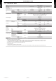

Table Of Contents
- SERVICE MANUAL
- 1. GENERAL INFORMATION
- 2. TECHNICAL DATA AND PARTS LIST
- 3. TROUBLESHOOTING
- 1. Error code
- 2. Troubleshooting with error code
- 2-1. E: 11. Serial communication error (Serial reverse transfer error) (Outdoor unit)
- 2-2. E: 11. Serial communication error (Serial forward transfer error) (Indoor unit)
- 2-3. E: 12. Wired remote controller communication error (Indoor unit)
- 2-4. E: 18. External communication error (Indoor unit)
- 2-5. E: 32. Indoor unit main PCB error (Indoor unit)
- 2-6. E: 35. MANUAL AUTO button error (Indoor unit)
- 2-7. E: 41. Room temperature sensor error (Indoor unit)
- 2-8. E: 42. Indoor unit heat exchanger sensor error (Indoor unit)
- 2-9. E: 51. Indoor unit fan motor error (Indoor unit)
- 2-10. E: 58. Intake grille error (Indoor unit)
- 2-11. E: 62. Outdoor unit main PCB error (Outdoor unit)
- 2-12. E: 63. Inverter error (Outdoor unit)
- 2-13. E: 64. PFC circuit error (Outdoor unit)
- 2-14. E: 71. Discharge thermistor error (Outdoor unit)
- 2-15. E: 73. Outdoor unit heat exchanger thermistor error (Outdoor unit)
- 2-16. E: 74. Outdoor temperature thermistor error (Outdoor unit)
- 2-17. E: 84. Current sensor error (Outdoor unit)
- 2-18. E: 94. Trip detection (Outdoor unit)
- 2-19. E: 95. Compressor motor control error (Outdoor unit)
- 2-20. E: 97. Outdoor unit fan motor error (Outdoor unit)
- 2-21. E: 99. 4-way valve error (Outdoor unit)
- 2-22. E: A1. Discharge temperature error (Outdoor unit)
- 3. Troubleshooting without error code
- 4. Troubleshooting with error code (For wireless LAN adapter)
- 4-1. E: 18. External communication error between indoor unit and WLAN adapter
- 4-2. Wireless LAN adapter error
- 4-3. Network communication error between wireless LAN router and WLAN adapter
- 4-4. E: 18. Communication error
- 4-5. E: 18. Wireless LAN adapter non-energized
- 4-6. Wireless LAN adapter Sleep mode (Indoor unit)
- 4-7. Mobile app setting method
- 5. Service parts information
- 6. Thermistor resistance values
- 4. CONTROL AND FUNCTIONS
- 1. Compressor frequency control
- 2. Auto changeover operation
- 3. Fan control
- 4. Louver control
- 5. Timer operation control
- 6. Defrost operation control
- 7. Various control
- 7-1. Auto restart
- 7-2. MANUAL AUTO operation
- 7-3. Forced cooling operation
- 7-4. 10 °C HEAT operation
- 7-5. ECONOMY operation
- 7-6. POWERFUL operation
- 7-7. Compressor preheating
- 7-8. Electronic expansion valve control
- 7-9. Prevention to restart for 3 minutes (3 minutes st)
- 7-10. 4-way valve control
- 7-11. Outdoor unit low noise operation
- 8. Various protections
- 5. FILED WORKING

1-2. Outdoor unit
Type Inverter heat pump
Model name AOUG09LZAH1 AOUG12LZAH1 AOUG15LZAH1
Power supply 208/230 V ~ 60 Hz
Available voltage range 187—253 V
Starting current A 3.3 4.7 5.2
Fan
Airflow rate
Cooling
CFM (m
3
/h)
1,089 (1,850) 1,171 (1,990) 1,218 (2,070)
Heating 1,089 (1,850) 1,089 (1,850) 1,348 (2,290)
Type × Q'ty Propeller fan × 1
Motor output W 49
Sound pressure level *1
Cooling
dB (A)
46 47 49
Heating 47 47 50
Heat exchanger type
Dimensions
(H × W × D)
in (mm)
Main1: 23-1/8 × 34-11/16 × 11/16 (588 × 881 × 18.19)
Main2: 23-1/8 ×33-1/2 × 11/16 (588 × 851 × 18.19)
Fin pitch FPI 20
Rows × Stages
Main1: 1 × 28
Main2: 1 × 28
Pipe type Copper
Fin type
Type (Material) Aluminum
Surface treatment PC fin
Compressor
Type DC rotary
Motor output W 900 1,030
Refrigerant
Type R410A
Charge
lb oz 2 lb 14 oz 2 lb 16 oz
g 1,300 1,350
Refrigerant oil
Type RB68
Amount
in
3
(cm
3
)
24.4 (400)
Enclosure
Material Steel sheet
Color
Beige
Approximate color of Munsell 10YR 7.5/1.0
Dimensions
(H × W × D)
Net
in (mm)
24-7/8 × 31-7/16 × 11-7/16 (632 × 799 × 290)
Gross 27-1/4 × 37 × 14-3/4 (692 × 940 × 375)
Weight
Net
lb (kg)
86 (39) 88 (40)
Gross 95 (43)
Connection pipe
Size
Liquid
in (mm)
Ø 1/4 (Ø 6.35)
Gas Ø 3/8 (Ø 9.52) Ø 1/2 (Ø 12.7)
Method Flare
Pre-charge length
ft (m)
49 (15)
Max. length 66 (20)
Max. height difference 49 (15)
Operation range
Cooling
°F (°C)
14 to 115 (-10 to 46)
Heating -15 to 75 (-26 to 24)
NOTES:
• Specifications are based on the following conditions:
– Cooling: Indoor temperature of 80 °FDB (26.67 °CDB) / 67 °FWB (19.44 °CWB), and outdoor temperature of 95 °FDB (35 °CDB) / 75 °FWB (23.9 °CWB).
– Heating: Indoor temperature of 70 °FDB (21.11 °CDB) / 59 °FWB (15 °CWB), and outdoor temperature of 47 °FDB (8.33 °CDB) / 43 °FWB (6.11 °CWB).
– Pipe length: 24 ft 6 in (7.5 m), Height difference: 0 ft (0 m). (Between outdoor unit and indoor unit.)
• Protective function might work when using it outside the operation range.
• *1: Sound pressure level
– Measured values in manufacturer’s anechoic chamber.
– Because of the surrounding sound environment, the sound levels measured in actual installation conditions might be higher than the specified values here.
1-2. Outdoor unit
- (01-3) - 1. Specifications
GENERAL
INFORMATION
GENERAL
INFORMATION