DESKPOWER 2000 Series User’s Manual Fujitsu endeavours to ensure that the information in this document is correct, but accepts no liability for any error or omission in the same. Any procedures described in this document for operating Fujitsu products should be read and understood by the operator before such products are used. To ensure that Fujitsu products function without risk to safety and health, such procedures should be strictly observed by the operator.
IMPORTANT SAFETY INSTRUCTIONS 1. Read these instructions carefully. Save these instructions for future reference. 2. Follow all warnings and instructions marked on the product. 3. Unplug this product from the wall outlet before cleaning. Do not use liquid cleaners or aerosol cleaners. Use a damp cloth for cleaning. 4. Do not use this product near water. 5. Do not place this product on an unstable cart, stand, or table. The product may fall, causing serious damage to the product. 6.
10. If an extension cord is used with this product, make sure that the total ampere rating of the equipment plugged into the extension cord does not exceed the extension cord ampere rating. Also, make sure that the total rating of all products plugged into the wall outlet does not exceed 15 amperes. 11. Never push objects of any kind into this product through cabinet slots as they may touch dangerous voltage points that could result in a fire or electric shock. Never spill liquid of any kind on the product.
Starting your PC for the first time iv She int _i-xv 4 19/1/00, 16:27
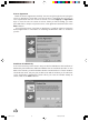
Starting your PC for the first time Booting the System When you turn on your PC for the first time, it will display a Fujitsu logo on the screen. If you do nothing, the system will read the hard drive for the operating system software, flash the system configuration information on the screen, and then Setup Wizard Screen will appear. You will then be stepped through the Conditions of Use process. You must complete this initial process before you will be able to use your PC.
License Agreement Read the license agreement carefully. You can scroll through the text using the mouse to activate the scroll bar or use the up arrow ↑ and down arrow ↓ keys to move up and down the text one line at a time or use the Page Up or Page Down keys to move the text one screen at a time. When you finish reading, you must point and click to accept or reject the terms of the agreement and then click on the Next > button.
Time Zone When your PC has completely identified all of the installed hardware, it will display a dialog box entering which time zone you wish to set the clock to. Windows® Messaging Once you have selected a time zone, you will see a screen announcing that Windows® messaging is being set up. Printer Setup When the messaging setup is complete, a dialog box will appear for selecting which printer is to be attached to your system. You do not have to select a printer, so click on the Cancel button.
B. Software Drivers and Application You will find a Composite CD packet in your accessories box. Please store the packet in a safe place in case there is a loss of data and it becomes necessary to reinstall your operating system and/or applications. The Composite CD will contain all the necessary drivers for re-loading. C. Learning About Your Operating System and Application Software Tutorials All operating systems and most application software have tutorials built-in.
About this manual ix She int _i-xv 9 19/1/00, 16:28
About this Manual Purpose This user’s guide aims to give you all the necessary information to enable you to operate the system properly. Manual Structure This user’s guide consists of two chapters. Chapter 1 System Board This chapter describes the system board and all its major components. It contains the system board layout, jumper settings, cache and memory configuration, and information on other internal devices.
Conventions The following are the conventions used in this manual: Text entered by user Screen messages a, e, s, etc. Represents text input by the user. Denotes actual messages that appear on the screen. Represents the actual keys that you have to press on the keyboard. NOTE Gives bits and pieces of additional information related to the current topic. WARNING Alerts you to any damage that might result from doing or not doing specific actions.
contents SYSTEM BOARD 1.1 MAINBOARD FEATURES ................................................................. 3 1.2. MAINBOARD LAYOUT ..................................................................... 6 1.3. QUICK REFERENCE FOR JUMPERS & CONNECTORS ......................... 7 1.4 CASE CONNECTOR: JFP1 ............................................................... 8 1.4.1 1.4.2 1.4.3 1.4.4 1.4.5 1.4.6 table of Chapter 1 1.5 CLEAR CMOS JUMPER: JBAT1/J26 ......................................
1.9 POWER SAVING SWITCH CONNECTOR: JGS1 ................................. 20 1.9.1 POWER SAVING LED CONNECTOR: JGL1 ............................ 21 1.10 Onboard Audio Enabled/Disabled Jumper: JP4 .............................. 22 1.11 MODEM WAKE UP CONNECTOR: JMDM1 ....................................... 23 1.12 MODEM-IN: J6 ............................................................................. 24 1.13 AUX LINE IN CONNECTOR: J5 ....................................................... 25 1.
2.7 INTEGRATED PERIPHERALS .......................................................... 40 2.8 POWER MANAGEMENT SETUP ...................................................... 44 RELOAD GLOBAL TIMER EVENTS .................................................. 47 2.9 PNP/PCI CONFIGURATION SETUP ................................................. 47 2.10 FREQUENCY/VOLTAGE CONTROL .................................................. 49 2.11 LOAD FAIL-SAFE/OPTIMIZED DEFAULTS .........................................
She_Chp1_01-11 1 19/1/00, 16:28
INTRODUCTION The DESKPOWER 2000 is a high-performance computer based on Intel® 810 chipset. The board is designed for the Intel® CeleronTM (PPGA) processor for inexpensive business/personal desktop markets. The Intel ® 810 chipset is the first generation Integrated Graphics chipset for the Intel® CeleronTM processor. The graphics accelerator architecture consists of dedicated multi-media engines executing in parallel to deliver high performance 3D, 2D, and motion compensation video capabilities.
1.1 MAINBOARD FEATURES CPU • Suppor t Socket370 for Intel® CeleronTM processor. Chipset • Intel® 810 (GMCH/GMCH0) chipset. (421 BGA) - Integrated Graphics Controller - Intel DDM Architecture - SDRAM memory Independent of System Bus - Support 4MB Display Cache (only for GMCH) • Intel® ICH/ICH0 chipset. (241 BGA) - AC’97 Controller Integrated - 2 full IDE channels, up to ATA66 (only for ICH) - Low pin count interface for SIO Front Side Bus (FSB) • 66/100MHz clocks are supported.
On-Board Peripherals • On-Board Peripherals include: - 1 floppy port supports 2 FDD with 360K, 720K, 1.2M, 1.44M and 2.88Mbytes. - 2 serial port (COMA + COMB) - 1 parallel port supports SPP/EPP/ECP mode - 2 USB ports - 1 VGA port Video • GMCH chip integrated • 2D/3D Graphics Audio • ICH chip integrated (Software Audio) - AC’97 Compliant • Aureal Vortex 8810.
System Hardware Monitor • CPU Fan Revolution Detect • CPU Fan Control (the fan will automatically stop when the system enters suspend mode) • System Voltage Detect • CPU Overheat Warning.
1.2.
1.3. QUICK REFERENCE FOR JUMPERS & CONNECTORS Table 1-1 I/O Ports Connector USB USB port. IDE1 For Primary IDE port. IDE2 For Secondary IDE port. PS/2 For PS/2 Keyboard / Mouse port. FDD For Floppy port. COMA For Serial port1 (COM A). COMB For Serial port2 (COM B). LPT For LPT port. VGA For VGA port. GAME For GAME port. AUDIO For MIC, LINE-IN, LINE-OUT port. JMDM1 For Internal Modem Ring Power ON port.
1.4 CASE CONNECTOR: JFP1 The Keylock, Power Switch, Reset Switch, Power LED, Speaker, and HDD LED are all connected to the JFP1 connector block.
1.4.1 Power Switch Connect to a 2-pin push button switch. This switch has the same feature with JRMS1. 1.4.2 Reset Switch Reset switch is used to reboot the system rather than turning the power ON/OFF. Avoid rebooting while the HDD LED is lit. You can connect the Reset switch from the system case to this pin. 1.4.3 Power LED The Power LED is lit while the system power is on. Connect the Power LED from the system case to this pin.
1.5 CLEAR CMOS JUMPER: JBAT1/J26 A battery must be used to retain the mainboard configuration in CMOS RAM. Short 1-2 pins of JBAT1/J26 to store the CMOS data. 1 1 3 3 J26 JBA T1 1 1 2 2 3 3 Keep Data Clear Data Note: You can clear CMOS by shorting 2-3 pin, while the system is off. Then, return to 1-2 pin position. Avoid clearing the CMOS while the system is on, it will damage the mainboard. Always unplug the power cord from the wall socket.
1.5.1 BIOS FLASH JUMPER: JP3 This jumper is used to locked/unlocked BIOS Flash. This Jumper should be unlock when flashing/programming the BIOS.
1.6 INSTALLATION PRECAUTIONS Before you install any system component, we recommend that you read the following sections. These sections contain important ESD precautions, pre- and post installation instructions. 1.6.1 ESD PRECAUTIONS Electrostatic discharge (ESD) can damage your processor, disk drives, expansion boards, and other components. Always observe the following precautions before you install a system component. 1.
Do not attempt the procedures described in the following section unless you are a qualified service technician. 1.6.3 POST-INSTALLATION INSTRUCTIONS Obser ve the following after installing a system component: 1. See to it that the components are installed according to the step-by-step instructions in their respective sections. 2. Make sure you have set all the required jumpers. See Section 1.6 for the correct jumper settings. 3. Replace any expansion boards or peripherals that you removed earlier. 4.
1.7 HARDWARE INSTALLATION 1.7.1 CENTRAL PROCESSING UNIT: CPU The mainboard operates with Intel ® Celeron TM processor. The mainboard uses a CPU socket called Socket 370 for easy CPU installation. The CPUshould always have a Heat Sink and a cooling fan attached to prevent overheating. 1.7.2 CPU INSTALLATION PROCEDURES 1. Pull the lever sideways away from the socket. Then, raise the lever up to a 90-degree angle. Open Lever Sliding Plate Pin 1 2.
1.7.3 CPU CORE SPEED DERIVATION PROCEDURE The mainboard CPU Bus Frequency can be set through BIOS setup Default setting enables auto detection of CPU speed. 1.7.4 OVERCLOCKING JUMPER: J2 Overclocking is operating a CPU/Processor beyond its specified frequency. J2 jumper is used for overclocking.
1.7.5 FAN POWER CONNECTOR: CPUFAN This connector support system cooling fan with + 12V. It supports three pin head connector. When connecting the wire to the connector, always take note that the red wire is the positive and should be connected to the +12V, the black wire is Ground and should be connected to GND. If your mainboard has System Hardware Monitor chipset on-board, you must use a specially designed fan with speed sensor to take advantage of this function.
1.8 MEMORY INSTALLATION 1.8.1 MEMORY BANK CONFIGURATION The mainboard supports a maximum memory size of 256MB(64-bit technology) or 512MB(128-bit technology for SDRAM: It provides two 168-pin unbuffered DIMMs (Double In-Line Memory Module) sockets. It supports 8 MB to 128 Mbytes DIMM memory module.
1.8.2 MEMORY INSTALLATION PROCEDURES A. How to install a DIMM Module Single Sided DIMM Double Sided DIMM 1. The DIMM slot has 2 Notch Keys “VOLT and DRAM”, so the DIMM memory module can only fit in one direction. 2. Insert the DIMM memory module vertically into the DIMM slot. Then push it in. DRAM VOLT 3. The plastic clip at the side of the DIMM slot will automatically close.
1.8.3 MEMORY POPULATION RULES 1. Suppor ts only SDRAM DIMM. 2. To operate properly, at least one 168-pin DIMM module must be in-stalled. 3. This mainboard suppor ts Table Free memory, so memory can be installed on DIMM1 or DIMM 2 in any order. 4. Suppor ts 3.3 volt DIMM. 5. The DRAM addressing and the size supported by the mainboard is shown below: Table 1-2 SDRAM Memory Addressing DRAM DRAM DRAM Tech.
1.9 POWER SAVING SWITCH CONNECTOR: JGS1 Attach a power saving switch to JGS1. When the switch is pressed, the system immediately goes into suspend mode. Press any key and the system wakes up.
1.9.1 POWER SAVING LED CONNECTOR: JGL1 JGL1 can be connected with an LED. There are two types of LED that you can use: 3-pin LED or 2-pin LED(ACPI request). When the 2-pin LED is connected to JGL1, the light will turn green, when system is On. During sleep mode, the 2-pin LED will change color from Green to Orange. For 3-pin LED, when LED is connected to JGL1, this will light when the system is On and blinks when it is in suspend/sleep mode.
1.10 ONBOARD AUDIO ENABLED/DISABLED JUMPER: JP4 This jumper is used to Enabled/Disabled the onboard audio.
1.11 MODEM WAKE UP CONNECTOR: JMDM1 The JMDM1 connector is for used with Modem add-on card that supports the Modem Wake Up function. 1 5 JMDM1 PIN 1 2 3 4 5 SIGNAL NC GND MDM_WAKEUP NC 5VSB Note: Modem wake-up signal is active “low”. Note: To be able to use this function, you need a power supply that provide enough power for this feature.
1.12 MODEM-IN: J6 The connector is for Modem with internal voice connector. SPK IN GND MIC OUT Modem_In SPK_IN is connected to the Modem Speaker Out connector. MIC_OUT is connected to the Modem Microphone In connector.
1.13 AUX LINE IN CONNECTOR: J5 This connector is used for DVD Add on Card with Line In connector.
1.14 CD-IN CONNECTOR: J8 This connector is for CD-ROM audio connector.
1.15 EXPANSION CARDS 1.15.1 INSTALLING A PCI CARD To install a PCI card: 1. 2. Locate the PCI slot(s) on the slot board. Remove the bracket on the housing opposite to the empty PCI slot. 3. Insert a PCI card into the slot. Make sure that the card is properly seated. 4. Secure the card to the housing with a screw. When you turn on the system, BIOS automatically detects and assigns resources to the PCI devices.
28 She_Chp2_28-52 28 19/1/00, 16:28
AWARD® BIOS SETUP Award® BIOS ROM has a built-in Setup program that allows users to modify the basic system configuration. This type of information is stored in battery-backed RAM (CMOS RAM), so that it retains the Setup information when the power is turned off. 2.1 ENTERING SETUP Power on the computer and press immediately to allow you to enter Setup. The other way to enter Setup is to power on the computer.
2.2 GETTING HELP 2.2.1. MAIN MENU The on-line description of the highlighted setup function is displayed at the bottom of the screen. 2.2.2. STATUS PAGE SETUP MENU / OPTION PAGE SETUP MENU Press F1 to pop up a small help window that describes the appropri-ate keys to use and the possible selections for the highlighted item. To exit the Help Window, press . 2.3 THE MAIN MENU Once you enter Award ® BIOS CMOS Setup Utility, the Main Menu (Figure 2-1) will appear on the screen.
• Advanced Chipset Features Use this menu to change the values in the chipset registers and optimize your system’s performance. • Integrated Peripherals Use this menu to specify your settings for integrated peripherals. • Power Management Setup Use this menu to specify your settings for power management. • PnP/PCI Configuration This entr y appears if your system supports PnP/PCI. • Frequency/Voltage Control Use this menu to specify your settings for frequency/voltage control.
2.4 STANDARD CMOS SETUP The items in Standard CMOS Setup Menu are divided into 10 catego-ries. Each category includes no, one or more than one setup items. Use the arrow keys to highlight the item and then use the or keys to select the value you want in each item.
• PrimaryMaster/PrimarySlave SecondaryMaster/Secondary Slave Press PgUp/<+> or PgDn/<-> to select Manual, None, Auto type. Note that the specifications of your drive must match with the drive table. The hard disk will not work properly if you enter improper information for this category. If your hard disk drive type is not matched or listed, you can use Manual to define your own drive type manually. If you select Manual, related information is asked to be entered to the following items.
2.
• External Cache Choose Enabled or Disabled. This option enables the level 2 cache memory. • CPU L2 Cache ECC Checking Choose Enabled or Disabled. This option enables the level 2 cache memory ECC(error check correction). • Quick Power On Self Test This category speeds up Power On Self Test (POST) after you power on the computer. If this is set to Enabled, BIOS will shorten or skip some check items during POST.
• Typematic Rate Setting Key strokes repeat at a rate determined by the keyboard controller. When enabled, the typematic rate and typematic delay can be selected. The settings are: Enabled/Disabled. • Typematic Rate (Chars/Sec) Sets the number of times a second to repeat a key stroke when you hold the key down. The settings are: 6, 8, 10, 12, 15, 20, 24, 30. • Typematic Delay (Msec) Sets the delay time after the key is held down before it begins to repeat the keystroke.
2.6 ADVANCED CHIPSET FEATURES The Advanced Chipset Features Setup option is used to change the values of the chipset registers. These registers control most of the system options in the computer. Choose the “ADVANCED CHIPSET FEATURES” from the Main Menu and the following screen will appear.
• SDRAM CAS latency Time When synchronous DRAM is installed, the number of clock cycles of CAS latency depends on the DRAM timing. The settings are: 2 and 3. • SDRAM Cycle Time Tras/Trc Select the number of SCLKs for an access cycle. The settings are: 5/7 and 6/8. • SDRAM RAS-to-CAS Delay This field lets you insert a timing delay between the CAS and RAS strobe signals, used when DRAM is written to, read from, or refreshed. Fast gives faster performance; and Slow gives more stable performance.
• Delayed Transaction The chipset has an embedded 32-bit posted write buffer to support delay transactions cycles. Select Enabled to support compliance with PCI specification version 2.1. The settings are: Enabled and Disabled. • On-Chip Video Window Size Select the on-chip video window size for VGA driver use. The settings are: 32MB, 64MB, Disabled.
2.
• OnChip Primary/Secondary PCI IDE The integrated peripheral controller contains an IDE interface with support for two IDE channels. Select Enabled to activate each channel separately. The settings are: Enabled and Disabled. • IDE Primary/Secondary Master/Slave PIO The four IDE PIO (Programmed Input/Output) fields let you set a PIO mode (0-4) for each of the four IDE devices that the onboard IDE inter face supports. Modes 0 through 4 provide successively increased per formance.
• IDE HDD Block Mode Block mode is also called block transfer, multiple commands, or multiple sector read/write. If your IDE hard drive supports block mode (most new drives do), select Enabled for automatic detection of the optimal number of block read/writes per sector the drive can support. The settings are: Enabled, Disabled. • Power On Function This function allows you to select the item to power on the system.
• Onboard Parallel Mode SPP : Standard Parallel Port EPP : Enhanced Parallel Port ECP : Extended Capability Port SPP/EPP/ECP/ ECP+EPP To operate the onboard parallel port as Standard Parallel Port only, choose “SPP.” To operate the onboard parallel port in the EPP modes simultaneously, choose “EPP.” By choosing “ECP”, the onboard parallel port will operate in ECP mode only. Choosing “ECP + EPP” will allow the onboard parallel port to support both the ECP and EPP modes simultaneously.
2.8 POWER MANAGEMENT SETUP The Power Management Setup allows you to configure you system to most effectively save energy while operating in a manner consistent with your own style of computer use.
• Power Management This category allows you to select the type (or degree) of power saving and is directly related to the following modes: 1. Suspend Mode 2. HDD Power Down There are three selections for Power Management, two of which have fixed mode settings. Min. Power Saving Minimum power management. Suspend Mode = 1hr., and HDD Power Down = 15 min. Max. Power Saving Maximum power management — Suspend Mode = 1 min., and HDD Power Down = 1 min.
• Suspend Mode When enabled and after the set time of system inactivity, all devices except the CPU will be shut off. The settings are: 1/2/4/8/12/20/30/40 Min, 1 Hour, and Disabled. • HDD Power Down When enabled and after the set time of system inactivity, the hard disk drive will be powered down while all other devices remain active. The settings are: 1/2/3/4/5/6/7/8/9/10/11/12/13/14/15Min and Disabled.
RELOAD GLOBAL TIMER EVENTS Reload Global Timer events are I/O events whose occurrence can prevent the system from entering a power saving mode or can awaken the system from such a mode. In effect, the system remains alert for anything which occurs to a device which is configured as Enabled , even when the system is in a power down mode. Primary IDE 0 Primary IDE 1 Secondary IDE 0 Secondary IDE 1 FDD, COM, LPT Port PCI PIRQ[A-D] # 2.
• Reset Configuration Data Normally, you leave this field Disabled. Select Enabled to reset Extended System Configuration Data (ESCD) when you exit Setup if you have installed a new add-on and the system reconfiguration has caused such a serious conflict that the operating system can not boot. The settings are: Enabled and Disabled. • Resource Controlled By The Award Plug and Play BIOS has the capacity to automatically configure all of the boot and Plug and Play compatible devices.
2.10 FREQUENCY/VOLTAGE CONTROL This section is for setting CPU Frequency/Voltage Control.
2.11 LOAD FAIL-SAFE/OPTIMIZED DEFAULTS • Load Fail-Safe Defaults When you press on this item, you get a confirmation dialog box with a message similar to: Load Fail-Safe Defaults (Y/N) ? N Pressing ‘Y’ loads the BIOS default values for the most stable, minimalperformance system operations.
2.12 SET SUPERVISOR/USER PASSWORD You can set either supervisor or user password, or both of them. The differences are: Supervisor password : can enter and change the options of the setup menus. User password : Can only enter but do not have the right to change the options of the setup menus. When you select this function, the following message will appear at the center of the screen to assist you in creating a password.
Fujitsu PC (Asia) Pte Ltd 200 Pandan Loop #05-03 Pantech 21 The Computer Centre Singapore 128388 Tel: 65-776 0688 Fax: 65-776 0788 Fujitsu PC (Asia) Pte Ltd (Malaysia Branch) 8th Floor Wisma Damansara Jalan Semantan 50490 Kuala Lumpur Malaysia Tel: 603-253 3997 Fax: 603-253 4245 Website : www.fujitsu-pc-asia.