MCU-AN-510014-E-10 FM3 32-BIT MICROCONTROLLER MB9B500 Series FSS MB9BF506R EV-BOARD USER MANUAL APPLICATION NOTE For more information for the FM3 microcontroller, visit the web site at: http://www.fujitsu.
TM ARM and Cortex-M3 are the trademarks of ARM Limited in the EU and other countries. ALL RIGHTS RESERVED The contents of this document are subject to change without notice. Customers are advised to consult with sales representatives before ordering.
Revision History Date 2011-04-21 Version V1.
Table of Contents REVISION HISTORY ................................................................................................. 3 1 INTRODUCTION..................................................................................................... 5 1.1 Product Overview ......................................................................................................... 5 1.2 MB9B506 Series MCU ................................................................................................. 5 1.
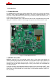
1 Introduction 1.1 Product Overview FSS MB9BF506R EV-Board (PN: FSSDC-9B506-EVB) provides an economical and simple means for study usage for MB9B506 series MCU. The board compatible with both 3.3 and 5V system contains abundant external resources (LCD, buttons, UART, Nand Flash, CAN…) to demonstrate MCU periphery function. It also provides standard 20 pin JTAG interface, which is both compatible with IAR and Keil debug tool. In addition, it allows On-board programming with both USB and UART mode.
The size of on-chip memory can be configured according to different part number and the package is available in LQFP and BGA, shown in following table. Product Flash SRAM MB9BF500N/R 256kB 32kB MB9BF504N/R 256kB 32kB MB9BF505N/R 384kB 48kB MB9BF506N/R 512kB 64kB Package N: LQFP-100 R: LQFP-120 N: LQFP-100/BGA-112 R: LQFP-120 N: LQFP-100/BGA-112 R: LQFP-120 N: LQFP-100/BGA-112 R: LQFP-120 Table 1-1: Product List 1.
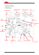
2 Hardware Setting 2.
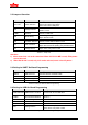
2.2 Jumpers Overview Jumper Name Function J101-J103*1 Power selection J104*2 Voltage selection J-USBJ-USB+ USB Host/Function selection J105 Mode setting J106 Oscillator Selection J107 P22 connection J701 Voltage division Setting Short J101: select external power Short J102: select JTAG power Short J103: select USB power Short 1,2: 5V Short 2,3: 3.
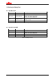
2.5 Setting for Debug Tool Use IAR J-Link Part Number 20PIN-JTAG Function JTAG connctor J101-J103 Power selection J104 Voltage selection J105 Mode setting Setting Connect with J-Link Short J101: select external power Short J102: select JTAG power Short J103: select USB power Short 1,2: 5V Short 2,3: 3.
3 Flash On-Board Programming There are two ways to program the on-chip Flash of MB9BF506 series MCU: UART OnBoard Programming and USB On-Board Programming. 3.1 On-Board Programming via UART First check the hardware setting as introduced by section 2.3. Install the UART programmer: PCWFM3_V01L01. (It can be downloaded on the web) Open it, set the parameter as shown in following figure, and select Hex file. Click Full Operation. Press reset key in the board, and the programming will start.
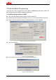
3.2 On-Board Programming via USB First check the hardware setting as introduced by section 2.4. After connect with PC via USB cable, the EVB can be identified as a USB device. Check the COM port for this USB port in the device manager. Install the USB programmer: USBDW_V01L03. (It can be downloaded on the web) Open it, set the parameter as shown in following figure, and select Hex file. Click Full Operation.
Press reset key on the board. Programming will start.
4 Sample Code The sample codes for FSSDC-9B596-EV board are listed as following table.
4.1 UART Hardware Setting Connect UART-2 with PC via RS232 cable Flowchart Usage Figure 4-1: UART Sample Code Flowchart 1) Open a COM assistant software, make following setting, and open COM port Figure 4-2: COM Assistant Setting 2) Open UART sample code and run it, user can watch a string on the COM assistant window. Then send character to EV-board, the character can be received.
Figure 4-3: Send UART Data From PC Side 15
4.2 Nand Flash Hardware Setting None Flowchart Start Initial external bus (Use CS7 area, 8 bit data width) Erase page 11 of block 0 Erase page 20 of block 100 Read Flash ID Write data into page 11 of block 0 Write data into page 20 of block 100 Read data from page 11 of block 0 Read data from page 20 of block 100 End Figure 4-4: Nand Flash Sample Code Flowchart Usage 1) Open Nand Flash sample project, and start debug.
Usage 1) Open Nand Flash sample project, and start debug. 2) Use “step over” to debug, and watch local variable “sec”, “min”, “hour”. 4.4 CAN Hardware Setting Connect 2 EV-board with CAN interface, as following figure.
4.5 USB Function Hardware Setting ¾ Check if 1,2 of J-USB- and J-USB+ short ¾ Check J701 (Short: 5V, Open: 3.3V) ¾ Connect with PC via USB cable Flowchart The following flowchart illuminates the procedure to implement a USB mouse, it is not a certain flow of a function, but provides a clue to study and understand the sample code.
4.6 USB Host Hardware Setting ¾ Check if 2,3 of J-USB- and J-USB+ short ¾ Connect with a USB mouse Flowchart The following flowchart illuminates the procedure to implement USB host function, which can catch the position of a USB mouse, it is not a certain flow of a function, but provides a clue to study and understand the sample code.
4.
5 Debug Tool and IDE FSS MB9BF506R EV-Board supports both Keil U-Link-ME and IAR J-Link for debug shown as following. Figure 5-1: J-Link Overview Figure 5-2: U-Link Overview The U-Link-me should be used with Keil uVision 4 which can be downloaded freely from following web. https://www.keil.com/update/sw/RVMDK/4.20 The J-Link should be used with IAR Embedded Workbench which can be downloaded freely from following web. http://www.iar.com/website1/1.0.1.
5.1 Debug with J-Link in IAR EWARM Workbench The sample code can be debugged in IAR EWARM Workbench with J-Link. The following figure shows basic debug window.
2) Select a project (eww file) Figure 5-5: Select a Project 3) Click “Project | Rebuild All” Figure 5-6:Rebuild All 23
4) Click “Download and Debug” Figure 5-7:Click Download and Debug 5) Use following tool bar to debug Figure 5-8: Debug Tool Bar The sample codes support both Flash and RAM debug in IAR EWARM Workbench, if Flash debug is used, the code is programmed into MB9BF506 Flash. If RAM debug is used, the code only runs in RAM area, and after power off, the code will not be stored, but the RAM debug will be faster than Flash debug.
2) Don’t select “Use macro files” in “Debugger|Setup” table. 3) Set Flash loader file path ($TOOLKIT_DIR$\config\flashloader\Fujitsu\MB9BF506.board) in “Debug|Download” table.
Setting for RAM Debug 1) Check the configuration file path ($PROJ_DIR$\config\mb9bf506_ram.icf) in Linker table. 2) Select “Use macro files” in “Debugger|Setup” table.
3) Don’t use Flash loader file. Figure 5-14: Flash Loader File Disabled If user need to program the hex file into Flash via UART or USB programmer, a hex file need to be produced first. How to Make a HEX File 1) Use Flash debug 2) Select “Generate additional output” in “Output Converter” table. 3) User can find the generated file in path (..
5.2 Debug with U-Link ME in Keil uVision4 The sample code can also be debugged in Keil μVersion4 with U-Link. The following figure shows basic debug window.
2) Select a project (uvproj file) 3) Rebuild all 4) Start debug Figure 5-18: Select a Project Figure 5-19: Rebuild All Files Figure 5-20: Start Debug 29
5) Use following tool bar to debug Figure 5-21: Debug Tool Bar The sample codes support both Flash and RAM debug in Keil uVison 4, if Flash debug is used, the code is programmed into MB9BF506 Flash. If RAM debug is used, the code only runs in RAM area, and after power off, the code will not be stored, but the RAM debug will be faster than Flash debug. Setting for Flash Debug 1) Set ROM address in Flash area.
2) Don’t use initialization file.
Setting for RAM Debug 1) Set ROM address in Code SRAM area. (0x1fff8000-0x1fffffff) 2) Set initialization file path. (..\Debug_RAM.
3) Don’t Check “Update Target before Debugging” checkbox Figure 5-27: Select Update Target Before Debugging If user need to program the hex file into Flash via UART or USB programmer, a hex file need to be produced first. How to Make a HEX File 1) Check “Create HEX File” checkbox (This file is Intel Format HEX) 2) User can find the generated file in path “..
6 Materials Download The following materials can be downloaded from below web. http://www.fujitsu.com/cn/fss/events/contest/2010/index_download.