
Datasheet


Quad-Core Intel® Xeon® Processor 5300 Series Datasheet 103
Thermal Specifications
6.4.1.2 Processor Thermal Data Sample Rate and Filtering
The DTS provides an improved capability to monitor device hot spots, which inherently
leads to more varying temperature readings over short time intervals. The DTS sample
interval range can be modified, and a data filtering algorithm can be activated to help
moderate this. The DTS sample interval range is 82 ms (default) to 20 ms (max). This
value can be set in BIOS.
To reduce the sample rate requirements on PECI and improve thermal data stability vs.
time the processor DTS also implements an averaging algorithm that filters the
incoming data. This is an alpha-beta filter with coefficients of 0.5, and is expressed
mathematically as: Current_filtered_temp = (Previous_filtered_temp / 2) +
(new_sensor_temp / 2). This filtering algorithm is fixed and cannot be changed. It is on
by default and can be turned off in BIOS.
Host controllers should utilize the min/max sample times to determine the appropriate
sample rate based on the controller's fan control algorithm and targeted response rate.
The key items to take into account when settling on a fan control algorithm are the DTS
sample rate, whether the temperature filter is enabled, how often the PECI host will
poll the processor for temperature data, and the rate at which fan speed is changed.
Depending on the designer’s specific requirements the DTS sample rate and alpha-beta
filter may have no effect on the fan control algorithm.
6.4.2 PECI Specifications
6.4.2.1 PECI Device Address
The PECI device address for socket 0 is 0x30 and socket 1 is 0x31. Please note that
each address also supports two domains (Domain 0 and Domain 1). For more
information on PECI domains, please refer to the Platform Environment Control
Interface Specification.
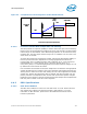
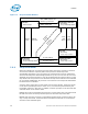
Figure 6-9. Conceptual Fan Control Diagram For A PECI-Based Platform
Fan Speed
(RPM)
(not intended to depict actual implementation)
Max
Min
Temperature
PECI = -10
PECI = -20
TCC Activation
Temperature
T
CONTROL
Setting
PECI = 0
Fan Speed
(RPM)
(not intended to depict actual implementation)
Max
Min
Temperature
PECI = -10
PECI = -20
TCC Activation
Temperature
T
CONTROL
Setting
PECI = 0