
Datasheet

Boxed Processor Specifications
122 Quad-Core Intel® Xeon® Processor 5300 Series Datasheet
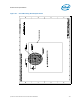
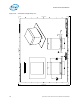
The fan power header on the baseboard must be positioned to allow the fan heat sink
power cable to reach it. The fan power header identification and location must be
documented in the suppliers platform documentation, or on the baseboard itself. The
baseboard fan power header should be positioned within 177.8 mm [7 in.] from the
center of the processor socket.
Note:
1. System board should pull this pin up to Vcc with a resistor
Note: System board should provide an open drain / open collector for pin 4. Fan will pull this pin up to a
specific voltage (5.25V max).
8.3.2 Boxed Processor Cooling Requirements
As previously stated the boxed processor will be available in two product
configurations. Each configuration will require unique design considerations. Meeting
the processor’s temperature specifications is also the function of the thermal design of
the entire system, and ultimately the responsibility of the system integrator. The
processor temperature specifications are found in Section 6 of this document.
Table 8-1. PWM Fan Frequency Specifications for 4-Pin Active CEK Thermal Solution
Description Min Frequency Nominal Frequency Max Frequency Unit
PWM Control
Frequency Range
21,000 25,000 28,000 Hz
Table 8-2. Fan Specifications for 4-Pin Active CEK Thermal Solution
Description1 Min
Typ
Steady
Max
Steady
Max
Startup
Unit
+12 V: 12 volt fan power supply 10.8 12 12 13.2 V
IC: Fan Current Draw N/A 1 1.25 1.5 A
SENSE: SENSE frequency 2 2 2 2
Pulses per fan
revolution
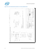
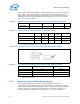
Figure 8-11. Fan Cable Connector Pin Out for 4-Pin Active CEK Thermal Solution
Table 8-3. Fan Cable Connector Pin Out for 4-Pin Active CEK Thermal Solution
Pin Number Signal Color
1 Ground Black
2 Power: (+12 V) Yellow
3 Sense: 2 pulses per revolution Green
4 Control: 21 KHz-28 KHz Blue