
Datasheet

Quad-Core Intel® Xeon® Processor 5300 Series Datasheet 39
Electrical Specifications
Notes:
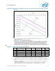
1. The V
CC_MIN
and V
CC_MAX
loadlines represent static and transient limits. Please see Section 2.13.2 for VCC
overshoot specifications.
2. Refer to Table 2-12 for processor VID information.
3. Refer to Table 2-14 for V
CC
Static and Transient Tolerance.
4. The load lines specify voltage limits at the die measured at the VCC_DIE_SENSE and VSS_DIE_SENSE
lands and the VCC_DIE_SENSE2 and VSS_DIE_SENSE2 lands. Voltage regulation feedback for voltage
regulator circuits must also be taken from processor VCC_DIE_SENSE and VSS_DIE_SENSE lands and
VCC_DIE_SENSE2 and VSS_DIE_SENSE2 lands. Refer to the Voltage Regulator Module (VRM) and
Enterprise Voltage Regulator Down (EVRD) 11.0 Design Guidelines for socket load line guidelines and VR
implementation. Please refer to the appropriate platform design guide for details on VR implementation
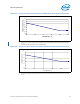
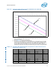
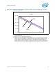
Figure 2-10. Quad-Core Intel® Xeon® Processor X5365 Series V
CC
Static and Transient
Tolerance Load Lines
VID - 0.000
VID - 0.050
VID - 0.100
VID - 0.150
VID - 0.200
VID - 0.250
0 5 10 15 20 25 30 35 40 45 50 55 60 65 70 75 80 85 90 95 100 105 110 115 120 125 130 135 140 145 150
Icc [A]
Vcc [V]
V
CC
Ma x imu m
V
CC
Typical
V
CC
Min imu m