
Datasheet

Quad-Core Intel® Xeon® Processor 5300 Series Datasheet 51
Mechanical Specifications
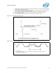
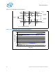
3.2 Processor Component Keepout Zones
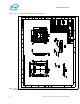
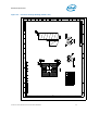
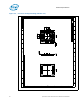
The processor may contain components on the substrate that define component
keepout zone requirements. A thermal and mechanical solution design must not intrude
into the required keepout zones. Decoupling capacitors are typically mounted to either
the topside or landside of the package substrate. See Figure 3-4 for keepout zones.
3.3 Package Loading Specifications
Table 3-1 provides dynamic and static load specifications for the processor package.
These mechanical load limits should not be exceeded during heatsink assembly,
mechanical stress testing or standard drop and shipping conditions. The heatsink
attach solutions must not include continuous stress onto the processor with the
exception of a uniform load to maintain the heatsink-to-processor thermal interface.
Also, any mechanical system or component testing should not exceed these limits. The
processor package substrate should not be used as a mechanical reference or load-
bearing surface for thermal or mechanical solutions.
Notes:
1. These specifications apply to uniform compressive loading in a direction perpendicular to the IHS top
surface.
2. This is the minimum and maximum static force that can be applied by the heatsink and retention solution
to maintain the heatsink and processor interface.
3. These specifications are based on limited testing for design characterization. Loading limits are for the
LGA771 socket.
4. Dynamic compressive load applies to all board thickness.
5. Dynamic loading is defined as an 11 ms duration average load superimposed on the static load
requirement.
6. Test condition used a heatsink mass of 1 lbm with 50 g acceleration measured at heatsink mass. The
dynamic portion of this specification in the product application can have flexibility in specific values, but the
ultimate product of mass times acceleration should not exceed this dynamic load.
7. Transient bend is defined as the transient board deflection during manufacturing such as board assembly
and system integration. It is a relatively slow bending event compared to shock and vibration tests.
8. For more information on the transient bend limits, please refer to the MAS document entitled
Manufacturing with Intel® Components using 771-land LGA Package that Interfaces with the Motherboard
via a LGA771 Socket.
9. Refer to the Quad-Core Intel® Xeon® Processor 5300 Series Thermal/Mechanical Design Guidelines for
information on heatsink clip load metrology.
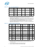
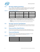
Table 3-1. Package Loading Specifications
Parameter
Board
Thickness
Min Max Unit Notes
Static Compressive Load 1.57 mm
0.062”
80
18
311
70
N
lbf
1,2,3,9
2.16 mm
0.085”
111
25
311
70
N
lbf
2.54 mm
0.100”
133
30
311
70
N
lbf
Dynamic Compressive
Load
NA NA 311 N (max
static
compressive
load) + 222 N
dynamic loading
70 lbf (max
static
compressive
load) + 50 lbf
dynamic loading
N
lbf
1,3,4,5,6
Transient Bend Limits 1.57 mm
0.062”
NA 750 me 1,3,7,8