
User guide

Interface
D-9
User's Manual
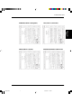
TD
RD
DSR
DTR
RTS
CTS
CD
SG
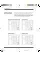
Host Printer
(Pin 2)
(Pin 3)
(Pin 6)
(Pin 20)
(Pin 4)
(Pin 5)
(Pin 8)
(Pin 7)
TD
RD
DSR
DTR (RC)
RTS
CTS
CD
SG
#
#
#
#
#
# indicates an open wire.
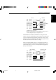
Wire q is unnecessary for the DTR (or RC) protocol.
Some computers may not require wire w.
q
w
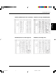
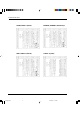
DSR-enabled control enables communication using an RS-232C
interface. The CTS and DSR input control signals are enabled; CD is
ignored. DSR must be high when the printer receives data. If the
printer has data to be transmitted to the computer, the printer trans-
mits the data when both DSR and CTS are high.
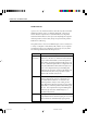
When using DSR-enabled control, use a straight-through cable to
connect to a DCE (data communications equipment) device. Use a
null-modem cable to connect to a DTE (data terminal equipment)
device, as shown below.
TD
RD
DSR
DTR
RTS
CTS
CD
SG
Host (DTE) Printer (DTE)
(Pin 2)
(Pin 3)
(Pin 6)
(Pin 20)
(Pin 4)
(Pin 5)
(Pin 8)
(Pin 7)
TD
RD
DSR
DTR
RTS
CTS
CD
SG
INTERFACE INFORMATION
#D Appendix D 2000.09.20, 2:47 PM9