
Printer User's Manual


Cable Wiring
C-10 User’s Manual
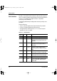
The printer allows two types of serial communication control: DSR
enabled and DSR disabled. The type used is determined by processor
requirements and affects the way the interface cable is wired. To select
between DSR-enabled and DSR-disabled control, use the printer
HARDWRE function (see “Changing Hardware Options” on page
8-24 and in subsequent sections).
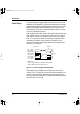
DSR-disabled control offers simpler cabling and communication than
DSR-enabled control. It can be used for interfacing with an IBM or
most other PCs. With DSR-disabled control, input control signals
DSR, CTS, and CD are always considered high, regardless of their
actual status. Therefore, a wire connection for these pins is not
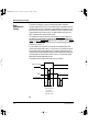
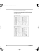
required. The following figure below shows the wiring required for
connection to an IBM PC.
Figure C–1 Cable wiring (DSR disabled control)
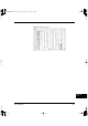
DSR-enabled control enables communication with an RS-232C
interface. The CTS and DSR input control signals are enabled; CD is
ignored. DSR must be high when the printer receives data. If the
printer has data to be transmitted, it transmits data immediately when
both DSR and CTS are high.
Cable Wiring
TD
RD
DSR
DTR
RTS
CTS
CD
SG
(pin 2)
(pin 3)
(pin 6)
(pin 20)
(pin 4)
(pin 5)
(pin 8)
(pin 7)
TD
RD
DSR
DTR (RC)
RTS
CTS
CD
SG
#
#
#
#
#
# Open wire
Wire q is unnecessary for the DTR (or RC) protocol.
Some computers may not require wire w.
Processor Printer
q
w
DL6400/6600 Book Page 10 Thursday, September 21, 2000 7:52 PM