Operating Manual ESPRIMO E5xx/E7xx/E9xx System
Thank you for buying an innovative product from Fujitsu. Latest information about our products, useful tips, updates etc. is available on our website: "http://www.fujitsu.com/fts/" You can receive automatic driver updates from: "http://support.ts.fujitsu.com/download" Should you have any technical questions, please contact: our Hotline/Service Desk (see Service Desk list or from the Internet at: "http://support.ts.fujitsu.
Published by Fujitsu Technology Solutions GmbH Mies-van-der-Rohe-Straße 8 80807 Munich, Germany Contact http://www.fujitsu.com/fts/ Copyright © Fujitsu Technology Solutions GmbH 2012. All rights reserved. Publication Date 10/2012 Order No.
ESPRIMO E5xx/E7xx/E9xx Operating Manual Your ESPRIMO 5 Ports and operating elements 7 Important notes 10 Getting started 13 Operation 23 Problem solutions and tips 31 System expansions 35 Technical specification 66 Index 67
Remarks Information on the product description meets the design specifications of Fujitsu and is provided for comparison purposes. Several factors may cause the actual results to differ. Technical data is subject to change without prior notification. Fujitsu rejects any responsibility with regard to technical or editorial mistakes or omissions.
Contents Contents Your ESPRIMO . . . . . . . . . . . . . . . . . . . . . . . . . . . . . . . . . . . . . . . . . . . . . . . . . . . . . . . . . . . . . . . . . . . . . . . . . Validity of the Reference Manual . . . . . . . . . . . . . . . . . . . . . . . . . . . . . . . . . . . . . . . . . . . . . . . . . . . . . . . . . Notational conventions . . . . . . . . . . . . . . . . . . . . . . . . . . . . . . . . . . . . . . . . . . . . . . . . . . . . . . . . . . . . . . . . . .
Contents Problem solutions and tips . . . . . . . . . . . . . . . . . . . . . . . . . . . . . . . . . . . . . . . . . . . . . . . . . . . . . . . . . . . . Help if problems occur . . . . . . . . . . . . . . . . . . . . . . . . . . . . . . . . . . . . . . . . . . . . . . . . . . . . . . . . . . . . . . . . . . . Troubleshooting . . . . . . . . . . . . . . . . . . . . . . . . . . . . . . . . . . . . . . . . . . . . . . . . . . . . . . . . . . . . . . . . . . . . . . . . .
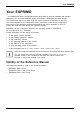
Your ESPRIMO Your ESPRIMO Overview ... is available with various configuration levels which differ in terms of hardware and software equipment. You can install additional drives (for example a DVD drive) and other boards. This manual tells you how to start using your device and how to operate it in daily use. This manual applies for all configuration levels. Depending on the chosen configuration level, some of the hardware components described may not be available on your PC.
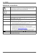
Your ESPRIMO Notational conventions Pay particular attention to text marked with this symbol. Failure to observe these warnings could pose a risk to health, damage the device or lead to loss of data. The warranty will be invalidated if the device becomes defective through failure to observe these warnings. Indicates important information for the proper use of the device.
Ports and operating elements Ports and operating elements Ports This chapter presents the individual hardware components of your device. This will provide you with an overview of the ports and operating elements on the device. Please familiarise yourself with these components before starting to work with your device.
Ports and operating elements Device with alternating voltage socket, monitor socket and Primary Resume Button.
Ports and operating elements Device with alternating voltage socket and monitor socket 4 3 1 2 1 = Alternating voltage socket (AC IN) 2 = Monitor socket 3 = Ports for external devices (device-dependent) Fujitsu 4 = Slot covers (shown here: low-profile boards) 9
Important notes Important notes Notes Importantnotes In this chapter you will find information regarding safety which it is essential to take note of when working with your device. Safety information Note Safetyinformation Please note the information provided in the "Safety/regulations" manual and in the following safety notes.
Important notes Cleaning the device System unit,see Device Retransportation Transportation Device, Turn off all power and equipment switches and disconnect the power plug from the mains outlet. Do not clean any interior parts yourself, leave this job to a service technician. Do not use any cleaning agents that contain abrasives or may corrode plastic (alcohol, thinner or acetone). Never clean the device with water! Water entering into the device could present a serious risk to users (e.g. electric shock).
Important notes FCC Compliance Statement If the device complies with the FCC regulations, the FCC sign can be found on the type rating plate. FCC Class B Compliance Statement DOC (INDUSTRY CANADA) NOTICES Notice to Users of Radios and Television : This class B digital apparatus complies with Canadian ICES-003. The following statement applies to the products covered in this manual, unless otherwise specified herein. The statement for other products will appear in the accompanying documentation.
Getting started Getting started Gettingstarted Please observe the safety information in the "Important notes", Page 10 chapter. Unpacking and checking the delivery It is recommended not to throw away the original packaging material! It may be required for reshipment at some later date. Packaging, Contentsofdelivery Packaging ► ► ► ► Unpack all the individual parts. Check the contents of the package for any visible damage caused during transport.
Getting started Setting up the device Device, Ergonomic Videoworkstation When installing your device, please read the recommendations and safety notes in the "Safety" manual. We recommend that you place your device on a surface with good anti-slip qualities. In view of the multitude of different finishes and varnishes used on furniture, it is possible that the rubber feet will mark the surface they stand on. Depending on the location of your device, bothersome vibrations and noises may occur.
Getting started Vertical operating position (optional) Use the optional rubber feet or base feet if you wish to operate the device in the vertical operating position. The set-up direction is compulsory: The ON/OFF switch must be at the top to ensure sufficient ventilation. Operation in a vertical operating position is not permitted in Taiwan.
Getting started Using the device with rubber feet (optional) Proceed as follows to operate the device in the vertical operating position using the rubber feet: ► If necessary, disconnect the cables connected to the device. ► First, position the casing vertically so that the ON/OFF switch is located at the bottom. ► Pull off the foil from the rubber feet that you will find in the accessories package. 40 mm 1 1 1 1 6 mm ► Affix the rubber feet (1) to the outside of the casing.
Getting started Connecting external devices Read the documentation on the external device before connecting it. With the exception of USB devices, always remove all power plugs before connecting external devices! Do not connect or disconnect cables during a thunderstorm. Always take hold of the actual plug. Never unplug a cable by pulling the cable itself. Connect and disconnect the cables in the order described below. Connecting the cables ► Turn off all power and equipment switches.
Getting started Ports on the device Device, Externaldevices, Interfaces The ports are located on the front and back of the device. The ports available on your device depend on the configuration level you have selected. The standard ports are marked with the symbols shown below (or similar). Detailed information on the location of the ports is provided in the manual for the mainboard.
Getting started Connecting the mouse You can connect a USB mouse or a PS/2 mouse to your device. Connecting, Mouse, Connecting a USB mouse ► Connect the USB mouse to one of the USB ports on the device. USBport USBport, Connecting a PS/2 mouse The PS/2 mouse is only detected by the device if you connect the mouse when the device is switched off and then switch the device on again. ► Switch your device off.
Getting started Connecting external devices to the serial interface Devices, Externaldevices, Serialinterface, Serialinterface External devices can be connected to the serial interface (e.g. a printer or modem). ► Connect the data cable to the external device. ► Connect the data cable to the corresponding serial interface. For an exact description of how to connect external devices to the corresponding port, please see the external device documentation.
Getting started Switching on for the first time: installing the software Software, Installing, Once the installation has been started the device must not be switched off, unless the installation has been completed. During installation, the device may only be rebooted when you are requested to do so! The installation will otherwise not be carried out correctly and the contents of the hard disk must be completely restored.
Getting started Installing the software ► During installation, follow the on-screen instructions. ► If anything is unclear regarding the data you are asked to input, read the online Help in your operating system. Installing, Software, You will find more information on the system, as well as drivers, utilities and updates on the "Drivers & Utilities" DVD and on the Internet at "http://www.fujitsu.com/fts/support".
Operation Operation Switch the device on ► If necessary, switch the monitor on (see the operating manual for the monitor). ► Switch on the device using the main power switch located on the rear of the device (if present). ► Press the ON/OFF switch on the front of the device. The power indicator glows and the device starts. Monitor, Device, Switching on a device when the lithium battery is discharged (0-Watt devices) A 0-Watt device consumes no current when it is switched off and in the quiescent state.
Operation Switching off the device ► Shut down the operating system in the proper way. ► If the operating system does not automatically switch the device into energy-saving mode or switch it off, press the ON/OFF switch. Warning, this could lead to a loss of data! ► Switch the device off at the main switch (if present).
Operation Indicators on the device Device Indicators, The indicators are on the front of the casing. Which indicators are available on your device depends on the configuration level you have selected. 1 No. Indicator 1 Indicator for optional components, e.g. SmartCard reader 2 Drive indicator 3 Power-on indicator 2 3 4 Description The indicator lights up when optional components, e.g. SmartCard reader, are accessed. The indicator lights up when the CD-ROM or DVD drive in the device is accessed.
Operation Keyboard Alphanumeric Keyboard, Keyboard Cursor Function Keys, Numeric keys keypad keys keypad The illustrated keyboard is an example and may differ from the model you use. 1 2 3 1 = Function keys 2 = On/off switch (optional) 3 = Alphanumeric keypad 4 5 4 = Cursor keys 5 = Numeric keypad (calculator keypad) Important keys and keyboard shortcuts Keyboardshortcuts Keys The description of the following keys and keyboard shortcuts applies to Microsoft operating systems.
Operation Key / key combination Description Windows key (device-dependent: variant 1) Keys, calls up the Windows Start menu. Keys, Menu key (device-dependent: variant 1) calls up the menu for the marked item (Windows). Windows key (device-dependent: variant 2) The Windows key switches between the start screen and the application which was used last. Menu key (device-dependent: variant 2) The Menu key opens the menu for the active application.
Operation Settings in BIOS Setup System BIOS Setup, Setup, Setup settings, In BIOS Setup, you can set the system functions and the hardware configuration of the device. When the PC is delivered, the default entries are valid (see "BIOS Setup" manual or manual for the mainboard). You can customise these settings to your requirements in the BIOS Setup.
Operation Mechanical casing lock (optional) Lock lock Casing mechanicallock With the casing lock you can mechanically lock the casing to prohibit unauthorised persons from opening it. The keys can be found on the rear panel of your device. 2 1 Unlocking the casing ► Turn the key in the direction of the arrow (1). Locking the casing ► Turn the key in the direction of the arrow (2).
Operation Access authorisation via SmartCard Accesspermission,SmartCard Securityfunctions, In systems equipped with a SmartCard reader, access can be restricted to those users who have a corresponding SmartCard. Operating the SmartCard reader (optional) Operation is not permitted in Taiwan. ► Connect the external SmartCard reader to your system as described in the instructions for the SmartCard reader. After the device is switched on, you will be prompted to insert your SmartCard.
Problem solutions and tips Problem solutions and tips Comply with the safety information in the "Safety" manual and the chapter "Getting started", Page 13, when attaching or detaching cables. If a fault occurs, try to rectify it in accordance with the measures described in the following documents: • • • • in in in in this chapter the documentation relating to the peripheral devices the Help sections for the individual programs the documentation for the operating system in use.
Problem solutions and tips The device cannot be switched off with the ON/OFF switch. Cause Remedy System crash ► Keep the on/off switch pressed for at least 4 seconds until the machine switches off. Caution: This can lead to a loss of data! This procedure does not allow the operating system to shut down in an orderly way. The next time the system is started there may well be error messages. The device cannot be switched on with the ON/OFF switch (0-Watt devices) Cause The lithium battery is discharged.
Problem solutions and tips Cause Monitor cable not connected Incorrect setting for the monitor Remedy ► Switch off the monitor and the device. ► Check that the monitor cable is properly connected to the device and monitor. ► Switch on the monitor and the device. ► Restart the system. ► Press F8 while the system is booting. ► Start the system in Safe Mode. ► Set up the monitor as described in the documentation for your operating system and monitor.
Problem solutions and tips Error messages on the screen Error messages and their explanations are provided: • • in the technical manual for the mainboard in the documentation for the programs used Installing new software When installing programs or drivers, important files may be overwritten and modified. To be able to access the original data in the event of any problems following installation, you should backup your hard disk prior to installation.
System expansions System expansions System expansion Device, Upgrades, Servicing Components Repairs to the device must only be performed by qualified technicians. Incorrect repairs may greatly endanger the user (electric shock, fire risk) and will invalidate your warranty. After consulting the Hotline/Help Desk, you may remove and install the components described in this manual yourself.
System expansions Information about boards Take care with the locking mechanisms (catches and centring pins) when you are replacing boards or components on boards. Note that some components on the mainboard may be very hot if the device was in use shortly before the casing was removed. To prevent damage to the board or the components and conductors on it, please take care when you insert or remove boards. Make sure expansion boards are inserted straightly.
System expansions Removing the casing cover ► Switch the device off. The device must not be in the energy-saving mode! ► Remove any plugged-in wires which are in the way. 3 2 1 ► Slide the retaining mechanism in the direction of the arrow (1). ► Slide the casing cover a small distance in the direction indicated by the arrow (2) and lift it off (3).
System expansions Reattaching the casing cover. 1 2 ► Place the casing cover onto the casing (1) and slide it as far as possible in the direction indicated by the arrow (2). The casing cover will click into place automatically, without any need to move the retaining mechanism. ► Connect the cables to the device.
System expansions Opening the drive cage Drive cage ► Remove the casing cover (see Chapter "Removing the casing cover", Page 37). When folding out the drive cage, ensure that you do not fold it out to an angle greater than 90°, as shown in the diagram. 1 ► Fold out the drive cage (1).
System expansions Closing the drive cage Drive cage Take care not to trap any cables when folding the drive cage into the closed position. Make sure that the retaining mechanism on the memory module is closed. 1 ► Fold the drive cage to the closed position (1). ► Fit the casing cover back onto the casing (see Chapter "Reattaching the casing cover.", Page 38).
System expansions Installing and removing the accessible 51/4 inch drive Fitting the drive cover for the 5 1/4 inch drive In order to use the locking function for the accessible 51/4 drive, the corresponding drive cover must be fitted to the drive before the drive is installed in the casing. Proceed as follows: The drive cover can be found either on the drive place holder or on the installed drive. ► Remove the casing cover (see Chapter "Removing the casing cover", Page 37).
System expansions Installing an accessible drive ► Remove the casing cover (see Chapter "Removing the casing cover", Page 37). 2 1 ► If no drive is installed, then remove the drive placeholder by sliding the retaining mechanism in the direction of the arrow (1). ► Pull the drive out of the drive cage in the direction of the arrow (2). Do not dispose of the drive placeholder.
System expansions 1 ► Slide the new drive into the drive cage (1) until it engages. ► Connect the cables to the drive. Make sure the polarity is correct. ► Fit the casing cover back onto the casing (see Chapter "Reattaching the casing cover.", Page 38). It may be necessary to modify the entry for the drive in the BIOS Setup.
System expansions Removing an accessible drive ► Remove the casing cover (see Chapter "Removing the casing cover", Page 37). ► Disconnect any cables connected to the drive. 2 1 ► Slide the retaining mechanism in the direction of the arrow (1). ► Pull the drive out of the drive cage in the direction of the arrow (2). ► If you do not install a new drive, then a drive placeholder must be installed in the drive bay to prevent any foreign objects from entering the casing.
System expansions Installing/removing a SmartCard reader, WLAN module or multicard reader (optional, 3½ inch) Operation of the module is not permitted in Taiwan. It is possible to install a SmartCard and/or WLAN module for wireless LAN (Local Area Network) in the drive bay for the 3½ inch drive. The SmartCard reader and WLAN module can be installed together in the same module carrier. The two boards can also be installed individually without the second board.
System expansions Attaching the WLAN module to the module carrier ► With the component side facing downwards, slide the WLAN module in the direction of the arrow (1) into the guide on the module holder (a). ► Fasten the WLAN module in place with the screw (2). 2 a a 1 Screwing the SmartCard reader onto the module holder 2 2 a a 46 ► Push the SmartCard reader - with the component side facing downwards - into the guide on the module holder (a) in the direction of the arrow (1).
System expansions Installing a multicard reader or module carrier containing a SmartCard reader and/or WLAN module 1 ► Slide the module carrier/multicard reader into the drive casing in the direction of the arrow (1). ► Fold out the drive cage (see Chapter "Opening the drive cage", Page 39). 1 1 ► Secure the module carrier/multicard reader with the screws (1). ► Connect the cables to the module carrier/multicard reader. Make sure the polarity is correct.
System expansions Removing the module carrier with SmartCard reader and/or WLAN module or multicard reader ► Disconnect any cables connected to the module carrier/multicard reader. 1 1 ► Remove the screws (1) from the module carrier/multicard reader. ► Fold the drive cage back into the closed position (see Chapter"Closing the drive cage", Page 40). 1 ► Slide the module carrier/multicard reader out of the casing in the direction of the arrow (1).
System expansions Removing the SmartCard reader from the module holder 1 1 ► Undo the screws (1). ► Pull the SmartCard reader out of the module holder in the direction of the arrow (2). Removing the WLAN module from carrier 1 Fujitsu ► Loosen the screw (1). ► Pull the WLAN module out of the module carrier in the direction of the arrow.
System expansions Completing installation/removal of components 1 1 ► Fasten the cover plate to the drive bay for the 3½-inch drive (1). ► Fasten the blanking plate onto the drive bay in the casing cover. ► Fit the casing cover back onto the casing (see Chapter "Reattaching the casing cover.", Page 38).
System expansions Installing and removing the hard disk drive Installing a hard disk drive ► Remove the casing cover (see Chapter "Removing the casing cover", Page 37). EasyChange rails for the hard disk drive are located in the drive cage. ► Fasten the EasyChange rails to the side of the hard disk drive by inserting the upper pins of the EasyChange rail in the corresponding holes on the hard disk.
System expansions 1 ► Slide the hard disk drive with the EasyChange rails fitted into the drive cage in the direction of the arrow (1). Check that the component side of the hard disk drive faces downwards towards the base of the casing. ► Connect the cables to the hard disk drive. ► Fit the casing cover back onto the casing (see Chapter "Reattaching the casing cover.", Page 38). It may be necessary to modify the entry for the drive in the BIOS Setup accordingly.
System expansions Removing the hard disk drive ► Remove the casing cover (see Chapter "Removing the casing cover", Page 37). ► Disconnect any cables connected to the hard disk drive. 2 1 1 ► Slightly press together the EasyChange rails on the hard disk drive (1) and pull the hard disk drive out of the drive cage in the direction of the arrow (2).
System expansions ► Pull the EasyChange rails off the hard disk drive. ► If you no longer need the EasyChange rails, secure them again at their location in the drive cage. ► Fit the casing cover back onto the casing (see Chapter "Reattaching the casing cover.", Page 38). It may be necessary to modify the entry for the drive in the BIOS Setup.
System expansions Installing and removing boards Depending on the device variant, your device will be equipped to accept either high-profile boards or low-profile boards. Installing and removing high-profile boards (device-dependent) You can install additional modules in order to increase the performance of your machine. The number, position and arrangement of the board slots on the mainboard can be found in the manual for the mainboard. Boards may already be installed on shipment.
System expansions Removing a slot cover. ► Undo the screw (1, optional). ► Pull the slot cover out of the slot (2). 1 2 Do not throw away the slot cover. For cooling, protection against fire and in order to comply with EMC regulations, you must refit the slot cover if you remove the board.
System expansions Installing a board ► Push the board into the slot (1) until it engages. ► Tighten the screw (2, optional). 2 1 ► If necessary, connect the cables to the board. If you have installed or removed a board, please check the relevant PCI slot settings in the BIOS Setup. If necessary, change the settings. Further information is provided in the PCI board documentation. Removing boards ► If necessary, disconnect the cables which are connected to the board. ► Undo the screw (1, optional).
System expansions Reinstalling a slot cover ► Push the slot cover into the slot (1). ► Tighten the screw (2, optional). 2 1 Installing the board cage 2 1 ► Close the retaining mechanism on the board cage (1). ► Insert the board cage into the casing (1). ► Fit the casing cover back onto the casing (see Chapter "Reattaching the casing cover.", Page 38). If you have installed or removed a board, please check the relevant PCI slot settings in the BIOS Setup. If necessary, change the settings.
System expansions Installing and removing low-profile boards (device-dependent) Low-profileboard For every slot there is a slot cover provided. If no board is installed, the slot cover protects the slot. When you install a board, do not discard the corresponding slot cover. For cooling, protection against fire and in order to comply with EMC regulations, you must refit the slot cover if you remove the board.
System expansions Removing a slot cover. ► Undo the screw (1, optional). ► Pull the slot cover out of the slot (2). 1 2 Do not throw away the slot cover. For cooling, protection against fire and in order to comply with EMC regulations, you must refit the slot cover if you remove the board.
System expansions Installing a board ► Push the board into the slot (1) until it engages. ► Tighten the screw (2, optional). 2 1 ► If necessary, connect the cables to the board. If you have installed or removed a board, please check the relevant PCI slot settings in the BIOS Setup. If necessary, change the settings. Further information is provided in the PCI board documentation. Removing boards ► If necessary, disconnect the cables which are connected to the board. ► Undo the screw (1, optional).
System expansions Reinstalling a slot cover ► Push the slot cover into the slot (1). ► Tighten the screw (2, optional). 2 1 Closing the board retaining mechanism 1 ► Fold the board retaining mechanism to the closed position (1). ► Fit the casing cover back onto the casing (see Chapter "Reattaching the casing cover.", Page 38). If you have installed or removed a board, please check the relevant PCI slot settings in the BIOS Setup. If necessary, change the settings.
System expansions Installing and removing heat sinks Removing the heat sink ► Remove the casing cover (see Chapter "Removing the casing cover", Page 37). ► Disconnect the fan cables from the mainboard. ► Undo the screws (1). 1 ► Remove the heat sink from the casing (2). 1 1 2 1 Never operate the device without the heat sink fitted! Reinstall the heat sink before switching on the device.
System expansions Processor, replacing ► ► ► ► ► 64 Remove the casing cover (see Chapter "Removing the casing cover", Page 37). Remove the heat sink (see "Removing the heat sink", Page 63). Upgrade the processor according to the description in the manual for the mainboard. Reinstall the heat sink (see "Installing the heat sink", Page 63). Fit the casing cover back onto the casing (see Chapter "Reattaching the casing cover.", Page 38).
System expansions Replacing the lithium battery In order to permanently save the system information, a lithium battery is installed to provide the CMOS-memory with a current. A corresponding error message notifies the user when the charge is too low or the battery is empty. The lithium battery must then be replaced. Incorrect replacement of the lithium battery may lead to a risk of explosion! The lithium battery may be replaced only with an identical battery or with a type recommended by the manufacturer.
Technical specification Technical specification Electrical data Safety standards complied with: Protection class: Rated voltage range: Rated frequency: Max. rated current: Device with monitor socket: of which Value for monitor socket: Device without monitor socket: Dimensions Width/depth/height: IEC 60950, EN 60950, UL 60950 CSA 22.2 No.60950-1 I 100 V – 240 V 50 Hz – 60 Hz 100 V – 240 V 5.0 A – 2.5 A 100 V – 240 V 2.0 A – 1.0 A 100 V – 240 V 3.5 – 1.5 A 340 mm / 383 mm / 98 mm / 13.39 in x 15.09 in x 3.
Index Index A Access permission, SmartCard Alphanumeric keypad 26 Anti-theft protection 28 Audio input 18 Audio output 18 30 B Base feet 15 Battery 65 BIOS Setup 28 security functions 29 BIOS Setup, configuration 28 settings 28 system settings 28 Board, installing 55 removing 55 Button, ON/OFF switch 26 C Cable, connecting 17 disconnecting 17 Casing Mechanical lock 29 Casing lock 29 Casing mechanical lock 29 Casing, lead-sealing 28 CE marking 11 Chain 28 Components installing/removing 35 Connecting a PS/
Index Interfaces 18 K Kensington Lock 28 Keyboard 26 Keyboard port 18 keyboard shortcuts 27 Keyboard shortcuts 26 Keyboard, alphanumeric keypad connecting 19 cursor keys 26 function keys 26 numeric keypad 26 port 19 Keys 26 Ctrl 27 Ctrl+Alt+Del 27 Keys, Alt Gr 27 Control 27 Ctrl key 27 cursor keys 26 Enter 26 Enter key 26 menu key 27 Num Lock 27 Return 26 shift 27 shift key 27 Start key 27 L LAN port 18 Lead-sealing 28 Line in 18 Line out 18 Lithium battery 63 Lithium battery, replacing 65 Lock 29 Low vo
Index Security functions BIOS Setup 29 Security functions, SmartCard 30 Security measures 28 Serial interface 18, 20 Serial interface, connecting devices 20 settings 20 Servicing 35 Setup, see BIOS Setup 28 Side cover 15 SmartCard reader, operating 30 Software, installing 21–22 System expansion 35 System settings, BIOS Setup 28 System unit, see Device 11 T Transportation Fujitsu U Universal Serial Bus 18 Upgrades Mainboard 63 Upgrades, device 35 USB devices, connecting 20 USB port 19 USB port, connecting