Operating Manual ESPRIMO P4xx / P5xx / PH3xx System
Thank you for buying an innovative product from Fujitsu. Latest information about our products, useful tips, updates etc. is available on our website: "http://www.fujitsu.com/fts/" You can find driver updates at: "http://support.ts.fujitsu.com/download" Should you have any technical questions, please contact: our Hotline/Service Desk (see Service Desk list or from the Internet at: "http://support.ts.fujitsu.
Published by / Contact address in the EU Fujitsu Technology Solutions GmbH Mies-van-der-Rohe-Straße 8 80807 Munich, Germany "http://www.fujitsu.com/fts/" Copyright © Fujitsu Technology Solutions GmbH 2013. All rights reserved. Publication Date 03/2013 Order No.
ESPRIMO P4xx / P5xx / PH3xx Operating Manual Your ESPRIMO 5 Important notes 7 Getting started 11 Operation 19 Troubleshooting and tips 25 System expansions 29 Technical specification 44 Index 45
Remarks Information on the product description meets the design specifications of Fujitsu and is provided for comparison purposes. Several factors may cause the actual results to differ. Technical data is subject to change without prior notification. Fujitsu rejects any responsibility with regard to technical or editorial mistakes or omissions.
Contents Contents Your ESPRIMO . . . . . . . . . . . . . . . . . . . . . . . . . . . . . . . . . . . . . . . . . . . . . . . . . . . . . . . . . . . . . . . . . . . . . . . . . Validity of the Reference Manual . . . . . . . . . . . . . . . . . . . . . . . . . . . . . . . . . . . . . . . . . . . . . . . . . . . . . . . . . Notational conventions . . . . . . . . . . . . . . . . . . . . . . . . . . . . . . . . . . . . . . . . . . . . . . . . . . . . . . . . . . . . . . . . . . 5 5 6 Important notes . . . .
Contents Error messages on the screen . . . . . . . . . . . . . . . . . . . . . . . . . . . . . . . . . . . . . . . . . . . . . . . . . . . . . . . . Installing new software . . . . . . . . . . . . . . . . . . . . . . . . . . . . . . . . . . . . . . . . . . . . . . . . . . . . . . . . . . . . . . . . . . Restoring hard disk contents . . . . . . . . . . . . . . . . . . . . . . . . . . . . . . . . . . . . . . . . . . . . . . . . . . . . . . . . . . . . . Tips . . . . . . . . . . . . . . . . . . . . . . . . .
Your ESPRIMO Your ESPRIMO Overview ... is available with various configuration levels which differ in terms of hardware and software equipment. You can install additional drives (for example a DVD drive) and other boards. This manual tells you how to start using your device and how to operate it in daily use. This manual applies for all configuration levels. Depending on the chosen configuration level, some of the hardware components described may not be available on your PC.
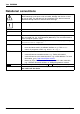
Your ESPRIMO Notational conventions Pay particular attention to text marked with this symbol. Failure to observe these warnings could pose a risk to health, damage the device or lead to loss of data. The warranty will be invalidated if the device becomes defective through failure to observe these warnings. Indicates important information for the proper use of the device.
Important notes Important notes Notes Importantnotes In this chapter you will find information regarding safety which it is essential to take note of when working with your device. Safety information Note Safetyinformation Please note the information provided in the "Safety/regulations" manual and in the following safety notes.
Important notes Cleaning the device System unit,see Device Retransportation Transportation Device, Turn off all power and equipment switches and disconnect the power plug from the mains outlet. Do not clean any interior parts yourself, leave this job to a service technician. Do not use any cleaning agents that contain abrasives or may corrode plastic (alcohol, thinner or acetone). Never clean the device with water! Water entering into the device could present a serious risk to users (e.g. electric shock).
Important notes CE marking Lowvoltagedirective Electromagneticcompatibility Notes CEmarking The shipped version of this device complies with the requirements of European Union directives 2004/108/EC "Electromagnetic compatibility", 2006/95/EC "Low voltage directive" and 2009/125/EC "Ecodesign".
Important notes FCC Compliance Statement If the device complies with the FCC regulations, the FCC sign can be found on the type rating plate. FCC Class B Compliance Statement DOC (INDUSTRY CANADA) NOTICES Notice to Users of Radios and Television : This class B digital apparatus complies with Canadian ICES-003. The following statement applies to the products covered in this manual, unless otherwise specified herein. The statement for other products will appear in the accompanying documentation.
Getting started Getting started Gettingstarted Please observe the safety information in the "Important notes", Page 7 chapter. Unpacking and checking the delivery It is recommended not to throw away the original packaging material! It may be required for reshipment at some later date. Packaging, Contentsofdelivery Packaging ► ► ► ► Unpack all the individual parts. Check the contents of the package for any visible damage caused during transport.
Getting started Setting up the device Device Ergonomic Workstation When installing your device, please read the recommendations and safety notes in the "Safety/regulations" manual. We recommend that you place your device on a surface which is not slippery. In view of the many different finishes and varnishes used on furniture, it is possible that the rubber feet will mark the surface they stand on. Depending on the location of your device, bothersome vibrations and noises may occur.
Getting started Connecting external devices Read the documentation on the external device before connecting it. With the exception of USB devices, always remove all power plugs before connecting external devices! Do not connect or disconnect cables during a thunderstorm. Always take hold of the actual plug. Never unplug a cable by pulling the cable itself. Connect and disconnect the cables in the order described below. Connecting the cables ► Turn off all power and equipment switches.
Getting started Ports on the device Device Externaldevices Interfaces The ports available on your device depend on the selected device configuration level. The ports are located on the front and back of the device. The ports available on your device depend on the configuration level you have selected. The standard ports are marked with the symbols shown below (or similar). Detailed information on the location of the ports is provided in the manual for the mainboard.
Getting started Connecting a monitor ► Follow the instructions contained in the monitor manual to prepare the monitor for operation (e.g. connecting cables). ► Connect the data cable of the monitor into the monitor port of your device. Monitor The optional monitor power cable may only be connected to the monitor socket of the device if the monitor current consumption is less than 1 A with 240 V or 2 A with 100 V.
Getting started Connecting the keyboard You can connect a USB keyboard or a PS/2 keyboard to your device. Connecting, Keyboard, Connecting a USB keyboard Use the supplied keyboard cable only. Connecting, USBport, ► Plug the rectangular connector of the keyboard cable into the rectangular socket on the underside or on the rear of the keyboard. ► Insert the flat rectangular USB plug of the keyboard cable into one of the device’s USB ports.
Getting started Connecting external devices to the USB ports Devices, Externaldevices, USBport, USBdevices, You can connect a wide range of external devices to the USB ports (e.g. printer, scanner, modem or keyboard). USB devices are hot-pluggable. This means you can connect and disconnect USB cables while your device is switched on. Additional information can be found in the documentation for the USB devices. ► Connect the data cable to the external device.
Getting started Switching on monitor and device In order to avoid overheating, do not cover the ventilation areas of the monitor or the device. Depending on the version, the device may be equipped with a main power switch on the back of the device in addition to the ON/OFF button on the front. ► Switch the monitor on (see the operating manual for the monitor). ► Switch the device on. To do this, follow the instructions below.
Operation Operation Switch the device on ► If necessary, switch the monitor on (see the operating manual for the monitor). ► Switch on the device using the main power switch located on the rear of the device (if present). ► Press the ON/OFF switch on the front of the device. The power indicator glows and the device starts. Monitor, Device, Switching off the device ► Shut down the operating system in a defined manner. In Windows: via the Start menu and the Turn Off Computer function.
Operation Indicators on the device Device Indicators, The indicators are on the front of the casing. Which indicators are available on your device depends on the configuration level you have selected. 1 2 3 1 = Drive indicator, e.g. DVD 2 = Power-on indicator No. Indicator 1 Drive indicator 2 Power-on indicator 3 = Hard disk indicator Description The indicator lights up when the CD-ROM or DVD drive in the device is accessed. Never under any circumstances remove the CD/DVD while the indicator is lit.
Operation Keyboard Alphanumeric Keyboard, Keyboard Cursor Function Keys, Numeric keys keypad keys keypad The illustrated keyboard is an example and may differ from the model you use. 1 2 3 1 = Function keys 2 = On/off switch (optional) 3 = Alphanumeric keypad 4 5 4 = Cursor keys 5 = Numeric keypad (calculator keypad) Important keys and keyboard shortcuts Keyboardshortcuts Keys The description of the following keys and keyboard shortcuts applies to Microsoft operating systems.
Operation Key / key combination Description Windows key (device-dependent: variant 1) Keys, calls up the Windows Start menu. Keys, Menu key (device-dependent: variant 1) calls up the menu for the marked item (Windows). Keys Windows key (device-dependent: variant 2) Switches between the start screen and the last used application. Keys Menu key (device-dependent: variant 2) Opens the menu for the active application. Keys, Shift key enables upper-case letters and the upper key symbols to be displayed.
Operation Property and data protection Property protection Securitymeasures Dataprotection Software functions and mechanical locking offer a broad range of functions for protecting your device and your personal data from unauthorised access. You can also combine these functions.
Operation BIOS setup security functions BIOS Setup, Securityfunctions, The Security menu in BIOS Setup offers you various options for protecting your personal data against unauthorized access, e.g.
Troubleshooting and tips Troubleshooting and tips Refer to the safety notes in the "Safety/regulations" manual and in the "Getting started", Page 11 chapter when connecting or disconnecting cables.
Troubleshooting and tips The device cannot be switched off with the ON/OFF switch Cause Remedy System crash ► Keep the on/off switch pressed for at least 4 seconds until the machine switches off. Caution: This can lead to a loss of data! This procedure does not allow the operating system to shut down in an orderly way. The next time the system is started there may well be error messages.
Troubleshooting and tips No mouse pointer displayed on the screen Cause The mouse is not correctly connected. The mouse controller is not enabled. Remedy ► Shut down the operating system properly. ► Switch the device off. ► Check that the mouse cable is properly connected to the system unit. If you use an adapter or extension lead with the mouse cable, check the connections. ► Switch the device on. ► Check in the BIOS-Setup whether the mouse controller is enabled.
Troubleshooting and tips Installing new software When installing programs or drivers, important files may be overwritten and modified. To be able to access the original data in the event of any problems following installation, you should backup your hard disk prior to installation. Restoring hard disk contents Should you need to restore your hard disk, the instructions are provided on the case of the "Recovery DVD" (delivered with your system).
System expansions System expansions System expansion Device, Upgrades, Servicing Components Repairs to the device must only be performed by qualified technicians. Incorrect repairs may greatly endanger the user (electric shock, fire risk) and will invalidate your warranty. After consulting the Hotline/Help Desk, you may remove and install the components described in this manual yourself.
System expansions Information about boards Take care with the locking mechanisms (catches and centring pins) when you are replacing boards or components on boards. Note that some components on the mainboard may be very hot if the device was in use shortly before the casing was removed. To prevent damage to the board or the components and conductors on it, please take care when you insert or remove boards. Make sure expansion boards are inserted straightly.
System expansions Opening the casing Device, Casing, ► Switch the device off. The device must not be in power-saving mode. Please observe the safety information in "Important notes", Page 7. Disconnect the mains plug from the mains outlet. Only insert the power plug after you have closed the casing. ► Remove any connected wires which are in the way. ► Lay the device on its side in the manner shown below. 1 2 1 1 ► Remove the casing screws (1).
System expansions Closing the casing ► Insert the side part in the guide rail on the lower part of the casing. Device, Casing, 1 2 2 ► Slide the side cover onto the casing in the direction of the arrow (1). ► Tighten the casing screws (2). ► Reconnect the cables that you disconnected before.
System expansions Installing and removing the accessible 51/4 inch drive Removing an accessible drive ► Open the casing (see "Opening the casing", Page 31). ► Disconnect the cables connected to the drive. Accessible drive, Drive, 1 1 2 ► Loosen the screws (1). ► Working from behind, slide the drive a short distance out of the bay in the direction of the arrow (2). The drive now protrudes slightly out of the casing. ► Pull the drive out of the casing (2).
System expansions 1 ► Break out the pre-stamped metal cover on the drive bay opening with a screwdriver (1). ► Secure the front panel on the casing again. 2 2 1 ► ► ► ► ► 34 Slide the drive into the casing (1). Make sure that the screw holes are aligned. Fasten the drive into place with the screws (2). Plug the data and the power supply connectors into the drive. Make sure the polarity is correct. If there is an accessible drive, please install it again.
System expansions Installing and removing an accessible 31/2 inch drive Installing an accessible drive ► Open the casing (see "Opening the casing", Page 31). ► If there is an accessible 51/4" drive, remove the drive (see "Removing an accessible drive", Page 33). ► Remove the front panel from the casing. ► From the inside, press the plastic drive cover out of the front panel. Diskettedrive, 1 ► Break out the pre-stamped metal cover on the drive bay opening with a screwdriver (1).
System expansions ► If there is an accessible 51/4" drive, reinstall the drive. ► Close the casing (see "Closing the casing", Page 32). Removing an accessible drive ► Open the casing (see "Opening the casing", Page 31). ► Disconnect all cables connected to the drive (data cable, power supply cable). 1 1 2 ► Remove the screws (1). ► Slide the drive out of the bay from behind, in the direction of the arrow (2). ► Close the casing (see "Closing the casing", Page 32).
System expansions Installing and removing the hard disk drive Harddiskdrive, Removing a hard disk drive ► Open the casing (see "Opening the casing", Page 31). ► Remove all connected cables (data cable, power supply) from the drive. Harddisk drive, 11 1 1 2 ► Undo the screws (1) and gently press against the hard disk drive from underneath. ► Pull the drive backwards a short way out of the bay in the direction of the arrow (2). The drive now protrudes slightly out of the bay.
System expansions Installing a hard disk drive ► Open the casing (see "Opening the casing", Page 31). ► Take the new hard disk drive out of its packaging. Harddisk drive, 22 2 2 1 ► Slide the hard disk drive into the casing (1). Make sure that the screw holes are aligned. ► Press gently against the hard disk drive from below and secure it with the screws (2). ► Connect the cables (data cable, power supply) to the drive. Check that the polarity is correct and do not use any force.
System expansions Installing and removing a board You can install additional modules in order to increase the performance of your machine. The number, position and arrangement of the board slots on the mainboard can be found in the manual for the mainboard. Boards may already be installed on shipment. Board, Board installing ► Open the casing (see "Opening the casing", Page 31). Board, 2 1 ► Remove the screw (1) from the cover plate (1).
System expansions Do not throw away the slot cover. For cooling, protection against fire and in order to comply with EMC regulations, you must refit the slot cover if you remove the board. 2 1 ► ► ► ► ► Push the board into the slot (1). Tighten the screw on the slot cover (2). Secure the cover plate on the casing again. If necessary, connect the cables to the board. Close the casing (see "Closing the casing", Page 32).
System expansions Board removing ► Open the casing (see "Opening the casing", Page 31). ► Remove the cover plate (see "Board installing", Page 39). ► Disconnect the cables connected to the board. Board, 1 2 ► Remove the screw on the board (1). ► Pull the board out of the slot in the direction of the arrow (2). ► Place the board in suitable packaging.
System expansions For cooling, protection against fire, and in order to comply with EMC (electromagnetic compatibility) regulations, you must refit the slot cover. 2 1 ► ► ► ► Slide the slot cover into the slot (1). Secure the slot cover in position with the screw (2). Secure the cover plate on the casing again. Close the casing (see "Closing the casing", Page 32). If you have installed or removed a PCI board, please check the relevant PCI slot settings in the BIOS Setup.
System expansions Replacing the lithium battery In order to permanently save the system information, a lithium battery is installed to provide the CMOS-memory with a current. A corresponding error message notifies the user when the charge is too low or the battery is empty. The lithium battery must then be replaced. Incorrect replacement of the lithium battery may lead to a risk of explosion! The lithium battery may be replaced only with an identical battery or with a type recommended by the manufacturer.
Technical specification Technical specification Electrical data Safety standards complied with: Protection class: Rated voltage range Rated voltage range Rated frequency Rated frequency Rated current Max. rated current Dimensions Width/depth/height: ESPRIMO P410 / P420 / P520 / ESPRIMO P400 / PH300 PH310 S26113-E582-V50 S26113-E611-V50 S26113–E611–V70 IEC 60950-1, EN 60950-1, UL 60950CSA 22.2 No.60950-1 I 100 V – 240 V 50 Hz – 60 Hz 3.0 A – 1.5 A 3.5 A – 1.5 A 175 mm x 417 mm x 354 mm / 6.88 inch x 16.
Index Index A Access permission, SmartCard Accessible drive, removing 33 Alphanumeric keypad 21 Anti-theft protection 23 Audio input 14 Audio output 14 24 B Battery 43 BIOS Setup 22 BIOS Setup, configuration 22 security functions 24 settings 22 system settings 22 Board, installing 39 removing 39, 41 Button, ON/OFF switch 21 C Cable, connecting 13 disconnecting 13 Casing, closing 32 Lead-sealing 23 opening 31 CE marking 9 Chain 23 Components installing/removing 29 Connecting a PS/2 keyboard Connecting, ke
Index I Important notes 7 Indicators, device 20 Installing, software 17–18 switching on for the first time Interfaces 14 K Kensington Lock 23 Keyboard 21 Keyboard port 14 keyboard shortcuts 22 Keyboard shortcuts 21 Keyboard, alphanumeric keypad connecting 16 cursor keys 21 function keys 21 numeric keypad 21 port 16 Keys 21 Ctrl 22 Ctrl+Alt+Del 22 Menu key 22 Keys, Alt Gr 22 Control 22 Ctrl key 22 cursor keys 21 Enter 21 Enter key 21 menu key 22 Num Lock 22 Return 21 shift 22 shift key 22 Start key 22 L LAN
Index S Safety information 7 Security functions, BIOS Setup 24 SmartCard 24 Security measures 23 Serial interface 16 Serial interface, connecting devices 16 settings 16 Serial port 14 Servicing 29 Setup, see BIOS Setup 22 Software, installing 17–18 System expansion 29 System settings, BIOS Setup 22 System unit, see Device 8 T Transportation Fujitsu U Universal Serial Bus 14 Upgrades Mainboard 42 Upgrades, device 29 USB devices, connecting 17 USB port 15–16 USB port, connecting devices 17 connecting keybo