
AGU9RLF Installation Manual

En-10
1
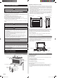
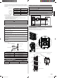
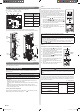
11.5. Connecting cable to control board connector
(1) Connect the cable the circuit board and hang on the hooks.
PCB
CN 6
CN 21
(EX. OUT2)
CN 14
(EX. IN1)
CN 20
(EX. OUT1)
Option type
Connector
No.
Wired remote controller
Simple remote controller
CN 6
External input
CN 14
(EX. IN1)
External output
(operation status)
CN 20
(EX. OUT1)
External output
(error status)
CN 21
(EX. OUT2)
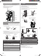
(2) Install the control cover.
(3) Use cable clamper and screw to fasten the cable of wired remote controller.
(4)
Fix the cable tie holder with the screw and bind the cable of external kit with the cable tie.
Earth
(Ground)
wire
Screw
Hook
Cable
Cable tie
Cable tie holder
Cable
clump
Screw
Screw
]1
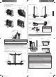
11.6. Side panel L and control cover installation
Install Side panel L and control cover by the reverse procedures as stated in “11.4. Side
panel L and control cover removal”.
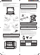
12. FUNCTION SETTING
Perform the “FUNCTION SETTING” according to the installation conditions using the
remote controller.
CAUTION
Confi rm whether the wiring work for Outdoor unit or Branch box has been fi nished.
Confi rm that the cover for the electrical enclosure on the outdoor unit is in place.
• This procedure changes to the function settings used to control the indoor unit
according to the installation conditions. Incorrect settings can cause the indoor unit to
malfunction.
• After the power is turned on, perform the “FUNCTION SETTING” according to the
installation conditions using the remote controller.
• The settings may be selected between the following two: Function Number or Setting
Value.
• Settings will not be changed if invalid numbers or setting values are selected.
• Refer to the installation manual enclosed with the remote controller when the wired
remote controller (option) is used.
Entering the Function Setting Mode
While pressing the POWERFUL button and SET TEMP. ( ) simultaneously, press the
RESET button to enter the function setting mode.
STEP 1
Selecting the Remote Controller Custom Code
Use the following steps to select the custom code of the remote con-
troller. (Note that the air conditioner cannot receive a custom code if
the air conditioner has not been set for the custom code.)
The custom codes that are set through this process are applicable only
to the signals in the FUNCTION SETTING. For details on how to set
the custom codes through the normal process, refer to Remote control-
ler custom code.
(1) Press SET TEMP. ( / ) button to change the custom
code between
. Match the code on the dis-
play to the air conditioner custom code. (initially set to
)
(If the custom code does not need to be selected, press the
MIN. HEAT button and proceed to STEP 2.)
(2)
Press the MODE button and check that the indoor unit can
receive signals at the displayed custom code.
(3) Press the MIN. HEAT button to accept the custom code,
and proceed to STEP 2.
The air conditioner custom code is set to A prior to shipment.
Contact your retailer to change the custom code.
The remote controller resets to custom code A when the batteries in the remote
controller are replaced. If you use a custom code other than custom code A, reset the
custom code after replacing the batteries.
If you do not know the air conditioner custom code setting, try each of the custom
codes (
) until you fi nd the code which operates the air conditioner.
STEP 2
Selecting the Function Number and Setting Value
(1) Press the SET TEMP. ( / ) buttons to select the
function number. (Press the MIN. HEAT button to
switch between the left and right digits.)
(2) Press the
POWERFUL
button to proceed to setting
value. (Press the
POWERFUL
button again to return
to the function number selection.)
(3) Press the SET TEMP. (
/ ) buttons to select the
setting value. (Press the MIN. HEAT button to switch
between the left and right digits.)
(4) Press the MODE button, and START/STOP button, in
the order listed to confi rm the settings.
(5) Press the RESET button to cancel the function set-
ting mode.
(6) After completing the FUNCTION SETTING, be sure
to turn off the power and turn it on again.
CAUTION
After turning off the power, wait 10 seconds or more before turning on it again.
The Function Setting does not become active unless the power is turned off then on
again.
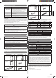
Filter Sign
The indoor unit has a sign to inform the user that it is time to clean the fi lter. Select the
time setting for the fi lter sign display interval in the table below according to the amount
of dust or debris in the room. If you do not wish the fi lter sign to be displayed, select the
setting value for “No indication”.
(♦... Factory setting)
Setting Description Function Number Setting Value
Standard (400 hours)
11
00
Long interval (1,000 hours) 01
Short interval (200 hours) 02
♦ No indication 03
Function Number
Setting
Value
9378533059_IM.indb 109378533059_IM.indb 10 9/20/2013 11:26:15 AM9/20/2013 11:26:15 AM