
AGU9RLF Installation Manual


En-12
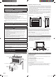
13. CUSTOMER GUIDANCE
Explain the following to the customer in accordance with the operating manual:
(1) Starting and stopping method, operation switching, temperature adjustment, timer, air
fl ow switching, and other remote controller operations.
(2) Air fi lter removal and cleaning, and how to use the air louvers.
(3) Give the operating manual to the customer.
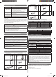
14. ERROR CODES
If you use a wireless remote controller, the lamp on the photo detector unit will output
error codes by way of blinking patterns. If you use a wired remote controller, error codes
will appear on the remote control display. See the lamp blinking patterns and error codes
in the table. An error display is displayed only during operation.
Error display
Wired
remote
controller
Error code
Description
OPERATION
lamp
(green)
TIMER
lamp
(orange)
ECONOMY
lamp
(green)
(1) (1)
Serial communication error
(1) (2)
Wired remote controller
communication error
(1) (5)
Check run unfi nished
(2) (1)
Unit number or Refrigerant circuit
address setting error
[Simultaneous Multi]
(2) (2)
Indoor unit capacity error
(2) (3)
Combination error
(2) (4)
Connection unit number •
error (indoor slave unit)
[Simultaneous Multi]
Connection unit number error •
(indoor unit or branch unit)
[Flexible Multi]
(2) (7)
Master unit, slave unit set-up error
[Simultaneous Multi]
(3) (2)
Indoor unit PCB model
information error
(3) (5)
Manual auto switch error
(4) (1)
Inlet air temp. sensor error
(4) (2)
Indoor unit Heat Ex. Middle temp.
sensor error
(5) (1)
Indoor unit fan motor error
(5) (3)
Drain pump error
(5) (7)
Damper error
(5) (15)
Indoor unit error
(6) (2)
Outdoor unit main PCB model
information error or
communication error
(6) (3)
Inverter error
(6) (4)
Active fi lter error, PFC circuit error
(6) (5)
Trip terminal L error
(6) (10)
Display PCB microcomputers
communication error
(7) (1)
Discharge temp. sensor error
(7) (2)
Compressor temp. sensor error
(7) (3)
Outdoor unit Heat Ex. liquid temp.
sensor error
(7) (4)
Outdoor temp. sensor error
(7) (5)
Suction Gas temp. sensor error
(7) (6)
2-way valve temp. sensor error•
3-way valve temp. sensor error•
(7) (7)
Heat sink temp. sensor error
(8) (2)
Sub-cool Heat Ex. gas inlet •
temp. sensor error
Sub-cool Heat Ex. gas outlet •
temp. sensor error
(8) (3)
Liquid pipe temp. sensor error
(8) (4)
Current sensor error
(8) (6)
Discharge pressure sensor error•
Suction pressure sensor error•
High pressure switch error•
(9) (4)
Trip detection
(9) (5)
Compressor rotor position
detection error (permanent stop)
(9) (7)
Outdoor unit fan motor error
(9) (9)
4-way valve error
(10) (1)
Discharge temp. error
(10) (3)
Compressor temp. error
(10) (4)
High pressure error
(10) (5)
Low pressure error
(13) (2)
Branch boxes error
[Flexible Multi]
Display mode
: 0.5s ON / 0.5s OFF
: 0.1s ON / 0.1s OFF
( ) : Number of fl ashing
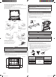
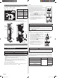
[Troubleshooting with the indoor unit display]
TIMER
TIMER lamp
(orange)
OPERATION
lamp (green)
ECONOMY
lamp (green)
OPERATION ECONOMY
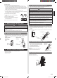
[Troubleshooting with the Wired Remote Controller Display (Option)]
If an error occurs, the following display will be shown. (“Er” will appear in the set room
temperature display.)
Error code
9378533059_IM.indb 129378533059_IM.indb 12 9/20/2013 11:26:18 AM9/20/2013 11:26:18 AM