
AGU9RLF Installation Manual

En-3
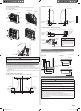
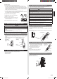
2.2. Special tools for R410A
Tool name Contents of change
Gauge manifold
Pressure is high and cannot be measured with a conven-
tional (R22) gauge. To prevent erroneous mixing of other
refrigerants, the diameter of each port has been changed.
It is recommended the gauge with seals -0.1 to 5.3 MPa
(30 inHg to 768 psi) for high pressure.
-0.1 to 3.8 MPa (30 inHg to 551 psi) for low pressure.
Charge hose
To increase pressure resistance, the hose material and base
size were changed.
Vacuum pump
A conventional vacuum pump can be used by installing a
vacuum pump adapter.
Gas leakage detector Special gas leakage detector for HFC refrigerant R410A.
Copper pipes
It is necessary to use seamless copper pipes and it is desirable that the amount of residual
oil is less than 40 mg/10 m (0.004 oz/100 ft.). Do not use copper pipes having a collapsed,
deformed or discolored portion (especially on the interior surface). Otherwise, the expansion
value or capillary tube may become blocked with contaminants.
As an air conditioner using R410A incurs pressure higher than when using R22, it is nec-
essary to choose adequate materials.
WARNING
Do not use the existing (for R22) piping and fl are nuts.
If the existing materials are used, the pressure inside the refrigerant cycle will rise and
cause failure, injury, etc. (Use the special R410A materials.)
When installing and relocating the air conditioner, do not mix gases other than the
specifi ed refrigerant (R410A) to enter the refrigerant cycle.
If air or other gas enters the refrigerant cycle, the pressure inside the cycle will rise to
an abnormally high value and cause failure, injury, etc.
2.3. For authorized service personnel only.
WARNING
For the air conditioner to operate satisfactorily, install it as outlined in this installation
manual.
Connect the indoor unit and outdoor unit or branch box with the air conditioner piping
and cables available from your local distributor. This installation manual describes the
correct connections using the installation set available from your local distributor.
Do not turn on the power until all installation work is complete.
CAUTION
This installation manual describes how to install the indoor unit only.
To install the outdoor unit or branch box, refer to the installation manual included with
the outdoor unit or branch box.
• Be careful not to scratch the air conditioner when handling it.
• After installation, explain correct operation to the customer, using the operating manual.
1
]
1
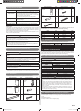
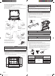
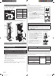
2.4. Accessories
The following installation accessories are supplied. Use them as required.
Name and Shape Q’ty Name and Shape Q’ty
Operating Manual
1
Remote
controller
holder
1
Installation Manual
(This manual)
1
Cloth tape
1
Wall hook bracket
1
Tapping screw
(M4 × 25 mm)
9
Name and Shape Q’ty Name and Shape Q’ty
Remote
controller
1
Tapping screw
(M3 × 12 mm)
2
Battery
2
Air cleaning filter
2
Cable tie
1
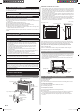
The following items are necessary to install this air conditioner. (The items are not
included with the air conditioner and must be purchased separately.)
Name Q’ty Name Q’ty
Connection pipe assembly 1 Wall cap 1
Connection cable (4-conductor) 1 Saddle 1 set
Wall pipe 1 Drain hose 1
Decorative tape 1 Tapping screws 1 set
Vinyl tape 1 Sealant 1
1
2.5. Optional parts
Refer to each installation manual for the method of installing optional parts.
Parts name Model No. Application
Wired Remote Controller UTY-RNNUM For air conditioner operation
Simple Remote Controller UTY-RSNUM For air conditioner operation
External connect kit UTY-XWZXZ5 For control input/output port
3. GENERAL SPECIFICATION
This INSTALLATION MANUAL briefl y outlines where and how to install the air conditioning
system. Please read over the entire set of instructions for the indoor and outdoor units and
make sure all accessory parts listed are with the system before beginning.
]1
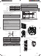
3.1. Type of copper pipe and insulation material
CAUTION
Refer to the installation manual for the outdoor unit for description of allowable pipe
length and height difference.
MODEL
Diameter
Liquid pipe Gas pipe
9,000 Btu/h model 6.35 mm (1/4 in.) 9.52 mm (3/8 in.)
12,000 Btu/h model 6.35 mm (1/4 in.) 9.52 mm (3/8 in.)
15,000 Btu/h model 6.35 mm (1/4 in.) 12.70 mm (1/2 in.)
Pipe length
MAX. MIN.
20 m (65 ft.) 3 m (10 ft.)
CAUTION
Install heat insulation around both the gas and liquid pipes. Failure to do so may
cause water leaks.
Use heat insulation with heat resistance above 120 °C (248 °F). Reverse cycle model
only.
In addition, if the humidity level at the installation location of the refrigerant piping is
expected to exceed 70%, install heat insulation around the refrigerant piping. If the
expected humidity level is 70-80%, use heat insulation that is 15 mm (19/32 in.) or
thicker and if the expected humidity exceeds 80%, use heat insulation that is 20 mm
(25/32 in.) or thicker.
If heat insulation is used that is not as thick as specifi ed, condensation may form on
the surface of the insulation. In addition, use heat insulation with heat conductivity of
0.045 W/(m•K) or less (at [20 °C (68 °F)]).
]1
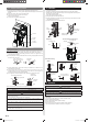
3.2. Additional materials required for installation
A. Refrigeration (armored) tape
B. Insulated staples or clamps for connecting wire (See your local electrical codes.)
C. Putty
D. Refrigeration lubricant
E. Clamps or saddles to secure refrigerant piping
]
1
9378533059_IM.indb 39378533059_IM.indb 3 9/20/2013 11:26:08 AM9/20/2013 11:26:08 AM