
AGU9RLF Installation Manual

En-4
4. ELECTRICAL REQUIREMENT
The indoor unit is powered from the outdoor unit or branch box. Do not power indoor unit
from separate power source.
WARNING
Refer to local codes for acceptable cable type.
5. SELECTING THE MOUNTING POSITION
Decide the mounting position with the customer as follows:
(1) Install the indoor unit level on a strong wall which is not subject to vibration.
(2) The inlet and outlet ports should not be obstructed: the air should be able to blow all
over the room.
(3) Install the unit a dedicated electrical branch circuit.
(4) Do not install the unit where it will be exposed to direct sunlight.
(5) Install the unit where connection to the outdoor unit or branch box is easy.
(6) Install the unit where the drain pipe can be easily installed.
(7) Take servicing, etc. into consideration and leave the spaces shown in the figure. Also
install the unit where the filter can be removed.
Correct initial installation location is important because it is diffi cult to move unit after it is
installed.
WARNING
Select installation locations that can properly support the weight of the indoor. Install
the units securely so that they do not topple or fall.
CAUTION
Do not install the unit in the following areas:
• Area with high salt content, such as at the seaside.
It will deteriorate metal parts, causing the parts to fail or the unit to leak water.
• Area fi lled with mineral oil or containing a large amount of splashed oil or steam,
such as a kitchen.
It will deteriorate plastic parts, causing the parts to fail or the unit to leak water.
• Area that generates substances that adversely affect the equipment, such as
sulfuric gas, chlorine gas, acid, or alkali.
It will cause the copper pipes and brazed joints to corrode, which can cause
refrigerant leakage.
• Area that can cause combustible gas to leak, contains suspended carbon fi bers or
fl ammable dust, or volatile infl ammables such as paint thinner or gasoline.
If gas leaks and settles around the unit, it can cause a fi re.
• Area where animals may urinate on the unit or ammonia may be generated.
Do not use the unit for special purposes, such as storing food, raising animals, growing
plants, or preserving precision devices or art objects.
It can degrade the quality of the preserved or stored objects.
Do not install where there is the danger of combustible gas leakage.
Do not install the unit near a source of heat, steam, or fl ammable gas.
Install the unit where drainage does not cause any trouble.
Install the indoor unit, outdoor unit, branch box, power supply cable, transmission
cable, and remote control cable at least 1 m (39 in.) away from a television or radio
receivers. The purpose of this is to prevent TV reception interference or radio noise.
(Even if they are installed more than 1 m (39 in.) apart, you could still receive noise
under some signal conditions.)
If children under 10 years old may approach the unit, take preventive measures so that
they cannot reach the unit.
6. INSTALLATION WORK
]1
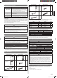
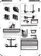
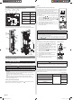
6.1. Installation dimensions
(Wall cap)
50 (1-15/16) or over
80 (3-2/16) or over
100 (3-15/16) or over
80 (3-2/16) or over
Unit: mm (in.)
150 (5-14/16) or
below from the fl oor
Remote controller
holder
Tapping screw
(small)
Remote
controller
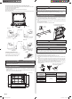
EMBEDDING THE INDOOR UNIT IN A WALL
• When installing a grating, use a grating with narrow upper and lower horizontal bars
so that the airfl ow from the upper and lower air outlets does not contact the bars. If the
horizontal bars will block the lower air outlet, use a stand, etc., to adjust the height of
the indoor unit. If the upper or lower air outlet is blocked, the air conditioner will not be
able to cool or warm the room well.
• Do not block the receiver with the grating. Otherwise, the grating will interfere with the
remote controller signal and signifi cantly reduce the distance and area (angle) from
which the signals can be received.
• Use a grating with vertical bars, etc., that has at least 75% open area. If the grating has
horizontal bars or if the open area is less than 75%, performance could be reduced.
• When the indoor unit is embedded in a wall (built-in), the time it takes for the room
temperature to reach the set temperature will increase.
20 (13/16)~
30 (1-3/16)
Upper air outlet
80 (3-2/16) or more
80 (3-2/16) or more
Indoor
unit
Unit: mm (in.)
Lower air outlet
100 (3-15/16) or more
Grating
When embedding the indoor unit in a wall, restrict the movement of the horizontal vane
for the upper air outlet so that it only operates horizontally. If this setting is not performed,
heat will build up in the wall and the room will not be cooled or warmed properly.
Please explain the vane setting of direction only horizontally to the customer.
HOW TO SETTING VANE
Perform the “FUNCTION SETTING” according to the installation condition using the
remote controller. Refer to “12. FUNCTION SETTING”.
]1
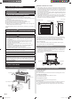
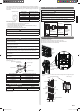
6.2. Indoor unit piping direction
The piping can be connected in the 6 directions indicated by (1), (2), (3), (4), (5) and (6)
in the fi gure. When the piping is connected in direction (2) or (5), cut along the piping
groove in the side of the base with a hacksaw.
When connecting the piping in direction (3), (6) cut a notch in the thin wall at the front
bottom of the base.
(1) Right rear
outlet
(2) Right outlet
(3) Right bottom
outlet
(4) Left rear
outlet
(5) Left outlet
(Rear)
(6) Left bottom
outlet
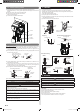
6.3. Side panel L, R removal and installation
The intake grille removal
(1) Open the intake grille.
(2) Remove the rope.
(3) Lay down the intake grille, until the axle at the bottom of the intake grille is removed.
The intake grille installation
(1) The fi xing axle of the intake grille is installed on the Panel.
(2) Lift the intake grille upward.
The side panel L, R removal
(1) Remove intake grille (Reference the intake grille removal.)
(2) Remove 4 screws.
(3) The middle fi nger is hung on the lower part as shown in the fi gure, and it pulls to the
front, pushing [►] mark, and bottom hooks (2 position) is removed from Base.
(4) The side panel is pulled to the front, raising the upper surface, and a side panel is
removed.
9378533059_IM.indb 49378533059_IM.indb 4 9/20/2013 11:26:08 AM9/20/2013 11:26:08 AM