
AGU9RLF Installation Manual
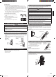

En-6
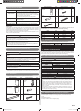
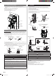
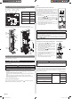
The drain hose can be connected at either side of the indoor unit.
The unit has been shipped with the drain hose connected at left (viewed from the back of
the unit) and the drain cap applied at right.
(1) Remove the both side panels.
(2) Remove the screw and remove the drain holder from drain pan.
(3) Pull out the drain cap.
(4)
Connect the drain hose to the right, attach the screw and insert the drain cap to the left.
DRAIN
HOSE
DRAIN CAP
Drain pan
DRAIN HOSE
Drain holder
Screw
Drain pan
DRAIN CAP
Drain holder
DRAIN HOSE
Screw
DRAIN CAP
Installation method of Drain cap
Use a hexagonal wrench (4 mm (3/16 in.) at
opposite side) to insert the drain cap, till the
drain cap contacts the tip of drain cook.
No gap
Drain cock
Drain capHexagon
wrench
CAUTION
Insert the drain hose and drain cap into the drain port, making sure that it comes
in contact with the back of the drain port, and then mount it. If the drain hose is not
connected properly, leaking will occur.
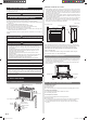
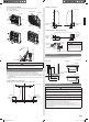
6.7. Indoor unit installation
• Use the included and fasten the indoor unit at 4 locations (→) each at top and the
middle of the unit.
• When the unit is set to the wall, use the wall hook bracket and hook the top of the
indoor unit on the indoor unit wall hook bracket.
Unit: mm (in.)
423 (16-10/16)124 (4-14/16)
703 (27-11/16)
124 (4-14/16) 438 (17-4/16)
WARNING
Fix the indoor unit with 4 screws surely. If improperly installed, might cause to injury
due to the toppling or falling.
Install the indoor unit at the place that has adequate strength. Install the indoor unit so
that the installed unit can withstand the weight of adult body weight.
If improperly installed, might cause accidental injury due to the toppling or falling.
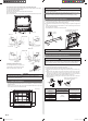
6.8. Installing the wall hook bracket
(1) Install the wall hook bracket so that it is correctly positioned horizontally and vertically.
If the wall hook bracket is tilted, water will drip to the fl oor.
(2) Install the wall hook bracket so that it is strong enough to support the weight of the
unit.
• Fasten the wall hook bracket to the wall with 5 or more screws through the holes near
the outer edge of the bracket.
• Check that there is no rattle at the wall hook bracket.
Weight
Leveling
method
Hook the indoor unit to the wall
hook bracket (2 positions)
CAUTION
Install the wall hook bracket level, both horizontally and vertically.
6.9. Flare connection (Pipe connection)
WARNING
Tighten the flare nuts with a torque wrench using the specified tightening method.
Otherwise, the fl are nuts could break after a prolonged period, causing refrigerant to
leak and generate hazardous gas if the refrigerant comes into contact with a fl ame.
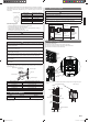
6.9.1. Flaring
Use special pipe cutter and fl are tool exclusive for R410A.
(1) Cut the connection pipe to the necessary length with a pipe cutter.
(2) Hold the pipe downward so that cuttings will not enter the pipe and remove any
burrs.
(3) Insert the flare nut (always use the flare nut attached to the indoor unit(s) and
outdoor unit or branch box respectively) onto the pipe and perform the flare
processing with a fl are tool. Use the special R410A fl are tool, or the conventional
fl are tool. Leakage of refrigerant may result if other fl are nuts are used.
(4) Protect the pipes by pinching them or with tape to prevent dust, dirt, or water from
entering the pipes.
L
Check if [L] is flared uniformly and
is not cracked or scratched.
Pipe
Die
Pipe outside diameter
[mm (in.)]
Dimension A [mm (in.)]
Dimension B [mm (in.)]
Flare tool for R410A,
clutch type
6.35 (1/4)
0 to 0.5
(0 to 1/32)
9.1 (11/32)
9.52 (3/8)
13.2 (17/32)
12.70 (1/2)
16.6 (21/32)
15.88 (5/8)
19.7 (25/32)
19.05 (3/4)
24.0 (15/16)
9378533059_IM.indb 69378533059_IM.indb 6 9/20/2013 11:26:11 AM9/20/2013 11:26:11 AM