
AGU9RLF Installation Manual

En-7
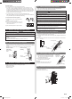
When using conventional fl are tools to fl are R410A pipes, the dimension A should be
approximately 0.5 mm (1/32 in.) more than indicated in the table (for fl aring with R410A
flare tools) to achieve the specified flaring. Use a thickness gauge to measure the
dimension A.
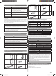
Width across flats
flats
Pipe outside
diameter [mm (in.)]
Width across fl ats of
Flare nut [mm (in.)]
6.35 (1/4)
17 (21/32)
9.52 (3/8)
22 (7/8)
12.70 (1/2)
26 (1-1/32)
15.88 (5/8)
29 (1-5/32)
19.05 (3/4)
36 (1-13/32)
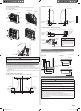
6.9.2. Bending pipes
• If pipes are shaped by hand, be careful not to collapse them.
• Do not bend the pipes in an angle more than 90°.
• When pipes are repeatedly bend or stretched, the material will harden, making it
diffi cult to bend or stretch them any more.
• Do not bend or stretch the pipes more than 3 times.
CAUTION
To prevent breaking of the pipe, avoid sharp bends.
If the pipe is bent repeatedly at the same place, it will break.
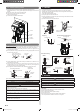
6.9.3. Pipe connection
CAUTION
Be sure to install the pipe against the port on the indoor unit correctly. If the centering
is improper, the fl are nut cannot tighten smoothly. If the fl are nut is forced to turn, the
threads will be damaged.
Do not remove the flare nut from the indoor unit pipe until immediately before
connecting the connection pipe.
Hold the torque wrench at its grip, keeping it in the right angle with the pipe, in order to
tighten the fl are nut correctly.
Tighten the flare nuts with a torque wrench using the specified tightening method.
Otherwise, the fl are nuts could break after a prolonged period, causing refrigerant to
leak and generate hazardous gas if the refrigerant comes into contact with a fl ame.
Connect the piping so that the control box cover can easily be removed for servicing
when necessary.
In order to prevent water from leaking into the control box, make sure that the piping is
well insulated.
When the flare nut is tightened properly by your hand, hold the body side coupling
with a wrench, then tighten with a torque wrench. (See following table for the fl are nut
tightening torques.)
Wrench (fi xed)
Connection pipe
Flare nut
Indoor unit pipe
Tighten with two wrenches.
Torque wrench
Flare nut [mm (in.)] Tightening torque [N·m (kgf·cm)]
6.35 (1/4) dia. 16 to 18 (160 to 180)
9.52 (3/8) dia. 32 to 42 (320 to 420)
12.70 (1/2) dia. 49 to 61 (490 to 610)
15.88 (5/8) dia. 63 to 75 (630 to 750)
19.05 (3/4) dia. 90 to 110 (900 to 1,100)
7. ELECTRICAL WIRING
Cable Cable size Remarks
Connection cable 14AWG UL 1505
3 cable+Earth (Ground),
1φ 208/230 V
Max. Cable Length: Limit voltage drop to less than 2%. Increase cable gauge if voltage
drop is 2% or more.
]1
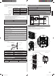
7.1. Wiring system diagram
WARNING
Before connecting the wires, make sure the power supply is OFF.
Every wire must be connected fi rmly.
No wire should be allowed to touch refrigerant tubing, the compressor or any moving
part.
Loose wiring may cause the terminal to overheat or result in unit malfunction. A fi re
hazard may also exist. Therefore, be sure all wiring is tightly connected.
Connect wires to the matching numbers of terminals.
INDOOR UNIT SIDE
Earthing
(Grounding) line
DISCONNECT
SWITCH
(FIELD SUPPLY)
OUTDOOR UNIT
or BRANCH BOX
Connect it to
the specifi ed
terminal.
INDOOR UNIT
TERMINAL
Power line
Control line
]1
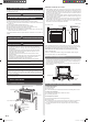
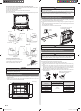
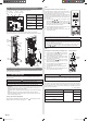
7.2. Indoor unit wiring
(1) Remove the terminal cover.
(2) Remove the cable clamp.
(3) Bend the end of the connection wire as shown in the fi gure.
(4) Connect the end of the connection wire fully into the terminal block.
(5) Fasten the connection wire with a cable clamp.
Cable
clamp
Cable
clamp
Connection
cable
Terminal
cover
• To connect the indoor unit wires to the terminal correctly, refer to the fi gure for proper
length.
14AWG
Earth (Ground) wire
Conduit connector
10 (6/16)
(35 (1-6/16))
(15 (9/16))
65 (2-9/16)
10 (6/16)
Unit: mm (in.)
85 (3-6/16)
9378533059_IM.indb 79378533059_IM.indb 7 9/20/2013 11:26:12 AM9/20/2013 11:26:12 AM