
AGU9RLF Installation Manual

En-8
]1]1
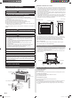
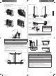
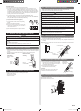
8. FINISHING
(1) Insulate between pipes.
• Overlap the connection pipe heat insulation and indoor unit pipe heat insulation.
• Wrapping the connection pipe with cloth tape over the range within which they fi t into
the rear piping housing section.
• Fasten the pipe bracket with the screw.
(2) Fixing the pipe and conduit with cable ties.
(3) Fill the gap between the outside wall pipe hole and the pipe with sealer so that rain
water and wind cannot blow in.
(4) Fasten the drain hose to the outside wall, etc.
Cloth
tape
Front side of
pipe bracket
Wrap the each pipe
with cloth tape
Pipe
bracket
Screw
Conduit
Left piping
For connection from the left rear
Wall pipe
Connection wire
Drain hose
Connection
pipe
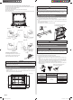
Connection wire
Drain hose
Pipe
Conduit
Pipe
Cable tie
30 mm
(1-3/16 in.)
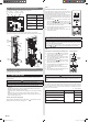
Check the following:
GOOD
PROHIBITED
Accumulated
drain water
No upward
slope
50 mm (1-15/16 in.)
or less from ground
Stopping
downward
No upward
slope
End of drain hose
is immersed in
water.
Drainage
channel
Air
9. TEST RUN
WARNING
Do not turn on the power until all installation work is complete.
CAUTION
When restarting after a long period of disuse in the winter, turn the power switch on at
least 12 hours before starting the unit.
Check items
(1) Is operation of each button on the remote controller normal?
(2) Does each lamp light normally?
(3) Do air fl ow direction louvers operate normally?
(4) Is the drain normal?
(5) Do not have an abnormal noise and vibration during operation?
● Do not operate the air conditioner in test run for a long time.
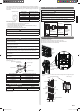
7.3. Conduit mounting method
(1) Fasten the indoor unit wire harness to the conduit holder using the lock nut.
IMPORTANT: Refer to [7.1. Wiring system diagram] about the length of indoor unit wire
harness.
(2) Remove the screws, then remove the cable clamper.
(3) Connect indoor unit wire harness to the terminal.
Refer to the wiring diagram
(4) Use the screws to install the cable clamper.
Lock nut
Conduit
holder
Conduit
connector
]1
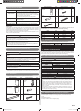
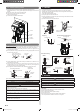
7.4. How to connect wiring to the terminals
Caution when wiring cable
When stripping off the insulation of a lead wire, always use a special tool such as a wire
stripper. If there is no special tool available, carefully strip the insulation with a knife etc.
(1) Use crimp-type terminals with insulating sleeves as shown in the figure below to
connect to the terminal block.
(2) Securely clamp the crimp-type terminals to the wires using an appropriate tool so that
the wires do not come loose.
Strip: 10 mm (6/16 in.)
Sleeve
Crimp-type
terminal
(3) Use the specifi ed wires, connect them securely, and fasten them so that there is no
stress placed on the terminals.
(4) Use an appropriate screwdriver to tighten the terminal screws. Do not use a
screwdriver that is too small, otherwise, the screw heads may be damaged and
prevent the screws from being properly tightened.
(5) Do not tighten the terminal screws too much, otherwise, the screws may break.
Screw with special washer
Screw with
special washer
Crimp-type terminal
Terminal blocks
Crimp-type
terminal
Wire
Wire
(6) See the table below for the terminal screw tightening torques.
Tightening torque [N·m (kgf·cm)]
M4 screw 1.2 to 1.8 (12 to 18)
CAUTION
Match the terminal block numbers and connection cable colors with those of the
outdoor unit or branch box.
Erroneous wiring may cause burning of the electric parts.
Connect the connection cables fi rmly to the terminal block. Imperfect installation may
cause a fi re.
Always fasten the outside covering of the connection cable with the cable clamp. (If
the insulator is chafed, electric discharge may occur.)
Always connect the earth (ground) wire.
Do not use the earth (ground) screw of the indoor unit for the connection other than a
specifi ed outdoor unit or branch box.
9378533059_IM.indb 89378533059_IM.indb 8 9/20/2013 11:26:13 AM9/20/2013 11:26:13 AM