
AGU9RLF Operation Manual

En-5
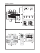
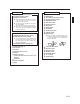
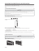
Fig. 1 Indoor Unit
1
Operating Control Panel (Fig. 2)
2
Air Outlet Selection switch
3
MANUAL AUTO button
●
When the MANUAL AUTO button is pressed
in for more than 10 seconds, the forced
cooling operation will start.
●
The forced cooling operation is used at the
time of installation.
Only for authorized service personnel's use.
●
When the forced cooling operation starts by
any chance, press the START/STOP button
to stop the operation.
4
Indicator (Fig. 3)
5
Remote Control Signal Receiver
6
OPERATION Indicator Lamp (green)
7
TIMER Indicator Lamp (orange)
●
If the TIMER indicator lamp flashes when
the timer is operating, it indicates that a fault
has occurred with the timer setting (See
Page 16 Auto Restart).
8
ECONOMY Indicator Lamp (green)
9
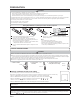
Intake Grille (Fig. 4)
0
Front Panel
A
Air Filter
B
AirÀ ow Direction Louver
C
Damper
D
Right-Left Louver
(behind Airflow Direction Louver and
Damper)
E
Drain Hose
F
Air Cleaning Filter
G
Rope
Fig. 5 Remote Controller
1
START/STOP button
2
MODE button
3
SET TEMP. (temperature) buttons
4
Remote controller display
5
POWERFUL button
6
MIN. HEAT button
7
Signal transmitter
8
FAN button
9
SWING button
0
SET button
A
SLEEP timer button
B
CANCEL button
C
RESET button
●
When you press the RESET button, press
it gently by using the tip of a ballpoint pen
or other small object in correct direction as
shown in this ¿ gure.
D
CLOCK ADJUST button
E
OFF timer button
F
ON timer button
G
SELECT button
H
ECONOMY button
I
°C / °F button
J
SWING display
RESET
9378532076_OM.indb 5 9/24/2013 4:35:26 PM