MANUEL D'INSTALLATION Pour le personnel agréé uniquement. MANUAL DE INSTALACIÓN Solo para personal autorizado. PART No. 9374747146 En-1 Français For authorized personnel only.
AIR CONDITIONER INSTALLATION MANUAL PART No. 9374747146 Outdoor Unit Contents 1. SAFETY PRECAUTIONS ……………………………………………………………… 1 2. ABOUT THE PRODUCT 2.1. Precautions for using R410A refrigerant ………………………………………… 2 2.2. Special tools for R410A …………………………………………………………… 2 2.3. Accessories ………………………………………………………………………… 2 2.4. System con¿guration ……………………………………………………………… 3 3. INSTALLATION WORK 3.1. Selecting an installation location ………………………………………………… 5 3.2. Drain installation …………………………………………………………………… 5 3.3.
CAUTION For the air conditioner to operate satisfactorily, install it as outlined in this installation manual. Connect the indoor unit and outdoor unit with the air conditioner piping and cables available standards parts.This installation manual describes the correct connections using the installation set available from our standard parts. 2. 2. Special tools for R410A Tool name Contents of change Gauge manifold Pressure is high and cannot be measured with a conventional gauge.
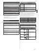
2. 4. 2. Limitation of refrigerant piping length 2. 4. System con¿guration CAUTION Layout example for the indoor units and outdoor unit The total maximum pipe lengths and height difference of this product are shown in the table. If the units are further apart than this, correct operation cannot be guaranteed. OUTDOOR UNIT:24 type Power source 208/230 V ~ 60 Hz Power cable 24 type Total max.
2. 4. 4. Limitation of refrigerant piping length OUTDOOR UNIT:18 type Power source 208/230 V ~ 60 Hz Power cable CAUTION UNIT B 7-12 b The total maximum pipe lengths and height difference of this product are shown in the table. If the units are further apart than this, correct operation cannot be guaranteed. Connection cable 18 type H1 H2 OUTDOOR UNIT Refrigerant pipe UNIT A 7-12 a 50 m (164 ft)*1 Total max. length (a+b) H1 INDOOR UNITS 2. 4. 3.
3. 2. Drain installation 3. INSTALLATION WORK Please obtain the approval of the customer when selecting the location of installation and installing the unit. 3. 1. Selecting an installation location WARNING Securely install the outdoor unit at a location that can withstand the weight of the unit. Otherwise, the outdoor unit may fall and cause injury. Be sure to install the outdoor unit as prescribed, so that it can withstand earthquakes and typhoons or other strong winds.
3. 4. Transportation of the unit • When there are obstacles at the back and front sides. WARNING Do not touch the ¿ns. Otherwise, personal injury could result. CAUTION When carrying the unit, hold the handles on the right and left sides and be careful. If the outdoor unit is carried from the bottom, hands or ¿ngers may be pinched. • Be sure to hold the handles on the sides of the unit. Otherwise, holding the suction grille on the sides of the unit may cause deformation. ) in.
(1) Detach the caps and plugs from the pipes. 4. PIPE INSTALLATION - 1 (2) Center the pipe against the port on the outdoor unit, and then turn the Àare nut by hand. 4. 1. Flare connection (pipe connection) CAUTION To prevent gas leakage, coat the Àare surface with alkylbenzene oil (HAB). Do not use mineral oil. Do not use mineral oil on a Àared part. Prevent mineral oil from getting into the system as this would reduce the lifetime of the units.
5. 2. Electrical requirement 5. ELECTRICAL WIRING CAUTION 5. 1. The precautions of electrical wiring Be sure to install a breaker of the speci¿ed capacity. WARNING Wiring connections must be performed by a quali¿ed person in accordance with speci¿cations. The rated supply of this product is 60Hz, 208/230V. Use a voltage within the range of 187-253V. Regulation of cables and breaker differs from each locality, refer in accordance with local rules.
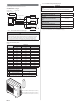
5. 4. Connection diagrams 5. 5. Outdoor unit (1) Service cover removal 24 type OUTSIDE OUTDOOR UNIT INDOOR UNIT A (Inter-unit) Power lines TERMINAL 208/230 V 1 208/230 V 2 208/230 V 3 Grounding DISCONNECT SWITCH G line (FIELD SUPPLY) INDOOR UNIT B TERMINAL 208/230 V 1 208/230 V 2 208/230 V 3 DISCONNECT SWITCH Grounding G line (FIELD SUPPLY) INDOOR UNIT C TERMINAL 208/230 V 1 208/230 V 2 208/230 V 3 DISCONNECT SWITCH Grounding G line (FIELD SUPPLY) • Remove the two mounting screws.
24 type 6. PIPE INSTALLATION - 2 6. 1. Vacuum CAUTION Always use a vacuum pump to purge the air. Refrigerant for purging the air is not charged in the outdoor unit at the factory. Refrigerant must not be discharged into atmosphere. Use a vacuum pump, gauge manifold and charge hose for R410A exclusively. Using the same vacuum for different refrigerants may damage the vacuum pump or the unit. After connecting the piping, check the joints for gas leakage with gas leak detector or soapy water. Power cord 6.
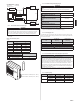
6. 2. Additional charging Refrigerant suitable for a total piping length of 98 ft is charged in the outdoor unit at the factory. When the piping is longer than 98 ft, additional charging is necessary. For the additional amount, see the table below. Hexagon wrench Blank cap Charging port Total piping length 30m (98 ft) 40m (131 ft) 50m (164 ft) Additional refrigerant None 200g (7.1 oz) 400g (14.1 oz) 20g/m (0.
8. TEST RUN The test run method may be different for each indoor unit that is connected. Refer to the installation instruction sheet included with each indoor unit. CAUTION Always turn on the power 12 hours prior to the start of the operation in order to ensure compressor protection. 8. 1.