FUJITSU SEMICONDUCTOR CONTROLLER MANUAL CM25-10153-2E 2 F MC-8L 8-BIT MICROCONTROLLER MB89202/F202RA Series HARDWARE MANUAL
2 F MC-8L 8-BIT MICROCONTROLLER MB89202/F202RA Series HARDWARE MANUAL Be sure to refer to the “Check Sheet” for the latest cautions on development. “Check Sheet” is seen at the following support page URL:http://www.fujitsu.com/global/services/microelectronics/product/micom/support/index.html “Check Sheet” lists the minimal requirement items to be checked to prevent problems beforehand in system development.
PREFACE ■ Purpose of This Manual and Intended Reader The MB89202/F202RA series was developed as one of the general-purpose products of the F2MC-8L family, which contains original 8-bit one-chip microcontrollers for use with ASICs (application specific ICs). The MB89202/F202RA series can be used in a wide range of products from consumer products to industrial products. This manual explains the functions and operations of the MB89202/F202RA series for product development.
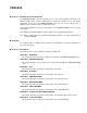
CHAPTER 10 EXTERNAL INTERRUPT CIRCUIT 1 (EDGE) This chapter describes the functions and operation of external interrupt circuit 1 (edge). CHAPTER 11 EXTERNAL INTERRUPT CIRCUIT 2 (LEVEL) This chapter describes the functions and operation of external interrupt circuit 2 (level). CHAPTER 12 A/D CONVERTER This chapter describes the functions and operation of the A/D converter. CHAPTER 13 UART This chapter describes the functions and operation of UART.
• • • • • • • The contents of this document are subject to change without notice. Customers are advised to consult with sales representatives before ordering. The information, such as descriptions of function and application circuit examples, in this document are presented solely for the purpose of reference to show examples of operations and uses of FUJITSU semiconductor device; FUJITSU does not warrant proper operation of the device with respect to use based on such information.
READING THIS MANUAL ■ Example Notation of Register Names and Pin Names ❍ Example notation of register names and bit names By writing 1 into the sleep bit of the standby control register (STBC : SLP), ... Bit name Bit abbreviation Register name Register abbreviation Prohibit the output of interrupt request of the time-base timer (TBTC : TBIE = 0). Setting data Bit abbreviation Register abbreviation If interrupt enabled (CCR : I = 1) is specified, the interrupt is accepted.
CONTENTS CHAPTER 1 1.1 1.2 1.3 1.4 1.5 1.6 1.7 1.8 CHAPTER 2 2.1 HANDLING DEVICES ................................................................................ 17 Precautions on Handling Devices ..................................................................................................... 18 CHAPTER 3 3.1 3.1.1 3.1.2 3.2 3.2.1 3.2.2 3.3 3.4 3.4.1 3.4.2 3.4.3 3.4.4 3.4.5 3.4.6 3.5 3.5.1 3.5.2 3.5.3 3.5.4 3.6 3.6.1 3.6.2 3.6.3 3.6.4 3.6.5 3.7 3.7.1 3.7.2 3.7.3 OVERVIEW ........................
3.7.4 Standby Control Register (STBC) ............................................................................................... 3.7.5 Diagram for State Transition in Standby Mode ............................................................................ 3.7.6 Notes on Standby Mode .............................................................................................................. 3.8 Memory Access Mode ........................................................................................
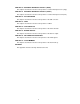
CHAPTER 7 7.1 7.2 7.3 7.4 7.4.1 7.4.2 7.5 7.6 7.7 7.8 7.9 7.10 Overview of 8-bit PWM Timer ......................................................................................................... Configuration of 8-bit PWM Timer .................................................................................................. Pin of 8-bit PWM Timer ................................................................................................................... Registers of 8-bit PWM Timer ..............
CHAPTER 10 EXTERNAL INTERRUPT CIRCUIT 1 (EDGE) ......................................... 225 10.1 Overview of External Interrupt Circuit 1 .......................................................................................... 10.2 Configuration of External Interrupt Circuit 1 .................................................................................... 10.3 Pins of External Interrupt Circuit 1 .................................................................................................. 10.
.4.7 Serial Switch Register (SSEL) ................................................................................................... 13.5 Interrupt of UART ............................................................................................................................ 13.6 Operations of UART Functions ....................................................................................................... 13.6.1 Transmission Operations (Operating Mode 0, 1, 2, and 3) ..........................
CHAPTER 17 FLASH MEMORY ..................................................................................... 357 17.1 Overview of Flash Memory ............................................................................................................. 17.2 Flash Memory Control Status Register (FMCS) ............................................................................. 17.3 Starting the Flash Memory Automatic Algorithm ............................................................................ 17.
Main changes in this edition Page Changes (For details, refer to main body.) - - The followings product name is changed. (MB89202 →MB89202/F202RA) The followings term is changed. (source oscillation →oscillation frequency) 6 1.3 Differences between Models "Notes:" is changed. (The followings sentence is deleted. "• At turning on the power, when the device is used without inputting the external reset, select "reset output supported" and "power-on reset supported" by mask option.
Page Changes (For details, refer to main body.) 310 13.6.3 Reception Operations (Operating Mode 2 Only) "■ Reception Operations (Operating Mode 2 Only)" is changed. ("Note:" is changed.) 358 17.1 Overview of Flash Memory "■ High voltage supply on RST pin (applicable to MB89F202RA only)" is added. 370 17.5.2 Writing Data Figure 17.5-1 is changed. (F555 →F554) 394 B.4 F2MC-8L Instructions List Table B.4-2 is changed. ("No.22 DECW A" is changed.
CHAPTER 1 OVERVIEW This chapter describes the features and basic specification of the MB89202/F202RA series. 1.1 Features of MB89202/F202RA Series 1.2 MB89202/F202RA Series Product Lineup 1.3 Differences between Models 1.4 Block Diagram of MB89202/F202RA Series 1.5 Pin Assignment 1.6 Package Dimensions 1.7 Pin Functions Description 1.
CHAPTER 1 OVERVIEW 1.1 Features of MB89202/F202RA Series The MB89202/F202RA series contains general-purpose single-chip microcontrollers that incorporate a full range of peripheral functions such as A/D converter, UART, PWM timer, PPG, capture timer/counter and external interrupts as well as a compact instruction set.
CHAPTER 1 OVERVIEW • External interrupt 2 (level detection × 8 pins, 1 channel) has eight independent inputs and can be used for wake-up from low-power consumption mode. (L level detection function is supported.) ● Low-power consumption modes (standby modes) • Stop mode (The oscillation is stopped so that current consumption is minimal.) • Sleep mode (The CPU is stopped so that the current consumption is reduced by one-third of normal consumption.
CHAPTER 1 OVERVIEW 1.2 MB89202/F202RA Series Product Lineup Four MB89202 series models are available. Table 1.2-1 shows the models and Table 1.22 shows the CPU and peripheral functions. ■ MB89202/F202RA Series Models Table 1.
CHAPTER 1 OVERVIEW Table 1.2-2 CPU and Peripheral Functions of MB89202/F202RA Series Item Specification Number of basic instructions: Instruction bit length: Instruction length: Data bit length: Minimum instruction execution time: Interrupt processing time: CPU function General-purpose I/O port: Port 26 pins (Also serve as peripherals. 4 of which can be used as N-ch open-drain I/O ports.) 21-bit time-base timer 21 bits Interrupt cycle: 0.66 ms, 2.64 ms, 21 ms, or 335.5 ms with 12.
CHAPTER 1 OVERVIEW 1.3 Differences between Models This section describes the precautions to be taken when selecting a MB89202/F202RA series model. ■ Precautions when Selecting a Model Table 1.
CHAPTER 1 OVERVIEW 1.4 Block Diagram of MB89202/F202RA Series Figure 1.4-1 shows the block diagram of the MB89202/F202RA series. Block Diagram of MB89202/F202RA Series Figure 1.
CHAPTER 1 OVERVIEW 1.5 Pin Assignment Figure 1.5-1 and Figure 1.5-2 show the pin assignment of the MB89202/F202RA series. ■ Pin Assignment of DIP-32P-M06 Figure 1.
CHAPTER 1 OVERVIEW ■ Pin Assignment of FPT-34P-M03 Figure 1.5-2 Pin Assignment of FPT-34P-M03 P04/INT24 1 34 VCC P05/INT25 2 33 P03/INT23/AN7 P06/INT26 3 32 P02/INT22/AN6 P07/INT27 4 31 P01/INT21/AN5 P60 5 30 P00/INT20/AN4 P61 6 29 P43/AN3 * RST 7 28 P42/AN2 * X0 8 27 P41/AN1 * X1 9 26 P40/AN0 * 10 25 P72 * P37/BZ/PPG 11 24 P71 * P36/INT12 12 23 P70 * P35/INT11 13 22 N.C. P34/TO/INT10 14 21 P50/PWM P33/EC 15 20 P30/UCK/SCK N.C.
CHAPTER 1 OVERVIEW 1.6 Package Dimensions Two different packages are available for MB89202/F202RA series. Figure 1.6-1 and Figure 1.6-2 show package dimensions. ■ Package Dimension of DIP-32P-M06 Figure 1.6-1 Package Dimension of DIP-32P-M06 32-pin plastic SH-DIP Lead pitch 1.778 mm Low space 10.16 mm Sealing method Plastic mold (DIP-32P-M06) 32-pin plastic SH-DIP (DIP-32P-M06) Note 1) * : These dimensions do not include resin protrusion.
CHAPTER 1 OVERVIEW ■ Package Dimension of FPT-34P-M03 Figure 1.6-2 Package Dimension of FPT-34P-M03 34-pin plastic SSOP Lead pitch 0.65 mm Package width × package length 6.10 × 11.00 mm Lead shape Gullwing Sealing method Plastic mold Mounting height 1.45 mm MAX Code (Reference) P-SSOP34-6.1×11-0.65 (FPT-34P-M03) 34-pin plastic SSOP (FPT-34P-M03) Note 1) *1 : Resin protrusion. (Each side : +0.15 (.006) Max). Note 2) *2 : These dimensions do not include resin protrusion.
CHAPTER 1 OVERVIEW 1.7 Pin Functions Description Table 1.7-1 describes the I/O pins and functions. The letters in the circuit type column shown in Table 1.7-1 correspond to the letters in the Circuit Type column shown in Table 1.8-1 . ■ Pin Functions Description Table 1.7-1 Pin Functions Description (1/2) Pin No. SHDIP32 *1 *2 SSOP34 Pin name 8 8 X0 9 9 X1 5, 6 5, 6 7 Circuit type Function A Pins for connecting the crystal for the main clock.
CHAPTER 1 OVERVIEW Table 1.7-1 Pin Functions Description (2/2) Pin No. SHDIP32*1 SSOP34*2 Pin name Circuit type Function 17 18 P32/UI/ SI B General-purpose CMOS I/O ports. This pin also serves as the data input pin for the UART or 8-bit serial I/O. The resource is a hysteresis input. 15 15 P33/EC B General-purpose CMOS I/O ports. This pin also serves as the external clock input pin for the 8/16-bit capture timer/counter. The resource is a hysteresis input.
CHAPTER 1 OVERVIEW 1.8 I/O Circuit Types Table 1.8-1 describes the I/O circuit types. The letters in the circuit column shown in Table 1.8-1 correspond to the letters in the circuit type column shown in Table 1.7-1 . ■ I/O Circuit Types Table 1.
CHAPTER 1 OVERVIEW Table 1.
CHAPTER 1 OVERVIEW 16
CHAPTER 2 HANDLING DEVICES This chapter describes the precautions to be taken when handling general-purpose one-chip microcontrollers. 2.
CHAPTER 2 HANDLING DEVICES 2.1 Precautions on Handling Devices This section describes the precautions to be taken when handling the power supply voltage, pins, and other device items. ■ Precautions on Handling Devices ● Ensure that the voltage does not exceed the maximum ratings.
CHAPTER 2 HANDLING DEVICES ● Note to Noise in the External Reset Pin (RST) If the reset pulse applied to the external reset pin (RST) does not meet the specifications, it may cause malfunctions. Use caution so that the reset pulse less than the specifications will not be fed to the external reset pin (RST). ● External pull-up for the External Reset Pin (RST) of MB89F202/F202RA Internal pull-up control for RST is not available for MB89F202/F202RA.
CHAPTER 2 HANDLING DEVICES Figure 2.
CHAPTER 3 CPU This chapter describes the functions and operations of the CPU. 3.1 Memory Space 3.2 Dedicated Register 3.3 General-Purpose Registers 3.4 Interrupts 3.5 Reset 3.6 Clock 3.7 Standby Mode (Low-Power Consumption Mode) 3.
CHAPTER 3 CPU 3.1 Memory Space The MB89202/F202RA series has 64-KB memory space that consists of the I/O area, RAM area, ROM area, and external area. Part of the memory space is applied for specific use such as general-purpose registers or a vector table. ■ Configuration of Memory Space ● I/O area (address: 0000H to 007FH) The control registers and data registers for built-in peripheral functions are assigned.
CHAPTER 3 CPU Memory Map Figure 3.
CHAPTER 3 CPU 3.1.1 Specific-purpose Areas In addition to the I/O area, the general-purpose register area and vector table area are available as areas for specific applications. ■ General-purpose Register Area (Address: 0100H to 01FFH) • This area is used for 8-bit arithmetic operations and transfer. Supplementary registers are provided. • Since this area is allocated to a part of the RAM area, it can also be used as normal RAM.
CHAPTER 3 CPU Table 3.1-1 Vector Table (2/2) Address in the vector table Vector call instruction Upper digits Lower digits IRQB FFE4H FFE5H IRQA FFE6H FFE7H IRQ9 FFE8H FFE9H IRQ8 FFEAH FFEBH IRQ7 FFECH FFEDH IRQ6 FFEEH FFEFH IRQ5 FFF0H FFF1H IRQ4 FFF2H FFF3H IRQ3 FFF4H FFF5H IRQ2 FFF6H FFF7H IRQ1 FFF8H FFF9H IRQ0 FFFAH FFFBH Mode data -* FFFDH Reset vector FFFEH FFFFH *: For MB89202 / MB89V201, FFFCH is prohibited. (Use "FFH".
CHAPTER 3 CPU 3.1.2 Location of 16-bit Data on Memory Upper digits of 16-bit data and stack data are stored in lower addresses on memory. ■ 16-bit Data Storage State on RAM When 16-bit data is written into RAM, the upper byte of the data is stored with a lower address and the lower byte of the data is stored with the next address. 16-bit data is read in the same manner. Figure 3.1-2 shows the location of 16-bit data on RAM. Figure 3.
CHAPTER 3 CPU 3.2 Dedicated Register The dedicated register in the CPU consists of a program counter (PC), two arithmetic operation registers (A and T), three address pointers (IX, EP, and SP), and program status (PS) register. The size of each register is 16 bits. ■ Dedicated Register Configuration The dedicated register in the CPU consists of seven 16-bit registers. Some registers allow only the lower 8 bits to be used. Figure 3.2-1 shows the configuration of the dedicated register. Figure 3.
CHAPTER 3 CPU ● Temporary Accumulator (T) The temporary accumulator is an auxiliary 16-bit arithmetic operation register. It handles arithmetic operations using data in the accumulator (A). When arithmetic operations in the accumulator (A) are handled in word units (16 bits), data in the temporary accumulator is handled in word units. Otherwise, it is handled in byte units (8 bits).
CHAPTER 3 CPU 3.2.1 Condition Code Register (CCR) The condition code register (CCR) is the lower 8 bits of the program status register (PS). The condition code register consists of bits (C, V, Z, N, and H) for indicating the results of arithmetic operations or data to be transferred and control bits (I, IL1, and IL0) for controlling the acceptance of interrupt requests. ■ Configuration of the Condition Code Register (CCR) Figure 3.
CHAPTER 3 CPU Figure 3.2-3 shows how the shift commands change the carry flag. Figure 3.2-3 Change of the Carrier Flag by the Shift Commands - Shift to the left (ROLC) - Shift to the right (RORC) bit7 bit0 bit7 bit0 C C Note: The condition code register is part of the program status register (PS), and thus is not allowed to access only the condition code register. It is uncommon to fetch and use only some of the flag bits directly.
CHAPTER 3 CPU 3.2.2 Register Bank Pointer (RP) The register bank pointer (RP) is the upper 8 bits of the program status register (PS). The register bank pointer indicates the general-purpose register bank address being used, and the address is converted to the actual address in general-purpose register addressing. ■ Configuration of the Register Bank Pointer (RP) Figure 3.2-4 shows the configuration of the register bank pointer. Figure 3.
CHAPTER 3 CPU 3.3 General-Purpose Registers The general-purpose registers are memory blocks. Eight 8-bits comprise a bank. The register bank pointer (RP) specifies a register bank. Although up to 32 banks can be used, some banks can be expanded onto external RAM if the capacity of internal RAM is not sufficient for all 32 banks. The general-purpose registers are effective for processing interrupts, vector calls, or subroutine calls.
CHAPTER 3 CPU ■ Features of the General-purpose Registers The general-purpose registers have the following features: • High-speed access with short instructions (general-purpose register addressing) • Register banks (in blocks) that allow data to be easily conserved and partitioned in the unit of function The general-purpose registers allow specific register banks to be statically assigned with the interrupt processing routine or vector call (CALLV #0 to #7) processing routine.
CHAPTER 3 CPU 3.4 Interrupts The MB89202/F202RA series supports 12 interrupt request inputs corresponding to peripheral functions and allows an interrupt level to be assigned to each of the inputs. The interrupt controller compares levels of interrupts generated by peripheral functions when output of interrupt requests is allowed for peripheral functions. The CPU performs the interrupt operation according to its interrupt acceptance settings.
CHAPTER 3 CPU Table 3.
CHAPTER 3 CPU 3.4.1 Interrupt Level Setting Registers (ILR1 to ILR4) For the interrupt level setting registers (ILR1, 2, 3, and 4), 16 two-bit data items corresponding to interrupt requests sent from peripheral functions are assigned. Interrupt levels can be specified in these 2-bits (interrupt level setting bits). ■ Configuration of the Interrupt Level Setting Registers (ILR1 to ILR4) Figure 3.
CHAPTER 3 CPU 3.4.2 Steps in the Interrupt Operation When an interrupt request is generated in a peripheral function, the interrupt controller notifies the CPU of its interrupt level. If the CPU can accept an interrupt, the CPU temporarily stops the program that is handling and starts the interrupt processing routine.
CHAPTER 3 CPU ➃ The interrupt controller is always monitoring interrupt requests from peripheral functions. The interrupt controller notifies the CPU of the highest interrupt level interrupt among levels corresponding to interrupt requests currently generated. If different requests are made with the same interrupt level, the interrupt controller also determines their priorities.
CHAPTER 3 CPU 3.4.3 Multiple Interrupts Multiple interrupts are allowed by setting different levels into the interrupt level setting registers (ILR1 to ILR4) for multiple interrupt requests from peripheral functions. ■ Multiple Interrupts When an interrupt request with a higher interrupt level is generated while the interrupt processing routine is operating, the current interrupt processing cycle is stopped to accept the higher-level interrupt request. Interrupt levels 1, 2, and 3 can be specified.
CHAPTER 3 CPU 3.4.4 Interrupt Processing Time From when an interrupt request is generated to when control is transferred to the interrupt processing routine, both the time to quit the instruction being executed and the time to manage the interrupt (required to prepare interrupt processing) are required. The total time must be within 30 instruction cycles.
CHAPTER 3 CPU 3.4.5 Stack Operation at Interrupt Processing This section describes how values in registers are saved and restored at interrupt processing. ■ Stack Operation at the Beginning of Interrupt Processing After accepting an interrupt, the CPU automatically saves the values in the program counter (PC) and program status (PS) in the stack. Figure 3.4-5 shows the stack operation at the beginning of interrupt processing. Figure 3.
CHAPTER 3 CPU 3.4.6 Stack Area for Interrupt Processing A stack area on RAM is used for interrupt processing. The value in the stack pointer (SP) is used as the start address of the stack area. ■ Stack Area for Interrupt Processing The stack area is used to save/restore the value in the program counter (PC) when executing the subroutine call instruction (CALL) or vector call instruction (CALLV) or temporarily save and restore values in registers or other storage with the PUSHW and POPW instruction.
CHAPTER 3 CPU 3.5 Reset There are four sources of reset: • External reset • Software reset • Watchdog reset • Power-on reset Oscillation stabilization wait time is not applied in some operating modes when a reset occurs or in some option settings. ■ Reset Sources Table 3.5-1 Reset Sources Reset source Reset condition External reset The external reset pin is "L" level. Software reset "0" is written into the software reset bit in the standby control register (STBC: RST).
CHAPTER 3 CPU ● Power-on reset Power-on reset occurs when power is turned on. Power-on reset occurs after oscillation stabilization wait time has expired. Power-on reset requires an external reset circuit. ■ Reset Sources and Oscillation Stabilization Wait Time Operations in oscillation stabilization wait time depend on the operating mode used when a reset occurs. After a reset, active mode is set regardless of the operating mode applied before the reset (standby mode) and reset source.
CHAPTER 3 CPU 3.5.1 Reset Flag Register (RSFR) The reset flag register (RSFR) allows confirmation of the source for a generated reset. ■ Configuration of the Reset Flag Register (RSFR) Figure 3.5-1 Configuration of Reset Flag Register (RSFR) Address bit7 bit6 bit5 bit4 bit3 bit2 bit1 000EH PONR ERST WDOG SFTR R R R bit0 Initial value XXXX----B R SFTR 0 1 WDOG 0 1 ERST Software reset flag bit When written When read The source is software reset.
CHAPTER 3 CPU Table 3.5-3 Explanation of Functions of Each Bit in the Reset Flag Register (RSFR) Bit name Description PONR: Power-on reset flag bit "1" is set to this bit when power-on reset occurs. "1" is set to this bit after power is turned on. This bit is cleared with "0" after being read. Writing a value to this bit has no significance. bit6 ERST: External reset flag bit "1" is set to this bit when external reset occurs.
CHAPTER 3 CPU 3.5.2 External Reset Pin The external reset pin generates a reset by "L" level input. When an option setting for enabling reset output is selected, the "L" level signal is output depending on the internal reset source. ■ Block Diagram of External Reset Pin The external reset pin (RST) on models with supported reset output has hysteresis input and pull-up N-ch open drain output. The external reset pin on models without supported reset output is used only as the pin dedicated to reset input.
CHAPTER 3 CPU 3.5.3 Reset Operation The CPU reads the mode data (mode fetch) and reset vector from internal ROM according to the mode pin settings following the cancellation of a reset. For a return triggered by a reset when power is turned on and in stop mode, the CPU fetches the mode after oscillation stabilization wait time has expired. When a reset occurs, the contents in RAM cannot be guaranteed. ■ Overview of the Reset Operation Figure 3.
CHAPTER 3 CPU ■ Mode Fetch The CPU reads the mode data and reset vector from internal ROM following the cancellation of the reset. ● Mode data (address: FFFDH) Set single-chip mode (00H) to the mode data. ● Reset vector (address: FFFEH (highest)/FFFFH (lowest)) Specify the address at which execution is to be started after the reset operation is completed. The CPU starts executing instructions from the specified address.
CHAPTER 3 CPU 3.5.4 State of Each Pin at Reset The state of each pin is initialized by a reset. ■ States of Pins during Reset When a reset occurs, most I/O pins (resource pins) become Hi-Z, and the CPU reads the mode data from internal ROM. ■ States of Pins after the CPU Reads the Mode Data Most of the I/O pins remain Hi-Z immediately after the CPU reads the mode data. For pin states established by something other than a reset, see "APPENDIX E Pin State of the MB89202/ F202RA Series " for details.
CHAPTER 3 CPU 3.6 Clock The clock generator includes the oscillation circuit. A high-speed clock is generated by connecting an external resonator for oscillation frequency. Alternatively, when the clock is supplied from an external source, a clock signal can be connected to the clock input pin. The clock controller manages the speed and supply of the clock in active mode and standby mode.
CHAPTER 3 CPU Figure 3.
CHAPTER 3 CPU 3.6.1 Clock Generator The clock generator enables oscillation in active mode and disables oscillation in stop mode. ■ Clock Generator ● For a crystal resonator or ceramic resonator Connect it as shown in Figure 3.6-2 . Figure 3.6-2 Example of Connecting a Crystal Resonator or Ceramic Resonator MB89202/F202RA series Oscillation circuit X0 X1 ● For an external clock Connect it to the X0 pin and open the X1 pin as shown in Figure 3.6-3 . Figure 3.
CHAPTER 3 CPU 3.6.2 Clock Controller The clock controller consists of the following six blocks: • Oscillation circuit • System clock selector • Clock controller • Oscillation stabilization wait time selector • System clock control register (SYCC) • Standby control register (STBC) ■ Block Diagram of Clock Controller Figure 3.6-4 is a block diagram of the clock controller. Figure 3.
CHAPTER 3 CPU ● Oscillator Oscillation circuit that halts oscillation in stop mode. ● System clock selector Selects one of four frequency-divided source clocks to be supplied to the clock control circuit. ● Clock controller Controls the operating clock supplied to the CPU and peripheral circuits according to the active (RUN) mode and standby mode (sleep, stop). It also stops supply of the clock to the CPU until the clock supply stop signal for the oscillation stabilization wait time selector is cancelled.
CHAPTER 3 CPU 3.6.3 System Clock Control Register (SYCC) The system clock control register (SYCC) manages clock settings such as selection of the clock speed and oscillation stabilization wait time. ■ Configuration of the System Clock Control Register (SYCC) Figure 3.
CHAPTER 3 CPU Table 3.6-1 Explanation of Functions of Each Bit in the System Clock Control Register (SYCC) Bit name ■ Description bit7 SCM: System clock monitor bit Used to check the current clock mode. When this bit is 0, the clock is stopping or waiting for stabilization of oscillation. When this bit is 1, operations are performed in active mode. Note: This bit is read-only enabled. Writing a value to this bit does not affect operation.
CHAPTER 3 CPU 3.6.4 Clock Mode The clock speed is switched by selecting one of four frequency-divided source clocks (gears). ■ Operations in Each Clock Mode Table 3.
CHAPTER 3 CPU ■ Operations in Active Mode In active (RUN) mode, the oscillator is generating a clock. The CPU, time-base timer, and other peripheral circuits operate using the clock. In active mode, all clock speeds except the time-base timer clock speed can be changed (using gears). In active mode, specifying standby mode results in a transition to sleep mode or stop mode. Operations always start in RUN mode after a reset (any type). (Operating modes are cancelled by a reset.
CHAPTER 3 CPU 3.6.5 Oscillation Stabilization Wait Time Oscillation stabilization wait time is to be applied when power is turned on to start the clock in RUN mode while the clock is stopped in stop mode. ■ Oscillation Stabilization Wait Time A ceramic or crystal resonator normally requires several or several tens of milli-seconds from oscillation start to oscillation stabilization at a specific cycle (oscillation frequency).
CHAPTER 3 CPU ● Oscillation stabilization wait time at a reset Option settings specify oscillation stabilization wait time at a reset (initial values of WT1 and WT0). Cancellation of stop mode by external reset also applies oscillation stabilization wait time. Table 3.6-3 shows the relationship between the active mode operation start conditions and oscillation stabilization wait time. Table 3.
CHAPTER 3 CPU 3.7 Standby Mode (Low-Power Consumption Mode) The MB89202/F202RA series supports sleep mode and stop mode in standby mode. Transition to standby mode is controlled by the standby control register (STBC) settings. In active mode, transition to sleep mode or stop mode is allowed. In standby mode, operation of the CPU and peripheral functions is stopped to reduce power consumption.
CHAPTER 3 CPU 3.7.1 Operations in Standby Mode This section describes CPU and peripheral function operation in standby mode. ■ Operations in Standby Mode Table 3.
CHAPTER 3 CPU 3.7.2 Sleep Mode This section describes sleep mode. ■ Operations Relating to Sleep Mode ● Transition to sleep mode In sleep mode, the operating clock for CPU is stopped. Although the CPU stops storing data in the registers and RAM used immediately before transition to sleep mode, peripheral functions, excepting the watchdog timer, continue to operate. Writing "1" to the sleep bit in the standby control register (STBC: SLP) results in a transition to sleep mode.
CHAPTER 3 CPU 3.7.3 Stop Mode This section describes the stop mode. ■ Operations Relating to Stop Mode ● Transition to stop mode In stop mode, the oscillation frequency is stopped. Most functions stop storing data in the registers and RAM used immediately before transition to stop mode. The clock circuit stops oscillating, the peripheral functions and CPU stop operating, but the external interrupt circuit continues to operate.
CHAPTER 3 CPU 3.7.4 Standby Control Register (STBC) The standby control register (STBC) controls transition to sleep /stop modes, pin state settings in stop mode, and software reset. ■ Standby Control Register (STBC) Figure 3.
CHAPTER 3 CPU Table 3.7-2 Explanation of Functions of Each Bit in the Standby Control Register (STBC) Bit name Description bit7 STP: Stop bit This bit specifies transition to stop mode. Writing "1" into this bit allows transition to stop mode. Writing "0" into this bit does not affect operations. This bit is always read with the value of "0". bit6 SLP: Sleep bit This bit specifies transition to sleep mode. Writing "1" into this bit allows transition to sleep mode.
CHAPTER 3 CPU 3.7.5 Diagram for State Transition in Standby Mode Figure 3.7-2 shows the state transition diagram in standby mode. ■ Diagram for State Transition in Standby Mode Figure 3.
CHAPTER 3 CPU ● Transition to and cancellation of clock mode (non-standby mode) Table 3.7-3 Transition to and Cancellation of Clock Mode State transition Transition conditions Transition to active mode after power-on reset (9) End of oscillation stabilization wait time (output of time-base timer) (1) Cancellation of reset input Reset in RUN mode (2) External reset, software reset, or watchdog reset ● Transition to and cancellation of standby mode Table 3.
CHAPTER 3 CPU 3.7.6 Notes on Standby Mode Even if the standby control register (STBC) sets standby mode, transition to standby mode is not allowed when a peripheral function generates an interrupt request. When an interrupt causes a return from standby mode to active mode, subsequent operations depend on whether interrupt requests are acceptable.
CHAPTER 3 CPU ■ Oscillation Stabilization Wait Time The oscillator for oscillation frequency stops in stop mode, thus oscillation stabilization wait time must be applied after the oscillator is activated. Use one of three clock oscillation stabilization wait time settings generated by the time-base timer. If the interval selected for the time-base timer is shorter than the oscillation stabilization wait time, an interval timer interrupt request is generated during oscillation stabilization wait time.
CHAPTER 3 CPU 3.8 Memory Access Mode The MB89202/F202RA series supports only single-chip mode for access to memory. ■ Single-chip Mode In single-chip mode, only internal RAM and ROM are used. The CPU can access only the internal I/O area, RAM area, and ROM area. ■ Mode Data Set 00H into the mode data in internal ROM to select single-chip mode. Figure 3.
CHAPTER 3 CPU Figure 3.8-2 Operations for Selecting Memory Access Source of a reset is generated. I/O pins are high impedance. Wait for cancellation of the reset source (external reset or oscillation stabilization wait time) Being reset Mode data and reset vector are fetched from internal ROM.
CHAPTER 3 CPU 74
CHAPTER 4 I/O PORTS This chapter describes the functions and operations of I/O ports. 4.1 Overview of I/O Ports 4.2 Port 0 4.3 Port 3 4.4 Port 4 4.5 Port 5 4.6 Port 6 4.7 Port 7 4.
CHAPTER 4 I/O PORTS 4.1 Overview of I/O Ports Six I/O ports (comprising 26 pins) are available as general-purpose I/O ports (parallel I/O ports). These ports also serve peripherals (as I/O pins for specific peripheral functions). ■ Functions of I/O Ports The I/O ports function to output data from the CPU to I/O pins via their port data register (PDR) and send signals input to I/O pins to the CPU.
CHAPTER 4 I/O PORTS Table 4.
CHAPTER 4 I/O PORTS 4.2 Port 0 Port 0 is a general-purpose I/O port and may also serve as peripheral inputs. The pins of this port can be used for peripherals or normal port function that can be selected according to the setting of a bit corresponding to the pin on a specific register. This section mainly explains the general-purpose I/O function of the port. This section also describes the structure, pins, and associated registers of port 0 and provides a block diagram of pins.
CHAPTER 4 I/O PORTS ■ Block Diagram of Port 0 Figure 4.
CHAPTER 4 I/O PORTS 4.2.1 Registers of Port 0 (PDR0, DDR0, and PUL0) This section describes the registers associated with port 0. ■ Functions of Port 0 Registers ● Port 0 data register (PDR0) The PDR0 register indicates the state of the output latch. For a pin set to function as an output port, the same value ("0" or "1") as the value state of the output pin can be read from this register. If the pin is set to function as an input port, however, its output latch value cannot be read from the register.
CHAPTER 4 I/O PORTS Table 4.2-3 lists the functions of the port 0 registers. Table 4.2-3 Functions of Port 0 Registers Register name When being read Data 0 Pin state is "L" level. Output latch of "0" is set and "L" level is output to the pin in output port mode. Pin state is "H" level. Output latch of "1" is set and "H" level is output to the pin in output port mode.
CHAPTER 4 I/O PORTS 4.2.2 Operations of Port 0 Functions This section describes the operation of port 0. ■ Operation of Port 0 ● Operation in output port mode When "1" is written to a bit of the DDR0 register, the bit corresponding to a pin of port 0, the pin functions as an output port. In output port mode, the output transistor operation is enabled and the output latch data is output to the pin.
CHAPTER 4 I/O PORTS ● Operation in stop mode When the pin state setting bit of the standby control register (STBC: SPL) is "1" and when the stop mode is entered, the output transistor is turned OFF and the pin becomes Hi-Z because the output transistor is forcibly turned OFF without respect to the value existing on the DDR0 register in the bit position corresponding to the pin. Input remains fixed to prevent leaks by input open. Table 4.2-4 summarizes the operating modes of the pins of port 0. Table 4.
CHAPTER 4 I/O PORTS 4.3 Port 3 Port 3 is a general-purpose I/O port and may also serve as input pins for external interrupts as well as input and output pins for peripherals. This section mainly explains the general-purpose I/O function of the port. This section also describes port 3 concerning to the structure, pins, a block diagram of pins, and associated registers.
CHAPTER 4 I/O PORTS ■ Block Diagram of Port 3 Figure 4.
CHAPTER 4 I/O PORTS 4.3.1 Registers of Port 3 (PDR3, DDR3, PUL3) This section describes the registers associated with port 3. ■ Functions of Port 3 Registers ● Port 3 data register (PDR3) The PDR3 register indicates the state of the pins. For a pin set to function as an output port, the same value ("0" or "1") as held by the output latch can be read from this register. If the pin is set to function as an input port, however, its output latch value cannot be read from the register.
CHAPTER 4 I/O PORTS Table 4.3-3 lists the functions of port 3 registers. Table 4.3-3 Functions of Port 3 Registers Register name Data 0 Port 3 data register (PDR3) 1 Port 3 data direction register (DDR3) When being read When being written Pin state is "L" level. Output latch of "0" is set and "L" level is output to the pin in output port mode. Pin state is "H" level. Output latch of "1" is set and "H" level is output to the pin in output port mode.
CHAPTER 4 I/O PORTS 4.3.2 Operations of Port 3 Functions This section describes the operation of port 3. ■ Operation of Port 3 ● Operation in output port mode When "1" is written for a bit of the DDR3 register, the bit corresponding to a pin of port 3, the pin functions as an output port. In output port mode, output transistor operation is enabled and output latch data is output to the pin.
CHAPTER 4 I/O PORTS ● Operation when a reset is performed When the CPU is reset, the bits of the DDR3 register are initialized to "0", at which time the output transistors become OFF (input port mode) and the pins become Hi-Z. However, CPU resets do not initialize the PDR3 register.
CHAPTER 4 I/O PORTS 4.4 Port 4 Port 4 is a type of I/O port that is switched between CMOS push-pull and N-ch opendrain and may also serve analog inputs. Each pin of this port can be used for peripherals or normal port function that can be selected according to the setting of the bit corresponding to the pin on a specific register. This section explains the I/O port function of CMOS push-pull/ N-ch open-drain type.
CHAPTER 4 I/O PORTS ■ Block Diagram of Port 4 Figure 4.4-1 Block Diagram of Port 4 A/D converter channel select A/D converter enable bit To A/D converter's analog input PDR Stop mode (SPL = 1) Internal data bus PDR read PDR read (when read-modify-write is performed) Pch Output latch PDR write DDR write Pins Nch DDR Stop mode (SPL = 1) DDR read OUT read OUT OUT write ■ Registers of Port 4 The registers PDR4, DDR4, and OUT4 are associated with port 4.
CHAPTER 4 I/O PORTS 4.4.1 Registers of Port 4 (PDR4) This section describes the registers associated with port 4. ■ Functions of Port 4 Registers ● Port 4 data register (PDR4) The PDR4 register indicates the state of the pins. For a pin set to function as an output port, the same value ("0"or "1") as held by the output latch can be read from this register. If the pin is set to function as an input port, however, its output latch value cannot be read from the register.
CHAPTER 4 I/O PORTS 4.4.2 Operations of Port 4 Functions This section describes the operation of port 4. ■ Operation of Port 4 ● Operation in output port mode When "1" is written for a bit of the DDR4 register, the bit corresponding to a pin of port 4, the pin functions as an output port. In output port mode, the output transistor operation is enabled and output latch data is output to the pin.
CHAPTER 4 I/O PORTS 4.5 Port 5 Port 5 is a general-purpose I/O port and may also serve the input/output for peripherals. The pins of this port can be used for peripherals or normal port function that can be selected according to the setting of the bit corresponding to the pin on a specific register. This section explains the general-purpose I/O function of the port. This section also describes port 5 concerning to the structure, pins, a block diagram of pins, and associated registers.
CHAPTER 4 I/O PORTS ■ Block Diagram of Port 5 Figure 4.5-1 Block Diagram of Port 5 PDR Stop mode (SPL = 1) Pull-up resistor Internal data bus PDR read Output from peripheral Output enable from peripheral PDR read (when read-modify-write is performed) P-ch Output latch PDR write Pin N-ch DDR DDR write Stop mode (SPL = 1) DDR read PUL read PUL PUL write ■ Registers of Port 5 The registers PDR5, DDR5, and PUL5 are associated with port 5.
CHAPTER 4 I/O PORTS 4.5.1 Registers of Port 5 (PDR5, DDR5, PUL5) This section describes the registers associated with port 5. ■ Functions of Port 5 Registers ● Port 5 data register (PDR5) The PDR5 register indicates the state of pins. For a pin set to function as an output port, the same value ("0" or "1") as held by the output latch can be read from this register. If the pin is set to function as an input port, however, its output latch value cannot be read from the register.
CHAPTER 4 I/O PORTS Table 4.5-3 Functions of Port 5 Registers Register name When being read Data 0 Pin state is "L" level. Output latch of "0" is set and "L" level is output to the pin in output port mode. Pin state is "H" level. Output latch of "1" is set and the pin in output port mode is set at Hi-Z. Input port pin The pin is set to function as an input pin with output transistor operation disabled.
CHAPTER 4 I/O PORTS 4.5.2 Operations of Port 5 Functions This section describes the operation of port 5. ■ Operation of Port 5 ● Operation in output port mode When "1" is written for a bit of the DDR5 register, the bit corresponding to the pin of port 5, the pin functions as an output port. In output port mode, the output transistor operation is enabled and the output latch data is output to the pin.
CHAPTER 4 I/O PORTS Table 4.5-4 summarizes the operating modes of the pin of port 5. Table 4.
CHAPTER 4 I/O PORTS 4.6 Port 6 Port 6 is a general-purpose I/O port. This section describes the port function when operating as general-purpose I/O port. This section also describes the structure, pins, the block diagram of pins, and associated registers of port 6.
CHAPTER 4 I/O PORTS Block Diagram of Port 6 Figure 4.
CHAPTER 4 I/O PORTS ■ Registers PDR6, DDR6, and PUL6 of Port 6 Registers PDR6, DDR6, and PUL6 are associated with port 6. The bits of these registers correspond to the pins of port 6 in one-to-one correspondence. Table 4.6-2 tabulates the correspondence between the pins and the bits of the port 6 registers. Table 4.
CHAPTER 4 I/O PORTS 4.6.1 Registers of Port 6 (PDR6, DDR6, PUL6) This section describes the registers associated with port 6. ■ Functions of Port 6 Registers ● Port 6 data register The PDR6 register indicates the state of the output latch. For a pin set to function as an output port, the same value ("0" or "1") as the value state of the output pin can be read from this register. If the pin is set to function as an input port, however, its output latch value cannot be read from the register.
CHAPTER 4 I/O PORTS ● Port 6 pull-up setting register (PUL6) The bits of the pull-up setting register correspond to the pins of port 6 in one-to-one correspondence. When the pull-up resistor is selected by using the pull-up setting register, the pin will be at "H" level (pull-up state) instead of Hi-Z during stop (SPL = 1). During a reset, however, the pull-up is invalid and the pin remains at Hi-Z. Figure 4.
CHAPTER 4 I/O PORTS 4.6.2 Operations of Port 6 Functions This section describes the operation of port 6. ■ Operation of Port 6 ● Operation in output port mode When "1" is written for a bit of the DDR6 register, the bit corresponding to a pin of port 6, the pin functions as an output port. In output port mode, the output transistor operation is enabled and the output latch data is output to the pin.
CHAPTER 4 I/O PORTS Table 4.6-4 Operating Modes of Pins of Port 6 Pin name Normal operation, sleep, stop (SPL = 0) P60, P61 General-purpose I/O port Stop (SPL = 1) At a reset Hi-Z Hi-Z Note: When the pull-up resistor is selected by using the pull-up setting register, the pin state will be "H" level instead of Hi-Z in stop mode (SPL = 1). During a reset, however, the pull-up is invalid with the pin remaining at Hi-Z.
CHAPTER 4 I/O PORTS 4.7 Port 7 Port 7 is a general-purpose I/O port. This section describes the port function when operating as general-purpose I/O port. This section also describes the port structure, pins, the pin block diagram associated registers of port 7.
CHAPTER 4 I/O PORTS ■ Block Diagram of Port 7 Figure 4.7-1 Block Diagram of Port 7 PDR Stop mode (SPL = 1) Pull-up resistor Internal data bus PDR read PDR read (when read-modify-write is performed) Pch Output latch PDR write Pin Nch DDR DDR write Stop mode (SPL = 1) DDR read PUL read PUL PUL write ■ Registers PDR7, DDR7, and PUL7 of Port 7 Registers PDR7, DDR7, and PUL7 are associated with port 7. The bits of these registers correspond to the pins of port 7 in one-to-one correspondence.
CHAPTER 4 I/O PORTS 4.7.1 Registers of Port 7 (PDR7, DDR7, PUL7) This section describes the registers associated with port 7. ■ Functions of Port 7 Registers ● Port 7 data register (PDR7) The PDR7 register indicates the state of the output latch. For a pin set to function as an output port, the same value ("0" or "1") as the value state of the output pin can be read from this register. If the pin is set to function as an input port, however, its output latch value cannot be read from the register.
CHAPTER 4 I/O PORTS ● Port 7 pull-up setting register (PUL7) The bits of the pull-up setting register correspond to the pins of port 7 in one-to-one correspondence. When the pull-up resistor is selected by using the pull-up setting register, the pin will be at "H" level (pull-up state) instead of Hi-Z during stop (SPL = 1). During a reset, however, the pull-up is invalid and the pin remains at Hi-Z. Figure 4.
CHAPTER 4 I/O PORTS 4.7.2 Operations of Port 7 Functions This section describes the operation of port 7. ■ Operation of Port 7 ● Operation in output port mode When "1" is written for a bit of the DDR7 register, the bit corresponding to a pin of port 7, the pin functions as an output port. In output port mode, the output transistor operation is enabled and the output latch data is output to the pin.
CHAPTER 4 I/O PORTS Table 4.7-4 summarizes the operating modes of the pins of port 7. Table 4.7-4 Operating Modes of Pins of Port 7 Pin name Normal operation, sleep, stop (SPL = 0) P70 to P72 General-purpose I/O port Stop (SPL = 1) At a reset Hi-Z Hi-Z Note: When the pull-up resistor is selected by using the pull-up setting register, the pin state will be "H" level instead of Hi-Z in stop mode (SPL = 1). During a reset, however, the pull-up is invalid with the pin remaining at Hi-Z.
CHAPTER 4 I/O PORTS 4.8 Programming Example of I/O Port This section provides an example of programming with I/O ports. ■ I/O Port Programming Example ● Processing specification Ports 0 and 3 are used to light all seven segments of LED (eight segments if the decimal point is included). Pin P00 is connected to the anode common pin of LED and pins P30 to P37 are connected to the pins of the segments. Figure 4.8-1 provides an example of the pins and the 8-segment LED connected. Figure 4.
CHAPTER 4 I/O PORTS ● Coding example PDR0 EQU 0000H ; Address of port 0 data register DDR0 EQU 0001H ; Address of port 0 data direction register PDR3 EQU 000CH ; Address of port 3 data register DDR3 EQU 000DH ; Address of port 3 data direction register ;------------------------------Main program----------------------------------------------------------------------CSEG ; [CODE SEGMENT] : CLRB PDR0:0 ; Set P00 at "L" level. MOV PDR3,#11111111B ; Set all pins of port 3 at "H" level.
CHAPTER 5 TIME-BASE TIMER This chapter describes the functions and operations of the time-base timer. 5.1 Overview of Time-base Timer 5.2 Configuration of Time-base Timer 5.3 Time-base Timer Control Register (TBTC) 5.4 Interrupt of Time-base Timer 5.5 Operations of Time-base Timer Functions 5.6 Notes on Using Time-base Timer 5.
CHAPTER 5 TIME-BASE TIMER 5.1 Overview of Time-base Timer The time-base timer functions as an interval timer. The time-base timer is a 21-bit freerun counter that counts up in synchronization with the internal count clock (at the oscillation frequency divided by 2). The timer also has an interval timer function to select one of four time intervals. In addition, it provides timer output for oscillation stabilization time and an operation clock for the watchdog timer.
CHAPTER 5 TIME-BASE TIMER Table 5.1-2 Clock Cycles Supplied by Time-base Timer (2/2) Clock supplied to Clock cycle 222/FCH (Approximately 335.5 ms) Watchdog timer 28/FCH (Approximately 20.5 µs) A/D converter Remarks Watchdog timer count up clock Continuous activation clock FCH: Oscillation frequency The values enclosed in parentheses are time intervals when the oscillation frequency is 12.5 MHz.
CHAPTER 5 TIME-BASE TIMER 5.2 Configuration of Time-base Timer The time-base timer consists of the following four function blocks. • Time-base counter • Counter clear circuit • Interval timer selector • Time-base timer control register (TBTC) ■ Block Diagram of Time-base Timer Figure 5.
CHAPTER 5 TIME-BASE TIMER 5.3 Time-base Timer Control Register (TBTC) The time-base timer control register (TBTC) selects a time interval, clears the counter, controls interrupts, or checks the status. ■ Time-base Timer Control Register (TBTC) Figure 5.3-1 Time-base Timer Control Register (TBTC) Address bit7 bit6 bit5 000AH TBOF TBIE R/W R/W bit4 bit3 bit2 bit1 bit0 TBC1 TBC0 TBR R/W R/W TBR 0 1 Initial value 00---000B R/W Time-base timer initialization bit Read "1" is always read.
CHAPTER 5 TIME-BASE TIMER Table 5.3-1 Explanation of Functions of Each Bit in Time-base Timer Control Register (TBTC) Bit name Description • bit7 TBOF: Overflow interrupt request flag bit • • This bit is set to "1" when the specified bit of the time-base timer counter overflows. An interrupt request is sent when this bit and the interrupt request enable bit (TBIE) are both "1". While this bit is written, it is cleared when "0" is specified, and nothing is changed and affected when "1" is specified.
CHAPTER 5 TIME-BASE TIMER 5.4 Interrupt of Time-base Timer The time-base timer counter generates an interrupt when the specified bit of the counter overflows (interval timer function). ■ Interrupts when the Interval Timer Function is Enabled The counter counts up with the internal count clock. When the specified interval timer bit overflows, the overflow interrupt request flag bit (TBTC: TBOF) is set to "1".
CHAPTER 5 TIME-BASE TIMER 5.5 Operations of Time-base Timer Functions The time-base timer functions as an interval timer or supplies clocks to some peripherals. ■ Operations of Interval Timer Function (Time-base Timer) To use as an interval timer, the settings shown below must be made. Figure 5.
CHAPTER 5 TIME-BASE TIMER Figure 5.
CHAPTER 5 TIME-BASE TIMER 5.6 Notes on Using Time-base Timer Notes on using the time-base timer are shown below. ■ Notes on Using Time-base Timer ● Notes on using programs to set time-base timer When the interrupt request flag bit (TBTC: TBOF) is "1" and the interrupt request enable bit is enabled (TBTC: TBIE = 1), a return from interrupt handling is not possible. The TBOF bit must be cleared.
CHAPTER 5 TIME-BASE TIMER 5.7 Program Example for Time-base Timer Programming examples for the time-base timer are shown below. ■ Programming Examples for Time-base Timer ● Processing specification Repeatedly generate an interval timer interrupt at intervals of 218/FCH (FCH: oscillation frequency). The time interval is approximately 21.0 ms (operating at 12.5 MHz).
CHAPTER 5 TIME-BASE TIMER POPW A RETI ENDS ; -------------------------------------------------------------------------------------------------------------------END 126
CHAPTER 6 WATCHDOG TIMER This chapter describes the functions and operations of the watchdog timer. 6.1 Overview of Watchdog Timer 6.2 Configuration of Watchdog Timer 6.3 Watchdog Control Register (WDTC) 6.4 Operations of Watchdog Timer Functions 6.5 Notes on Using Watchdog Timer 6.
CHAPTER 6 WATCHDOG TIMER 6.1 Overview of Watchdog Timer The watchdog timer is a 1-bit counter that uses output from the time-base timer, based on oscillation frequency, as the count clock. The watchdog timer resets the CPU when not cleared within a specified period after activation. ■ Watchdog Timer Function The watchdog timer is a counter for preventing programs from hanging up. The timer must be cleared at specified intervals after being activated.
CHAPTER 6 WATCHDOG TIMER 6.2 Configuration of Watchdog Timer The watchdog timer consists of the following four function blocks. • Watchdog timer counter • Reset control circuit • Counter clear control circuit • Watchdog control register (WDTC) ■ Block Diagram of Watchdog Timer Figure 6.
CHAPTER 6 WATCHDOG TIMER 6.3 Watchdog Control Register (WDTC) The watchdog control register (WDTC) activates and clears the watchdog timer. ■ Watchdog Control Register (WDTC) Figure 6.3-1 Watchdog Control Register (WDTC) Address bit7 bit6 0009H RESV R/W bit5 bit4 bit3 bit2 bit1 bit0 WTE3 WTE2 WTE1 WTE0 R/W R/W R/W R/W WTE3 WTE2 WTE1 WTE0 0 Initial value 0---XXXXB 1 0 1 Other than above RESV Write "0" to this bit.
CHAPTER 6 WATCHDOG TIMER 6.4 Operations of Watchdog Timer Functions The watchdog timer generates a watchdog reset when the watchdog timer counter overflows. ■ Operations of Watchdog Timer ● Activating watchdog timer The watchdog timer is activated when the first time "0101B" is written to the watchdog control bits (WDTC: WTE3 to WTE0) of the watchdog control register. The watchdog timer cannot be stopped without accepting a reset upon activation.
CHAPTER 6 WATCHDOG TIMER 6.5 Notes on Using Watchdog Timer Notes on using the watchdog timer are provided below. ■ Notes on Using Watchdog Timer ● Stopping watchdog timer The watchdog timer cannot be stopped without accepting a reset upon activation. ● Clearing watchdog timer Clearing the time-base timer counter that supplies the count clock to the watchdog timer also clears the watchdog timer counter at the same time. Switching to sleep or stop mode clears the watchdog timer counter.
CHAPTER 6 WATCHDOG TIMER 6.6 Program Example for Watchdog Timer Programming examples for the watchdog timer are provided below. ■ Programming Examples of Watchdog Timer ● Processing specification • Activate the watchdog timer immediately after the program starts. • Clear the watchdog timer whenever the loop of the main program is run. • Ensure that the time necessary for running the main loop once, including interrupt handling, is shorter than the minimum time interval (approximately 335.
CHAPTER 6 WATCHDOG TIMER 134
CHAPTER 7 8-BIT PWM TIMER This chapter describes the functions and operations of 8-bit PWM timer. 7.1 Overview of 8-bit PWM Timer 7.2 Configuration of 8-bit PWM Timer 7.3 Pin of 8-bit PWM Timer 7.4 Registers of 8-bit PWM Timer 7.5 Interrupt of 8-bit PWM Timer 7.6 Operations of the Interval Timer Functions 7.7 Operations of the 8-bit PWM Timer Functions 7.8 States in Each Mode During Operation 7.9 Notes on Using 8-bit PWM Timer 7.
CHAPTER 7 8-BIT PWM TIMER 7.1 Overview of 8-bit PWM Timer An 8-bit PWM timer has the interval timer functions and the PWM timer functions of an 8-bit resolution. A counter is incremented using interval timer functions in synchronization with three types of internal count clocks or the output of 8/16-bit capture timer/counter. The user can select one of these functions. Therefore, the 8-bit interval timer can be set and the square wave of any frequency can be output using the set output.
CHAPTER 7 8-BIT PWM TIMER Note: Calculation example of intervals and square wave frequency The following expression is the interval when the count clock cycle is set to 1 tINST and when an oscillation frequency (FCH) of 12.5 MHz and a PWM compare register (COMR) value of DDH (221) are set. Another expression is the frequency of the square wave output from the PWM pin that is operated continuously without changing the COMR register value.
CHAPTER 7 8-BIT PWM TIMER Figure 7.1-1 Configuration Example of the D/A Converter with the PWM Output and a Low-Pass Filter PWM output Analog output (Va) PWM pin R Analog output waveform Relationship between analog output voltage and PWM output waveform Va Va Vcc Va/Vcc = TH/T Tr represents the amount required to stabilize output. t Tr PWM output waveform Vcc TL TH T Note: While PWM timer functions are enabled, no interrupt request occurs.
CHAPTER 7 8-BIT PWM TIMER 7.2 Configuration of 8-bit PWM Timer An 8-bit PWM timer consists of the following six blocks. • Count clock selector • 8-bit counter • Comparator • PWM generation and output control circuit • PWM compare register (COMR) • PWM control register (CNTR) ■ Block Diagram of an 8-bit PWM Timer Figure 7.
CHAPTER 7 8-BIT PWM TIMER ● Count clock selector The count clock selector selects one of three types of internal counter clock. The selector also selects an 8/ 16-bit capture timer or counter and uses it to increment the count of the 8-bit counter. ● 8-bit counter This counter is incremented by the count clock selected by the count clock selector.
CHAPTER 7 8-BIT PWM TIMER 7.3 Pin of 8-bit PWM Timer This section describes the pin and provides a block diagram of the pin related to the 8bit PWM timer. ■ Pin Related to the 8-bit PWM Timer The pin related to the 8-bit PWM timer is the P50/PWM pin. ● P50/PWM pin This pin can be used as a general-purpose I/O port (P50) and for output of the interval timer or PWM timer (PWM). PWM: While the pin functions as the interval timer, the square wave is output to the pin.
CHAPTER 7 8-BIT PWM TIMER 7.4 Registers of 8-bit PWM Timer This section describes the registers related to the 8-bit PWM timer. ■ Registers Related to the 8-bit PWM Timer Figure 7.
CHAPTER 7 8-BIT PWM TIMER 7.4.1 PWM Control Register (CNTR) The PWM control register (CNTR) is used to select the operation mode (interval timer operation or PWM timer operation) of the 8-bit PWM timer, switch the resolution of the PWM timer functions, and select the count clock. ■ PWM Control Register (CNTR) Figure 7.
CHAPTER 7 8-BIT PWM TIMER Table 7.4-1 Explanation of the Functions of Each Bit in the PWM Control Register (CNTR) Bit name Function bit7 P/TX: Bit to select the operation mode This bit is used to select the interval timer operation (P/TX = 0) or PWM timer operation (P/TX = 1). Note: Before writing into this bit, stop the counter operation (TPE = 0), disable an interrupt (TIE = 0), and clear the interrupt request flag bit (TIR = 0). bit6 Unused bit The value during a read is undetermined.
CHAPTER 7 8-BIT PWM TIMER 7.4.2 PWM Compare Register (COMR) The PWM compare register (COMR) is used to set an interval while the internal timer functions are enabled. In addition, the register becomes the "H" level width of a pulse while the PWM timer functions are enabled. ■ PWM Compare Register (COMR) Figure 7.4-3 shows the bit configuration of a PWM compare register. Because this register is a write-only register, an instruction to operate bits cannot be used. Figure 7.
CHAPTER 7 8-BIT PWM TIMER ● While the PWM timer is operating: Specify the "H" level width of a pulse in the register to which the value that is compared with the counter value is to be set. Until the settings written to this register match the counter value, "H" is output from the PWM pin. When a match is found, "L" is output until the counter value overflows. If a value is written to the COMR register while the counter is operating, the value takes effect at the next cycle (after overflow).
CHAPTER 7 8-BIT PWM TIMER 7.5 Interrupt of 8-bit PWM Timer An interrupt factor of an 8-bit PWM timer can be a match between the counter value and the PWM compare register value while interval timer functions are operating. While the PWM timer functions are enabled, an interrupt request does not occur.
CHAPTER 7 8-BIT PWM TIMER 7.6 Operations of the Interval Timer Functions This section describes the operations of the interval timer functions of an 8-bit PWM timer. ■ Operations of the Interval Timer Functions To make an 8-bit PWM timer operate as an interval timer, set registers as shown in Figure 7.6-1 . Figure 7.6-1 Setting Interval Timer Functions bit7 CNTR P/TX 0 COMR bit6 bit5 bit4 P1 P0 bit3 TPE bit2 TIR bit1 OE bit0 TIE 1 Set an interval (compare value) : Used bit 1 : Set "1".
CHAPTER 7 8-BIT PWM TIMER Figure 7.6-2 Operations of an 8-bit PWM Timer Comparison value (FFH) Counter value FFH Comparison value (80H) 80H 00H Timer cycle COMR value (FFH) Change of the COMR value (FFH 80H)* Time Clear in the program TIR bit TPE bit OE bit PWM pin When the bit to control the output pin (OE) is "0", the pin functions as a general-purpose I/O port pin (P50). *: If the PWM compare register (COMR) value is changed during counter operation, the value takes effect at the next cycle.
CHAPTER 7 8-BIT PWM TIMER 7.7 Operations of the 8-bit PWM Timer Functions This section describes the operations of the 8-bit PWM timer functions. ■ Operations of the 8-bit PWM Timer Functions To enable 8-bit PWM timer functions, set registers as shown in Figure 7.7-1 . Figure 7.7-1 Setting 8-bit PWM Timer Functions bit7 CNTR P/TX 1 COMR bit6 bit5 bit4 P1 P0 bit3 TPE bit2 TIR 1 bit1 OE bit0 TIE 1 Set an H-level pulse width (compare value). : Used bit : Unused bit 1 : Set "1".
CHAPTER 7 8-BIT PWM TIMER Figure 7.7-2 Output Example of the PWM Waveform of 8-bit PWM Timer Functions When the COMR Register Value is 00H (0% duty ratio): Counter value 00H FFH 00H "H" PWM waveform "L" When the COMR register value is 80H (50% duty ratio): 00H Counter value 80H FFH 00H "H" PWM waveform "L" When the COMR register value is FFH (99.
CHAPTER 7 8-BIT PWM TIMER 7.8 States in Each Mode During Operation This section describes the operations for a move to the sleep mode, a move to the stop mode, and the occurrence of a suspend request during the operation of an 8-bit PWM timer. ■ Operations in the Standby Mode and at a Suspension When the mode is moved to sleep and stop modes, and when a suspend request occurs, the counter value status in which interval timer functions are enabled is shown in the Figure 7.
CHAPTER 7 8-BIT PWM TIMER ● While interval timer functions are enabled: Figure 7.
CHAPTER 7 8-BIT PWM TIMER ● While PWM timer functions are enabled: Figure 7.8-2 Operation in the Standby Mode and during Suspension (while PWM Timer Functions are Enabled) 00H 00H PWM pin (PWM waveform) 00H 00H 00H * The level immediately before stop is held. TPE bit Sleep Stopping operation Restarting operation SLP bit (STBC register) Release of sleep by something other than Stop IRQ9 (IRQ9 does not occur.
CHAPTER 7 8-BIT PWM TIMER 7.9 Notes on Using 8-bit PWM Timer This section provides notes on using 8-bit PWM timer. ■ Notes on Using 8-bit PWM Timer ● Error The activation of the counter by a program does not synchronize the start of an increment by the selected count clock. Therefore, as an error until a match between the counter value and the PWM compare register (COMR) value is detected, the time may be shortened by up to one cycle of the count clock cycle. Figure 7.
CHAPTER 7 8-BIT PWM TIMER MOV CNTR, #11001010B ; Starts PWM operations, internal clocks, and count operations. ; Enables the PWM output. 1/4 instruction cycle "H" "L" Depending on the port state Executing the instruction to enable PWM output (2) When OE is set after TPE and P/TX are set: MOV CNTR, #11001000B ; Starts PWM operations, internal clocks, and count operations. ; Uses the general-purpose port. Check MOV CNTR, #11001010B ; Enables PWM output.
CHAPTER 7 8-BIT PWM TIMER 7.10 Program Example for PWM Timer This section describes program examples of an 8-bit PWM timer. ■ Program Example of Interval Timer Functions ● Processing specifications • 5 ms interval timer interrupts occur repeatedly. • The square waveform that inverts at an interval is output to the P50/PWM pin.
CHAPTER 7 8-BIT PWM TIMER : User processing : POPW A XCHW A,T ; Restoring A and T POPW A RETI ENDS ; -------------------------------------------------------------------------------------------------------------------- 158
CHAPTER 7 8-BIT PWM TIMER ■ Program Example of PWM Timer Functions ● Processing specifications • A PWM wave with a duty ratio of 50% is generated. The duty ratio is then changed to 25%. • No interrupt occurs. • When the count clock is 16 tINST of an internal count clock, the cycle of the PWM wave is 16 × 4/12.5 MHz × 256 = 1.3107 ms, which occurs when the top speed of the gear (one instruction cycle = 4/FCH) is obtained at an oscillation frequency of 12.5 MHz.
CHAPTER 7 8-BIT PWM TIMER 160
CHAPTER 8 8/16-BIT CAPTURE TIMER/ COUNTER This chapter describes the functions and operation of the 8/16-bit capture timer/counter. 8.1 Overview of 8/16-bit Capture Timer/Counter 8.2 Configuration of 8/16-bit Capture Timer/Counter 8.3 Pins of 8/16-bit Capture Timer/Counter 8.4 Registers of 8/16-bit Capture Timer/Counter 8.5 8/16-bit Capture Timer/Counter of Interrupts 8.6 Explanation of Operations of Interval Timer Functions 8.7 Operation of Counter Functions 8.
CHAPTER 8 8/16-BIT CAPTURE TIMER/COUNTER 8.1 Overview of 8/16-bit Capture Timer/Counter The 8/16-bit capture timer/counter consists of two 8-bit counters (timer 0 and timer 1). These counters can be used separately (8-bit mode) or in combination (16-bit mode). Timer 0 provides seven internal count clocks. This timer can select the interval timer function or counter function. The interval timer function increments the counter value in synchronization with one of the seven internal clocks.
CHAPTER 8 8/16-BIT CAPTURE TIMER/COUNTER Table 8.1-1 to Table 8.1-3 show the interval time and square wave output range in each operation mode. Table 8.
CHAPTER 8 8/16-BIT CAPTURE TIMER/COUNTER Table 8.
CHAPTER 8 8/16-BIT CAPTURE TIMER/COUNTER ■ Counter Function The counter function counts the falling edges of the external clocks input to the P33/EC external pin. The 8/ 16-bit capture timer/counter can operate independently because the EC pin acts as an external clock input pin. Only timer 0 can select the external clock. The counter function operates using timer 0 with the 8-bit mode or with the 16-bit mode.
CHAPTER 8 8/16-BIT CAPTURE TIMER/COUNTER 8.2 Configuration of 8/16-bit Capture Timer/Counter The 8/16-bit capture timer/counter consists of the following seven blocks: • Count clock selectors 0/1 • Counter circuits 0/1 • Square wave output control circuit • Timer 0/1 data registers (TDR0, TDR1) • Timer 0/1 control registers (TCR0, TCR1) • Capture data registers (TCPL, TCPH) • Timer output control register (TCR2) ■ Block Diagram of 8/16-bit Capture Timer/Counter Figure 8.
CHAPTER 8 8/16-BIT CAPTURE TIMER/COUNTER ● Count clock selectors 0/1 Circuits that select input clocks. In timer 0 for the 8-bit mode or in the 16-bit mode, count clock selector 0/ 1 can select seven internal clocks and one external clock. In timer 1 for the 8-bit mode, the selector can select only seven internal clocks. ● Counter circuits 0/1 Counter circuit 0 and counter circuit 1 each consist of an 8-bit counter, a comparator, a comparator data latch, and data registers (TDR0, TDR1).
CHAPTER 8 8/16-BIT CAPTURE TIMER/COUNTER 8.3 Pins of 8/16-bit Capture Timer/Counter This section provides pins of 8/16-bit capture timer/counter and a block diagram for these pins. ■ Pins of 8/16-bit Capture Timer/Counter 8/16-bit capture timer/counter pins include P33/EC and P34/TO/INT10. ● P33/EC pin The P33/EC pin shares functions of the general-purpose I/O port (P33) and the external clock for the timer or capture input pin (EC).
CHAPTER 8 8/16-BIT CAPTURE TIMER/COUNTER Block Diagram for 8/16-bit Capture Timer/Counter Pins Figure 8.
CHAPTER 8 8/16-BIT CAPTURE TIMER/COUNTER 8.4 Registers of 8/16-bit Capture Timer/Counter This section shows registers of 8/16-bit capture timer/counter. ■ Registers of 8/16-bit Capture Timer/Counter Figure 8.
CHAPTER 8 8/16-BIT CAPTURE TIMER/COUNTER 8.4.1 Capture Control Register (TCCR) The capture control register (TCCR) is used to select functions and detection edges, control interrupts, and check interrupt states in timer 0 for the 8-bit mode of the 8/16 bit capture timer/counter or in capture mode (16-bit mode). ■ Capture Control Register (TCCR) Figure 8.
CHAPTER 8 8/16-BIT CAPTURE TIMER/COUNTER Table 8.4-1 Explanation of Functions of Each Bit in Capture Control Register (TCCR) Bit name Function • This bit is set to "1" when the edge specified by EDGS1 and EDGS0 is detected. An interrupt request is output when this bit and the capture interrupt request enable bit (CPIEN) are "1". bit7 CPIF: Capture edge detection flag bit bit6 CFCLR: Capture edge detection flag clear bit • • This bit is used to clear the capture edge detection flag.
CHAPTER 8 8/16-BIT CAPTURE TIMER/COUNTER 8.4.2 Timer 0 Control Register (TCR0) The timer 0 control register (TCR0) is used to select functions, allow and prohibit operation, control interrupts, and check interrupt states in timer 0 for the 8-bit mode of the 8/16-bit capture timer/counter or in the 16-bit mode. Even if only timer 0 is used in the 8-bit mode, the timer 1 control register (TCR1) must be initialized. ■ Timer 0 Control Register (TCR0) Figure 8.
CHAPTER 8 8/16-BIT CAPTURE TIMER/COUNTER Table 8.4-2 Explanation of Functions of Each Bit in Timer 0 Control Register (TCR0) Bit name Function • bit7 TIF0: Compare match detection flag bit • • 8-bit mode When the counter value of timer 0 matches the value (comparator data latch) set in the timer 0 data register (TDR0), this bit is set to "1".
CHAPTER 8 8/16-BIT CAPTURE TIMER/COUNTER 8.4.3 Timer 1 Control Register (TCR1) The timer 1 control register (TCR1) is used to select functions, allow and prohibit operation, control interrupts, and check interrupt states in timer 1 for the 8-bit mode of the 8/16-bit capture timer/counter. When used in the 16-bit mode, TCR1 is controlled by the timer 0 control register (TCR0), but TCR1 setting is required. ■ Timer 1 Control Register (TCR1) Figure 8.
CHAPTER 8 8/16-BIT CAPTURE TIMER/COUNTER Table 8.4-3 Explanation of Functions of Each Bit in Timer 1 Control Register (TCR1) Bit name Function • This bit is set to "1" when the counter value of timer 1 matches the value (comparator data latch) set in the timer 1 data register (TDR1). • An interrupt request is output when this bit and the interrupt request enable bit (T1IEN) are "1". Note: In the 16-bit mode, the TIF0 bit of TCR0 is valid. The TIF1 bit is unrelated to operation.
CHAPTER 8 8/16-BIT CAPTURE TIMER/COUNTER 8.4.4 Timer Output Control Register (TCR2) The timer output control register (TCR2) is used to allow and prohibit the square wave output of the 8/16-bit capture timer/counter and select timer 0 output and timer 1 output. ■ Timer Output Control Register (TCR2) Figure 8.
CHAPTER 8 8/16-BIT CAPTURE TIMER/COUNTER 8.4.5 Timer 0 Data Register (TDR0) The timer 0 data register (TDR0) is used to set the timer 0 value in the 8-bit mode of the 8/16-bit capture timer/counter or the interval timer value (interval timer function) or counter value (counter function) of the lower 8 bits in 16-bit mode. ■ Timer 0 Data Register (TDR0) The values set in this register are compared with those set in the counter. Figure 8.4-6 shows the bit structure of timer 0 data register (TDR0).
CHAPTER 8 8/16-BIT CAPTURE TIMER/COUNTER ● 16-bit mode The values in TDR0 are compared with the counter values in the lower 8 bits of the 16-bit timer. When the interval timer function is used, the lower 8 bits of the interval time are set. When the counter function is used, the lower 8 bits of the count value to be detected are set. The values in TDR0 are loaded to the lower 8 bits of the comparator data latch when matching the counter values of the 16-bit timer or when the count operation is started.
CHAPTER 8 8/16-BIT CAPTURE TIMER/COUNTER 8.4.6 Timer 1 Data Register (TDR1) The timer 1 data register (TDR1) is used to set the timer 1 value in the 8-bit mode of the 8/16-bit capture timer/counter or the interval timer value (interval timer function) or counter value (counter function) of the higher 8 bits in the 16-bit mode. ■ Timer 1 Data Register (TDR1) The values set in this register are compared with those set in the counter. Figure 8.4-7 shows the bit structure of timer 1 data register (TDR1).
CHAPTER 8 8/16-BIT CAPTURE TIMER/COUNTER ● 16-bit mode The values in TDR1 are compared with the counter values in the higher 8 bits of the 16-bit timer. When the interval timer function is used, the higher 8 bits of the interval time are set. When the counter function is used, the higher 8 bits of the count value to be detected are set. The values in TDR1 are loaded to the higher 8 bits of the comparator data latch when matching the counter values of the 16-bit timer or when the count operation is started.
CHAPTER 8 8/16-BIT CAPTURE TIMER/COUNTER 8.4.7 Capture Data Registers H and L (TCPH and TCPL) The capture data register H (TCPH) stores the number of events of the higher 8 bits in the 16-bit capture mode of the 8/16-bit capture timer/counter. The capture data register L (TCPL) stores the number of events in the 8-bit capture mode of the 8/16-bit capture timer/counter or the number of events of the lower 8 bits in the 16-bit capture mode.
CHAPTER 8 8/16-BIT CAPTURE TIMER/COUNTER 8.5 8/16-bit Capture Timer/Counter of Interrupts The 8/16-bit capture timer/counter generates an interrupt if the values set in a data register match those set in the counter when the interval timer or counter is operating. The interrupt level is IRQ3 when generated by the 8/16-bit capture timer/counter. When the capture is in operation and a capture edge is detected, IRQ4 is generated. ■ 8/16-bit Capture Timer/Counter of Interrupts Table 8.
CHAPTER 8 8/16-BIT CAPTURE TIMER/COUNTER Notes: • When the counter value matches the TDR0 value and at the same time the counter stops (TCR0: TSTR0 = 0), the TIF0 bit is not set. If the T0IEN bit is set to "1" (enable) when the TIF0 bit is "1", an interrupt request is generated immediately. • ■ If the compare register value is 0000H or 00H, the 8/16-bit capture timer/counter cannot generate an interrupt. Therefore, when using interrupts, set a value greater than or equal to 0001H or 01H.
CHAPTER 8 8/16-BIT CAPTURE TIMER/COUNTER 8.6 Explanation of Operations of Interval Timer Functions This section describes the interval timer function operation of the 8/16-bit capture timer/ counter. ■ Interval Timer Function Operation ● 8-bit mode To operate timer 0 as the interval timer function in the 8-bit mode, the function must be set as shown in Figure 8.6-1 . Figure 8.
CHAPTER 8 8/16-BIT CAPTURE TIMER/COUNTER Figure 8.
CHAPTER 8 8/16-BIT CAPTURE TIMER/COUNTER Figure 8.6-3 Interval Timer Function Operation in 8-bit Mode (Timer 0) Comparison value (E0H) Counter value Comparison value (FFH) FFH E0H 80H 00H Time TDR0 value (E0H TDR0 value (E0H) FFH )(*1) Clear by program TIF0 bit Start Match Match Match Counter clear(*2) TSTR0 bit TO pin *1: If the data register is rewritten when the counter is in operation, the interval timer function becomes valid from the next cycle.
CHAPTER 8 8/16-BIT CAPTURE TIMER/COUNTER ● 16-bit mode To operate timer 0 as the interval timer function in the 16-bit mode, the function must be set as shown in Figure 8.6-4 . Figure 8.
CHAPTER 8 8/16-BIT CAPTURE TIMER/COUNTER 8.7 Operation of Counter Functions This section describes the operation of the 8/16-bit capture timer/counter function. ■ Counter Function Operation ● 8-bit mode To operate timer 0 as the counter function in the 8-bit mode, the function must be set as shown in Figure 8.7-1 . Figure 8.
CHAPTER 8 8/16-BIT CAPTURE TIMER/COUNTER ● Detection of the number of events In the external clock mode, counter clear can be prohibited by the compare match counter clear mask bit (TCMSK) of the capture control register (TCCR) when a match is detected. Setting the compare match counter clear mask bit to "1" enables the event count detection function to be used. In this case, a compare match does not cause data to be re-loaded to the compare latch.
CHAPTER 8 8/16-BIT CAPTURE TIMER/COUNTER ● 16-bit mode To operate timer 0 as the counter function in the 16 bit mode, the function must be set as shown in Figure 8.7-3 . Figure 8.
CHAPTER 8 8/16-BIT CAPTURE TIMER/COUNTER Figure 8.
CHAPTER 8 8/16-BIT CAPTURE TIMER/COUNTER 8.8 Functions of Operations of Capture Functions This section describes the capture function operation of the 8/16-bit capture timer/ counter. ■ Capture Function Operation ● 8-bit mode To operate the capture function in the 8-bit mode, the function must be set as shown in Figure 8.8-1 . Figure 8.
CHAPTER 8 8/16-BIT CAPTURE TIMER/COUNTER ● Free-run mode Setting the clear mask bits (CCMSK and TCMSK) of TCCR to 11B enables the capture function to operate as the free-run timer. ● Clear mode Setting the clear mask bits (CCMSK and TCMSK) of TCCR to a value other than 11B enables the capture function to operate as a clear mode. The clear mode enables the measurement of signal pulse widths and cycles.
CHAPTER 8 8/16-BIT CAPTURE TIMER/COUNTER Figure 8.
CHAPTER 8 8/16-BIT CAPTURE TIMER/COUNTER ● 16-bit mode To operate the capture function in the 16-bit mode, the function must be set as shown in Figure 8.8-3 . Figure 8.
CHAPTER 8 8/16-BIT CAPTURE TIMER/COUNTER 8.9 8/16-bit Capture Timer/Counter Operation in Each Mode This section describes the operation of the 8/16-bit capture timer/counter when it switches to the sleep or stop mode or when a halfway stop request is issued during the operation of the interval timer or counter function. ■ Operation in Standby Mode and at Halfway Stop Figure 8.
CHAPTER 8 8/16-BIT CAPTURE TIMER/COUNTER 8.10 Notes on Using 8/16-bit Capture Timer/Counter This section provides notes on using the 8/16-bit capture timer/counter. ■ Notes on Using the 8/16-bit Capture Timer/Counter ● Error The start of the 8/16-bit capture timer/counter by a program is asynchronous with the start of the counter incremented by the selected count clock, and therefore, the error (a time difference) continues until the counter value matches the set data.
CHAPTER 8 8/16-BIT CAPTURE TIMER/COUNTER When the counter operation stops according to the timer start bits (TCR0: TSTR0 = 0 and TCR1: TSTR1 = 0) and the interrupt source occurs at the same time, the interrupt request flag bits (TCR0: TIF0 and TCR1: TIF1) are not set. In the capture mode, no external clock can be selected; set the count clock bits (TCS12,TCS11, and TCR1: TCS10) to a value other than 111B.
CHAPTER 8 8/16-BIT CAPTURE TIMER/COUNTER 8.11 Program Example for 8/16-bit Capture Timer/Counter This section provides program examples of the 8/16-bit capture timer/counter. ■ Program Example of Interval Timer Function ● Processing specifications • In the 8-bit mode, only timer 0 is used to generate a 20 ms interval timer interrupt. • When the interval time has elapsed, the square wave to be inverted is output to the TO pin. • At 12.
CHAPTER 8 8/16-BIT CAPTURE TIMER/COUNTER MOV MOV TCR2,#00000010B TCR0,#10101011B ; Outputs a square wave (TO) from the P34 pin. ; Allows timer 0 interrupt request output, clears the counter, and starts the timer. ; Enables the CPU interrupt. SETI : ;------------------------Interrupt program---------------------------------------------------------------------------WARI CLRB TIF0 ; Clears the interrupt request flag.
CHAPTER 8 8/16-BIT CAPTURE TIMER/COUNTER ■ Program Example of Counter Function ● Processing specifications • In the 16-bit mode, timer 0 and timer 1 are used to generate an interrupt whenever the external clock to be input to the EC pin is counted 5,000 times (1388H). • The sample program for reading the 16-bit counter value when the counter is in operation is shown below (READ16).
CHAPTER 8 8/16-BIT CAPTURE TIMER/COUNTER XCHW INCW CMPW BNE RET A,T A A READ16 ; Old value + 1 ; Jumps to re-read when a mismatch is detected. RET16 ; Restarts the count operation and begins counting 10,000 pulses. ;------------------------Interrupt program---------------------------------------------------------------------------WARI CLRB TIF0 ; Clears the interrupt request flag.
CHAPTER 8 8/16-BIT CAPTURE TIMER/COUNTER 204
CHAPTER 9 12-BIT PPG TIMER This chapter describes the functions and operation of a 12-bit PPG timer. 9.1 Overview of 12-bit PPG Timer 9.2 Configuration of 12-bit PPG Timer Circuit 9.3 Pin of 12-bit PPG Timer 9.4 Registers of 12-bit PPG Timer 9.5 Operations of 12-bit PPG Timer Functions 9.6 Notes on Using 12-bit PPG Timer 9.
CHAPTER 9 12-BIT PPG TIMER 9.1 Overview of 12-bit PPG Timer The 12-bit PPG timer is a 12-bit binary counter, enabling the selection of one of four types of internal count clocks. The timer is capable of setting a cycle period and "H" width of output pulse waveforms and can also be used as a remote control transmission frequency generator or 12-bit PPG. ■ Functions of 12-bit PPG Timer • The timer generates a frequency for remote control and outputs signals to a PPG pin.
CHAPTER 9 12-BIT PPG TIMER Cycle period = Compare value for cycle period × Count clock cycle period = 011110H (30-clock period) × 2 × 4/FCH = 30 × 2 × 0.32 µs = 19.2 µs "H" width = Compare value for "H" width × Count clock cycle period = 001010B (10-clock width) × 2 × 4/FCH =10 × 2 × 0.32 µs =6.4 µs If the set "H" width is equal to or greater than the set cycle period, "H" level outputs occur.
CHAPTER 9 12-BIT PPG TIMER Table 9.
CHAPTER 9 12-BIT PPG TIMER 9.2 Configuration of 12-bit PPG Timer Circuit The 12-bit PPG timer comprises the following seven blocks: • Count clock selector • 12-bit counter • Comparator • 12-bit PPG control register 1 (RCR21) • 12-bit PPG control register 2 (RCR22) • 12-bit PPG control register 3 (RCR23) • 12-bit PPG control register 4 (RCR24) ■ Block Diagram of 12-bit PPG Timer Figure 9.
CHAPTER 9 12-BIT PPG TIMER ● Count clock selector This selector circuit selects one of four types of internal count clocks as the count-up clock for a 12-bit counter. ● 12-bit counter The 12-bit counter executes a count-up operation based on the count clock selected by the count clock selector. This counter may be cleared according to the value of the output enable bit of the RCR23 register (RCR23:RCEN=0).
CHAPTER 9 12-BIT PPG TIMER 9.3 Pin of 12-bit PPG Timer This section describes the pin associated with the 12-bit PPG timer and illustrates a block diagram of circuitry terminating at the pin. ■ Pin Associated with the 12-bit PPG Timer The pin associated with the 12-bit PPG timer is P37/BZ/PPG pin. ● P37/BZ/PPG pin This pin functions as a CMOS type (P37) general-purpose I/O port, further functioning as 12-bit PPG timer output (PPG).
CHAPTER 9 12-BIT PPG TIMER ■ Block Diagram of Circuitry Terminating at the Pin Associated with the 12-bit PPG Timer Figure 9.
CHAPTER 9 12-BIT PPG TIMER 9.4 Registers of 12-bit PPG Timer This section describes the registers associated with the 12-bit PPG timer. ■ Registers Associated with 12-bit PPG Timer Figure 9.
CHAPTER 9 12-BIT PPG TIMER 9.4.1 12-bit PPG Control Register 1 (RCR21) The 12-bit PPG control register 1 comprises bits for count clock selection of the 12-bit PPG timer and bits for setting the "H" width. ■ 12-bit PPG Control Register 1 (RCR21) Figure 9.
CHAPTER 9 12-BIT PPG TIMER 9.4.2 12-bit PPG Control Register 2 (RCR22) The 12-bit PPG control register 2 comprises bits for setting the "H" width of 12-bit PPG pulse waveforms. ■ 12-bit PPG Control Register 2 (RCR22) Figure 9.
CHAPTER 9 12-BIT PPG TIMER 9.4.3 12-bit PPG Control Register 3 (RCR23) The 12-bit PPG control register 3 comprises a bit for enabling 12-bit PPG waveform outputs and bits for setting a cycle period of outputs. ■ 12-bit PPG Control Register 3 (RCR23) Figure 9.
CHAPTER 9 12-BIT PPG TIMER Table 9.4-3 Explanation of Functions of Each Bit in 12-bit PPG Control Register 3 (RCR23) Bit name Function bit7 RCEN: Output enable bit When this bit is "0", the P37/BZ/PPG pin functions as a general-purpose port (P37); when the bit is "1", the pin functions as a 12-bit PPG output pin (PPG). When "0" is written for this bit, the counter is cleared and its operation stops; when "1" is written, the count operation starts.
CHAPTER 9 12-BIT PPG TIMER 9.4.4 12-bit PPG Control Register 4 (RCR24) The 12-bit PPG control register 4 comprises bits for setting a cycle period of 12-bit PPG waveform outputs. ■ 12-bit PPG Control Register 4 (RCR24) Figure 9.
CHAPTER 9 12-BIT PPG TIMER 9.5 Operations of 12-bit PPG Timer Functions The 12-bit PPG timer can be used as a 12-bit PPG because the output pulse cycle period and "H" pulse width can be set separately. ■ Example of Operations of 12-bit PPG Timer Functions To operate the 12-bit PPG timer, the bits of the registers must be set as shown in Figure 9.5-1 . Figure 9.
CHAPTER 9 12-BIT PPG TIMER Figure 9.5-2 illustrates the operation of the 12-bit PPG timer. Figure 9.5-2 Operation of 12-bit PPG Timer Count by counter Cycle period setting (RCR23, 24:SCL0 to SCL11) "H" width setting (RCR21, 22:HSC0 to HSC11) "000H" Cycle period (*1) "H" width (*2) PPG output pulse waveform 220 *1: If internal count clock cycle period is 2, 4, 16, or 256 tINST, cycle period = compare value for cycle period multiplied by the count clock cycle period.
CHAPTER 9 12-BIT PPG TIMER 9.6 Notes on Using 12-bit PPG Timer This section provides notes on using the 12-bit PPG timer. ■ Notes on Using 12-bit PPG Timer ● Output pin changeover The P37/BZ/PPG pin shares functions of a general-purpose port and a 12-bit PPG output. Because its buzzer output (BZ) function precedes the 12-bit PPG output function, if buzzer outputs are enabled, it functions as the buzzer output (BZ) pin even if PPG outputs are enabled by the RCR23 (RCEN bit).
CHAPTER 9 12-BIT PPG TIMER Figure 9.6-1 Setting Change during 12-bit PPG Timer Operation Count by counter Overflow "FFF"H Cycle period setting (RCR23,24:SCL0 to SCL11) *1 *2 *1 *3 "H" width setting (RCR21,22:HSC0 to HSC11) "00"H PPG output pulse waveform Extend by overflow 1 period *1: Because the count interval of the operating counter is less than the changed setting, the setting is effective only within the cycle.
CHAPTER 9 12-BIT PPG TIMER 9.7 Program Example for 12-bit PPG Timer An example of 12-bit PPG timer programming is given below. ■ Program Example for 12-bit PPG Timer ● Processing specification • A remote control transmission frequency with a period of about 38 µs and a duty cycle of approx. 33% is generated. • The compare value for the PPG output pulse cycle period giving the above period of about 38 µs at the maximum gear speed with oscillation of 12.5 MHz (FCH) is determined as below.
CHAPTER 9 12-BIT PPG TIMER 224
CHAPTER 10 EXTERNAL INTERRUPT CIRCUIT 1 (EDGE) This chapter describes the function and operation of external interrupt circuit 1 (edge). 10.1 Overview of External Interrupt Circuit 1 10.2 Configuration of External Interrupt Circuit 1 10.3 Pins of External Interrupt Circuit 1 10.4 Registers of External Interrupt Circuit 1 10.5 Interrupt of External Interrupt Circuit 1 10.6 Operations of External Interrupt Circuit 1 10.
CHAPTER 10 EXTERNAL INTERRUPT CIRCUIT 1 (EDGE) 10.1 Overview of External Interrupt Circuit 1 External interrupt circuit 1 detects a predetermined edge or edges of a signal input to any of three external interrupt pins and then generates and issues an interrupt request to the CPU.
CHAPTER 10 EXTERNAL INTERRUPT CIRCUIT 1 (EDGE) 10.2 Configuration of External Interrupt Circuit 1 External interrupt circuit 1 comprises the following two blocks: • Edge detecting circuits (0 to 2) • External interrupt control 1 registers 1, 2 (EIC1, EIC2) Block Diagram of External Interrupt Circuit 1 Figure 10.
CHAPTER 10 EXTERNAL INTERRUPT CIRCUIT 1 (EDGE) ● Edge detecting circuits When the edge polarity of a signal input to one of the pins (INT10 to INT12) for external interrupt circuit 1 matches the selected edge polarity for the pin, stored in either the EIC1 or EIC2 registers in the appropriate bit position (SL00 to SL21), one of the external interrupt request flag bits (EIR0 to EIR2) corresponding to the pin is set to "1".
CHAPTER 10 EXTERNAL INTERRUPT CIRCUIT 1 (EDGE) 10.3 Pins of External Interrupt Circuit 1 This section describes the pins associated with external interrupt circuit 1 and illustrates a block diagram of circuitry terminating at the pins with reference to the registers and external interrupt triggering. ■ Pins Associated with External Interrupt Circuit 1 The pins associated with external interrupt circuit 1 are the P34/TO/INT10 to P36/INT12 pins.
CHAPTER 10 EXTERNAL INTERRUPT CIRCUIT 1 (EDGE) ■ Block Diagram of Circuitry Terminating at the Pins Associated with External Interrupt Circuit 1 Figure 10.
CHAPTER 10 EXTERNAL INTERRUPT CIRCUIT 1 (EDGE) 10.4 Registers of External Interrupt Circuit 1 This section describes the registers associated with external interrupt circuit 1. ■ Registers Associated with External Interrupt Circuit 1 Figure 10.
CHAPTER 10 EXTERNAL INTERRUPT CIRCUIT 1 (EDGE) 10.4.1 External Interrupt Control Register 1 (EIC1) External interrupt control register 1 (EIC1) comprises bits for edge polarity selection and interrupt control for the INT10 and INT11 external interrupt pins. ■ External Interrupt Control Register 1 (EIC1) Figure 10.
CHAPTER 10 EXTERNAL INTERRUPT CIRCUIT 1 (EDGE) Table 10.4-1 Explanation of Functions of Each Bit in External Interrupt Control Register 1 (EIC1) (1/2) Bit name Function • bit7 EIR1: External interrupt request flag bit1 • • When a signal with an edge or edges corresponding to edge polarity selected by edge polarity selection bits (SL11, SL10) is input to INT11 external interrupt pin, this bit is set to "1".
CHAPTER 10 EXTERNAL INTERRUPT CIRCUIT 1 (EDGE) Table 10.4-1 Explanation of Functions of Each Bit in External Interrupt Control Register 1 (EIC1) (2/2) Bit name bit0 234 EIE0: Interrupt request enable bit 0 Function This bit enables or disables interrupt request outputs to the CPU. When this bit and external interrupt request flag bit 0 (EIR0) are "1", the interrupt request is output.
CHAPTER 10 EXTERNAL INTERRUPT CIRCUIT 1 (EDGE) 10.4.2 External Interrupt Control Register 2 (EIC2) As with external interrupt control register 1 (EIC1), external interrupt control register 2 (EIC2) comprises bits for edge polarity selection and interrupt control for the INT12 external interrupt pin. ■ External Interrupt Control Register 2 (EIC2) Figure 10.
CHAPTER 10 EXTERNAL INTERRUPT CIRCUIT 1 (EDGE) Table 10.4-2 Explanation of Functions of Each Bit in External Interrupt Control Register 2 (EIC2) Bit name bit7 to bit4 bit3 Unused bits EIR2: External interrupt request flag bit 2 Function • • Bit value is undefined when being read. Written value does not affect other operations.
CHAPTER 10 EXTERNAL INTERRUPT CIRCUIT 1 (EDGE) 10.5 Interrupt of External Interrupt Circuit 1 The detection of a signal with the specified edge or edges, input to any of the external interrupt pins, triggers external interrupt circuit 1 to generate an interrupt request.
CHAPTER 10 EXTERNAL INTERRUPT CIRCUIT 1 (EDGE) ■ Register Associated with Interrupt Generation by External Interrupt Circuit 1 and Vector Table Table 10.
CHAPTER 10 EXTERNAL INTERRUPT CIRCUIT 1 (EDGE) 10.6 Operations of External Interrupt Circuit 1 The external interrupt circuit 1 can detect a specified edge or edges of a signal input to any of the external interrupt pins. ■ Operation of External Interrupt Circuit 1 To operate external interrupt circuit 1, the bits of the registers must be set as shown in Figure 10.6-1 . Figure 10.
CHAPTER 10 EXTERNAL INTERRUPT CIRCUIT 1 (EDGE) Figure 10.6-2 shows the operation when an external interrupt is input to the INT10 pin. Figure 10.
CHAPTER 10 EXTERNAL INTERRUPT CIRCUIT 1 (EDGE) 10.7 Program Example for External Interrupt Circuit 1 An example of programming external interrupt circuit 1 is given below. ■ External Interrupt Circuit 1 Programming Example ● Processing specification External interrupt circuit 1 detects the rising edge of a pulse input to the INT10 pin and generates an interrupt.
CHAPTER 10 EXTERNAL INTERRUPT CIRCUIT 1 (EDGE) PUSHW A : User processing : POPW A XCHW A,T POPW A RETI ENDS ;-------------------------------------------------------------------------------------------------------------------END 242
CHAPTER 11 EXTERNAL INTERRUPT CIRCUIT 2 (LEVEL) This chapter describes the function and operation of an external interrupt circuit 2 (level). 11.1 Overview of External Interrupt Circuit 2 11.2 Configuration of External Interrupt Circuit 2 11.3 Pins of External Interrupt Circuit 2 11.4 Registers of External Interrupt Circuit 2 11.5 Interrupt of External Interrupt Circuit 2 11.6 Operations of External Interrupt Circuit 2 11.
CHAPTER 11 EXTERNAL INTERRUPT CIRCUIT 2 (LEVEL) 11.1 Overview of External Interrupt Circuit 2 External interrupt circuit 2 detects the predetermined level of a signal input to any of the eight external interrupt pins and generates and issues an interrupt request to the CPU.
CHAPTER 11 EXTERNAL INTERRUPT CIRCUIT 2 (LEVEL) 11.2 Configuration of External Interrupt Circuit 2 The external interrupt circuit 2 comprises the following three blocks: • Interrupt request generating circuit • External interrupt 2 control register (EIE2) • External interrupt 2 flag register (EIF2) ■ Block Diagram of External Interrupt Circuit 2 Figure 11.
CHAPTER 11 EXTERNAL INTERRUPT CIRCUIT 2 (LEVEL) 11.3 Pins of External Interrupt Circuit 2 This section describes the pins associated with external interrupt circuit 2 and illustrates a block diagram of circuitry terminating at the pins with reference to the registers and interrupt triggering. ■ Pins Associated with External Interrupt Circuit 2 The pins associated with external interrupt circuit 2 are eight external interrupt pins.
CHAPTER 11 EXTERNAL INTERRUPT CIRCUIT 2 (LEVEL) Block Diagram of Circuitry Terminating at the Pins Associated with External Interrupt Circuit 2 Figure 11.
CHAPTER 11 EXTERNAL INTERRUPT CIRCUIT 2 (LEVEL) ■ Association between the Interrupt Enable Bits for External Interrupt Circuit 2 and the External Interrupt Pins The interrupt enable bits are associated with the external interrupt pins as listed in Table 11.3-2 . Table 11.
CHAPTER 11 EXTERNAL INTERRUPT CIRCUIT 2 (LEVEL) 11.4 Registers of External Interrupt Circuit 2 The external interrupt 2 control register (EIE2) is used to enable or disable the external interrupt pins. ■ Registers Associated with External Interrupt Circuit 2 Figure 11.
CHAPTER 11 EXTERNAL INTERRUPT CIRCUIT 2 (LEVEL) 11.4.1 External Interrupt 2 Control Register (EIE2) The external interrupt circuit 2 control register (EIE2) enables or disables the interrupt inputs to the external interrupt pins INT20 to INT27. ■ External Interrupt Circuit 2 Control Register (EIE2) Figure 11.
CHAPTER 11 EXTERNAL INTERRUPT CIRCUIT 2 (LEVEL) Table 11.4-2 Functions of the Bits of the External Interrupt 2 Control Register (EIE2) Bit name Function • bit7 to bit0 IE27 to IE20: External interrupt input enable bits These bits enable or disable the interrupt inputs to external interrupt pins INT20 to INT27. • When one of these bits is set to "1", the corresponding external interrupt pin functions as an external interrupt input pin and accepts external interrupt inputs.
CHAPTER 11 EXTERNAL INTERRUPT CIRCUIT 2 (LEVEL) 11.4.2 External Interrupt 2 Flag Register (EIF2) The external interrupt 2 flag register (EIF2) is used to hold the interrupt state by flagging an interrupt request flag when a level interrupt is detected and then clearing the flag. ■ External Interrupt 2 Flag Register (EIF2) Figure 11.
CHAPTER 11 EXTERNAL INTERRUPT CIRCUIT 2 (LEVEL) 11.5 Interrupt of External Interrupt Circuit 2 An "L" level input signal input to one of the external interrupt pins triggers external interrupt circuit 2 to generate an interrupt.
CHAPTER 11 EXTERNAL INTERRUPT CIRCUIT 2 (LEVEL) 11.6 Operations of External Interrupt Circuit 2 External interrupt circuit 2 detects "L" level at any of the external interrupt pins, then generates and issues an interrupt request to the CPU. ■ Operation of External Interrupt Circuit 2 To operate the external interrupt circuit 2, the bits of the registers must be set as shown in Figure 11.6-1 . Figure 11.
CHAPTER 11 EXTERNAL INTERRUPT CIRCUIT 2 (LEVEL) Figure 11.6-2 Operation of External Interrupt 2 (INT20) Pulse waveform input to INT20/AN4 pin (Detection of the "L" level) External interrupt input enabled state EIE2:IE20 Clear the bit within interrupt processing routine. EIF2:IF20 (IRQA state also changes accordingly.) Operation of interrupt processing routine for IRQA Interrupt processing RETI Can be read at any time.
CHAPTER 11 EXTERNAL INTERRUPT CIRCUIT 2 (LEVEL) 11.7 Program Example for External Interrupt Circuit 2 An example of programming external interrupt circuit 2 is given below. ■ Program Example for External Interrupt Circuit 2 ● Processing specification The external interrupt circuit 2 detects an "L" level signal input to the P00/INT20/AN4 pin and generates an interrupt.
CHAPTER 11 EXTERNAL INTERRUPT CIRCUIT 2 (LEVEL) PUSHW A XCHW A,T PUSHW A : User processing : POPW A XCHW A,T POPW A RETI ENDS ;-------------------------------------------------------------------------------------------------------------------END 257
CHAPTER 11 EXTERNAL INTERRUPT CIRCUIT 2 (LEVEL) 258
CHAPTER 12 A/D CONVERTER This chapter describes the functions and operations of the A/D converter. 12.1 Overview of A/D Converter 12.2 Configuration of A/D Converter 12.3 Pins of A/D Converter 12.4 Registers of A/D Converter 12.5 Interrupt of A/D Converter 12.6 Operations of A/D Converter Functions 12.7 Notes on Using A/D Converter 12.
CHAPTER 12 A/D CONVERTER 12.1 Overview of A/D Converter An A/D converter, which is of a 10-bit successive approximation type, selects an input signal from eight channel analog inputs. The A/D converter can be activated with software, an internal clock, or the output of an 8/16-bit capture timer/counter (16-bit mode). ■ A/D Conversion Functions These functions convert the analog voltage (input voltage) input from an analog input to 10-bit digital values.
CHAPTER 12 A/D CONVERTER 12.2 Configuration of A/D Converter The A/D converter consists of the following nine blocks. • Clock selector (input clock selector for activation of A/D conversion) • Analog channel selector • Sample hold circuit • D/A converter • Comparator • Control circuit • A/D data register (ADDH and ADDL) • A/D control register 1 (ADC1) • A/D control register 2 (ADC2) Block Diagram of the A/D Converter Figure 12.
CHAPTER 12 A/D CONVERTER ● Clock selector The clock selector selects the clock to be used to activate A/D conversion while continuous activation is enabled (ADC2: EXT = 1). ● Analog channel selector This circuit selects one out of the eight analog inputs. ● Sample hold circuit This circuit holds the input voltage selected by the analog channel selector.
CHAPTER 12 A/D CONVERTER 12.3 Pins of A/D Converter This section describes the pins related to the A/D converter and shows a block diagram of the pins related to the A/D converter. ■ Pins Related to the A/D Converter The pins related to the A/D converter are P03/INT23/AN7 to P00/INT20/AN4, and P43/AN3 to P40/AN0 pins.
CHAPTER 12 A/D CONVERTER ■ Block Diagram of the Pins Related to the A/D Converter Figure 12.
CHAPTER 12 A/D CONVERTER 12.4 Registers of A/D Converter Figure 12.4-1 shows the registers related to the A/D converter. ■ Registers Related to the A/D Converter Figure 12.
CHAPTER 12 A/D CONVERTER 12.4.1 A/D Control Register 1 (ADC1) A/D control register 1 (ADC1) is used to set the enabling and disabling functions of the A/D converter, select an analog input, and check the status. ■ A/D Control Register 1 (ADC1) Figure 12.
CHAPTER 12 A/D CONVERTER Table 12.4-1 Explanation of Functions of Each Bit in the Bits in A/D Control Register 1 (ADC1) Bit name bit7 bit6 to bit4 bit3 Function Unused bit • • ANS2, ANS1, ANS0: Analog input channel selection bits This bit is used to select which pin to be used as an analog input from AN0 to AN7. When software is activated (ADC2: EXT = 0), this bit can be rewritten concurrently with the activation of A/D conversion (AD = 1).
CHAPTER 12 A/D CONVERTER 12.4.2 A/D Control Register 2 (ADC2) A/D control register 2 (ADC2) is used to select an input clock, enable and disable an interrupt and continuous activation. ■ A/D Control Register 2 (ADC2) Figure 12.4-3 A/D Control Register 2 (ADC2) Address bit7 0031H bit6 bit5 bit4 RESV4 RESV3 ADCK R/W R/W R/W bit3 bit2 ADIE RESV2 R/W R/W 1 1 R/W Enables activation by setting the AD bit in the ADC1 register.
CHAPTER 12 A/D CONVERTER Table 12.4-2 Explanation of Functions of Each Bit in A/D Control Register 2 (ADC2) Bit name Function bit7 Unused bit • • The value during read is not determined. Write does not affect operations. bit6, bit5 RESV4,RESV3: Reserved bits • • This bit is a reserved bit. Be sure to write 00B to these bits.
CHAPTER 12 A/D CONVERTER 12.4.3 A/D Data Register (ADDH and ADDL) A/D data register (ADDH and ADDL) stores the results of A/D conversion at 10-bit A/D conversion. The high-order 2 bits of 10-bit data correspond to the ADDH register. The low-order 8 bits correspond to the ADDL register. ■ A/D Data Register (ADDH and ADDL) Figure 12.4-4 shows the bit configuration of the A/D data registers. Figure 12.
CHAPTER 12 A/D CONVERTER 12.4.4 A/D Enable Register (ADEN) The ADEN register is used to select the analog input port that corresponds to different pins. Writing "1" to an appropriate ADEN register bit enables analog input. ■ A/D Enable Register (ADEN) Figure 12.4-5 shows the bit configuration of the A/D enable register. Figure 12.
CHAPTER 12 A/D CONVERTER 12.5 Interrupt of A/D Converter A factor for an interrupt of the A/D converter is the following. • Completion of conversion when A/D conversion functions are enabled ■ Interrupt when A/D Conversion Functions are Enabled When A/D conversion is completed, the interrupt request flag bit (ADC1: ADI) is set to "1". At this time, if the bit for enabling an interrupt request is enabled (ADC2: ADIE = 1), an interrupt request to the CPU (IRQ8) occurs.
CHAPTER 12 A/D CONVERTER 12.6 Operations of A/D Converter Functions The A/D converter can be activated with software or activated continuously. ■ Activating the A/D Converter Functions ● Software activation To activate A/D conversion functions with software, set registers as shown in Figure 12.6-1 . Figure 12.
CHAPTER 12 A/D CONVERTER Figure 12.6-2 Setting A/D Conversion Functions (at Continuous Activation) bit7 ADC1 ADC2 bit6 ANS2 bit5 bit4 ANS1 ANS0 RESV4 RESV3 0 0 ADCK bit3 ADI bit2 bit1 ADMV RESV0 ADIE RESV2 0 EXT 1 ADDH The results of A/D conversion are stored. ADDL The results of A/D conversion are stored.
CHAPTER 12 A/D CONVERTER 12.7 Notes on Using A/D Converter This section describes notes on using the A/D converter. ■ Notes on Using the A/D Converter ● Input impedance of the analog input The A/D converter contains the sample hold circuit as shown in Figure 12.7-1 , captures the voltage of the analog input, and holds it in the capacitor for sample hold in about 16 instruction cycles, after activation of A/D conversion.
CHAPTER 12 A/D CONVERTER ● Notes on interrupt requests If A/D conversion is reactivated (ADC1: AD = 1) and terminated at the same time, the interrupt request flag bit (ADC1: ADI) is not set. ● Conversion time Changing the oscillation frequency or clock speed (gear functions) affects the conversion speed of A/D conversion functions. ● Input clock of continuous activation The output of an 8/16-bit capture timer/counter is affected by gear functions.
CHAPTER 12 A/D CONVERTER 12.8 Program Example for A/D Converter This section shows a program example of the 10-bit A/D converter. ■ Program Example of the A/D Conversion Functions ● Processing specifications The analog voltage to be applied to the AN0 pin is converted to digital voltage through software activation. In this example, completion of conversion is detected in a loop in the program without using interrupts.
CHAPTER 12 A/D CONVERTER MOV A,ADDL ; Reads A/D conversion data (low-order 8 bits). MOV A,ADDH ; Reads A/D conversion data (high-order 2 bits).
CHAPTER 13 UART This chapter describes the functions and operations of UART. 13.1 Overview of UART 13.2 Configuration of UART 13.3 Pins of UART 13.4 Registers of UART 13.5 Interrupt of UART 13.6 Operations of UART Functions 13.
CHAPTER 13 UART 13.1 Overview of UART UART is a general-purpose communication interface for serial data. UART allows variable-length serial data to be transferred synchronously or asynchronously with a clock. The transfer format is NRZ. The dedicated baud rate generator, external clock, or internal timer (8-bit PWM timer) settings determine the data transfer format.
CHAPTER 13 UART ■ Serial Switch UART and 8-bit serial I/O use the same pins, thus they cannot be simultaneously used. The serial switch circuit needs be used to select either of them. When UART is selected using the serial switch, P30/UCK/SCK is used as the UART serial clock I/O pin (UCK), P31/UO/SO is used as the UART data output pin (UO), and P32/UI/SI is used as the UART data input pin (UI).
CHAPTER 13 UART Figure 13.1-2 Example of Calculating the Baud Rate 1 Value of baud rate = Clock gear selected 4/FCH, 8/FCH 16/FCH, 64/FCH Clock divider selected (PR2,PR1,PR0) Divided by 1, 2, 2.5, 3, 4, or 5 Baud rate selected Synchronous/ Clock rate asynchronous mode selected (RC2,RC1,RC0) (CR) (SMDE) Divided by 1, 2, Divided by 1, Divided by 1 or 4, 8, 16, or 32 or 8 13 Note: When RC2 is 1 and RC1 is 1, the divider is 1.
CHAPTER 13 UART Table 13.1-4 provides an example of the baud rates selectable when the 8-bit PWM timer is used. Table 13.1-4 Transfer Cycles and Transfer Rates Selectable for the 8-bit PWM Timer Asynchronous transfer mode PWM timer count clock cycle Divider for clock 1tINST 16tINST 64tINST 8/16-bit capture timer/counter Synchronous transfer mode Transfer rate (bps) CR=0 16 97656 to 763 CR=1 64 24414 to 191 CR=0 16 6103 to 47.8 CR=1 64 1526 to 11.9 CR=0 16 1526 to 11.9 CR=1 64 381.
CHAPTER 13 UART 13.2 Configuration of UART UART consists of the following ten registers and components: • Serial mode control register (SMC) • Serial rate control register (SRC) • Serial status and data register (SSD) • Serial input data register (SIDR) • Serial output data register (SODR) • Baud rate generator • Reception control circuit • Transmission control circuit • Clock divider selection register (UPC) • UART prescaler ■ Block Diagram of UART Figure 13.
CHAPTER 13 UART ● Serial mode control register (SMC) The SMC register controls UART operating mode. This register specifies the parity setting, stop bit length, operating mode (data length), and synchronous/asynchronous mode, and enables/disables UART serial clock output and serial data output. ● Serial rate control register (SRC) The SRC register controls the UART data transfer speed (baud rate).
CHAPTER 13 UART ● UART interrupt sources [Reception] When data with the specified length is correctly received or when the overrun error or framing error occurs while data is being received, the reception interrupt request (IRQ6) is generated if the reception interrupt request is enabled (SSD: RIE = 1).
CHAPTER 13 UART 13.3 Pins of UART Pins relating to UART are the clock I/O pin (P30/UCK/SCK), serial data output pin (P31/UO/SO), and serial data input pin (P32/UI/SI). ■ UART Relating Pins ● P30/UCK/SCK This pin functions as the general-purpose I/O port (P30), UART clock I/O pin (UCK), or 8-bit serial clock I/O pin (SCK). When clock output is enabled (SMC: SCKE = 1), this pin functions as the UART clock output pin (UCK) regardless of the value in the corresponding port direction register.
CHAPTER 13 UART ■ Block Diagram of the UART-relating Pins Figure 13.
CHAPTER 13 UART 13.4 Registers of UART Figure 13.4-1 shows the UART-relating registers. ■ UART-relating Registers Figure 13.
CHAPTER 13 UART 13.4.1 Serial Mode Control Register (SMC) The serial mode control register (SMC) specifies the parity setting, stop bit length, operating mode (data length), and synchronous/asynchronous mode, and enables/ disables UART serial clock output and serial data output. ■ Serial Mode Control Register (SMC) Figure 13.
CHAPTER 13 UART Table 13.4-1 Explanation of Functions of Each Bit in the Serial Mode Control Register (SMC) Bit name Description bit7 PEN: Parity enable bit This bit selects whether the parity bit is to be added (at transmission) and detected (at reception) when serial data is input/output. bit6 SBL: Stop bit length selection bit This bit selects the stop bit length for data to be transmitted.
CHAPTER 13 UART 13.4.2 Serial Rate Control Register (SRC) The serial rate control register (SRC) controls the data transfer rate (baud rate) in asynchronous transfer mode. The SRC selects the input clock and sets the transfer rate for the dedicated baud rate generator. ■ Serial Rate Control Register (SRC) Figure 13.
CHAPTER 13 UART Table 13.4-2 Explanation of Functions of Each Bit in the Serial Rate Control Register (SRC) Bit name bit7, bit6 bit5 Unused bits Description • • The values read out from these bits are undefined. Writing values to these bits does not affect any operations. • This bit selects the clock rate in asynchronous transfer mode. However, when the dedicated baud rate generator is used (CS1 and CS0 = 11B), it is fixed at 1/8 regardless of the value in the CR bit.
CHAPTER 13 UART 13.4.3 Serial Status and Data Register (SSD) The serial status and data register (SSD) controls data transmission/reception of UART and status in an error, enables/disables interrupts, and specifies and checks settings for parity or bit-8 transmitting data. ■ Serial Status and Data Register (SSD) Figure 13.
CHAPTER 13 UART Table 13.
CHAPTER 13 UART ■ Receiving Status Figure 13.4-5 shows the states (receiving status) of serial input data obtained from the received data flag bit (RDRF) and error flag bit (ORFE). Figure 13.
CHAPTER 13 UART 13.4.4 Serial Input Data Register (SIDR) The serial input data register (SIDR) is for inputting (receiving) serial data. ■ Serial Input Data Register (SIDR) Figure 13.4-6 shows the configuration of the serial input data register bits. Figure 13.4-6 Serial Input Data Register (SIDR) Address bit7 bit6 bit5 bit4 bit3 bit2 bit1 bit0 R R R R R R R R Initial value XXXXXXXXB 002BH R : Read only X : Undefined The SIDR stores received data.
CHAPTER 13 UART 13.4.5 Serial Output Data Register (SODR) The serial output data register (SODR) sends out (transmits) serial data. ■ Serial Output Data Register (SODR) Figure 13.4-7 shows the configuration of the serial output data register bits. Figure 13.
CHAPTER 13 UART 13.4.6 Clock Divider Selection Register (UPC) The clock divider selection register is used to generate the UART reference clock by dividing the oscillation frequency. It also enables/disables operation of the prescaler for creating the reference clock. ■ Clock Divider Selection Register (UPC) Figure 13.
CHAPTER 13 UART Table 13.4-4 Explanation of Functions of Each Bit in the Clock Divider Selection Register (UPC) Bit name bit7 to bit4 Unused bits bit3 PREN: UART prescaler operation enable bit bit2 to bit0 PR2, PR1, PR0: Clock divider selection bits Description • • The values read out from these bits are undefined. Writing values into these bits does not affect any operation. • Enables/disables operation of the prescaler that creates the UART reference clock by dividing the oscillation frequency.
CHAPTER 13 UART 13.4.7 Serial Switch Register (SSEL) The serial switch register (SSEL) switches the P30/UCK/SCK, P31/UO/SO, and P32/UI/SI pins between UART and 8-bit serial I/O. ■ Serial Switch Register (SSEL) Figure 13.4-9 Serial Switch Register (SSEL) Address 003BH bit7 bit6 bit5 bit4 bit3 bit2 bit1 bit0 Initial value SSEL -------0B R/W SSEL 0 1 R/W : Readable/Writable : Unused : Initial value Serial switch bit Sets UART. Sets 8-bit serial I/O. Table 13.
CHAPTER 13 UART Figure 13.
CHAPTER 13 UART 13.5 Interrupt of UART UART supports the interrupt-related error flag bit (ORFE), received data flag bit (RDRF), and transmitted data flag bit (TDRE), and the following interrupt sources: • When received data is sent from the reception shift register to the serial input data register (SIDR). (Reception interrupt) • When transmitted data is sent from the serial output data register (SODR) to the transmission shift register.
CHAPTER 13 UART 13.6 Operations of UART Functions UART supports four types of operating mode. Mode 0, mode 1, and mode 3 are general serial transfer mode in which any data length can be selected in the range of 6 bits with parity used, to 9 bits without parity used. (See Table 13.1-1 .) ■ Transferred Data Format UART can handle data in the NRZ (Non Return to Zero) format only.
CHAPTER 13 UART ■ Theory of Operation for Operating Mode 0, 1, 2, and 3 In operating mode 0, 1, 2, or 3, UART operates as a general serial communication function. Figure 13.6-2 shows the settings required in UART operating mode 0, 1, 2, or 3. Figure 13.6-2 Operating Mode 0, 1, 2, or 3 SMC bit7 bit6 PEN SBL bit5 MC1 * SRC SSD RDRF ORFE bit4 bit3 MC0 SMDE bit2 bit1 bit0 SCKE SOE RC1 RC0 * CR CS1 CS0 TDRE TIE RIE RC2 TD8/TP RD8/RP * * Stores received data.
CHAPTER 13 UART 13.6.1 Transmission Operations (Operating Mode 0, 1, 2, and 3) When writing data to be transmitted into the SODR register after reading the SSD register sends the data written into the SODR register to the transmission shift register, parallel-serial conversion then starts. The data converted is output at the serial data output pin from the lowest bit in sequence (with LSB first).
CHAPTER 13 UART 13.6.2 Reception Operations (Operating Mode 0, 1, or 3) When data is received at the serial data input pin, the internal reception shift register converts it from serial to parallel. If the data is correctly transmitted up to the stop bit(s), data in the internal shift register is transferred to the SIDR register, then "1" is set to the RDRF bit.
CHAPTER 13 UART Figure 13.6-5 Operations in Operating Mode 0, 1, or 3 when the Overrun Error Occurs Data START 0 1 2 3 4 5 6 7 STOP RDRF=1 (reception buffer full) ORFE Reception interrupt Figure 13.6-6 Operations in Operating Mode 0, 1, or 3 when the Framing Error Occurs Data START 0 1 2 3 4 5 6 7 STOP RDRF=0 ORFE Reception interrupt Note: After initialization is cancelled due to a reset, time for 11 shift-clock cycles is required to initialize the internal controller.
CHAPTER 13 UART 13.6.3 Reception Operations (Operating Mode 2 Only) When data is received at the serial data input pin, the internal reception shift register converts it from serial to parallel. If the data is correctly transmitted up to the stop bit(s), data in the internal shift register is transferred to the SIDR register, then "1" is set to the RDRF bit.
CHAPTER 13 UART Figure 13.6-9 Operations in Operating Mode 2 when the Framing Error Occurs Data START 0 1 2 3 4 5 6 7 8 STOP RDRF=0 ORFE Reception interrupt Note: After initialization is cancelled due to a reset, time for 11 shift-clock cycles is required to initialize the internal controller. Therefore, be sure to enable the UART prescaler operation (PREN = 1) using the oscillation frequency register after a reset.
CHAPTER 13 UART 13.7 Program Example for UART This section provides program example for UART. ■ Program Example for UART ● Program specifications • Serial data transfer is implemented using the UART communication functions. • The P30/UCK/SCK, P31/UO/SO, and P32/UI/SI pins are used for communication. • The transfer rate is set to 300 bps using the internal baud rate generator. • 13H is transmitted from the UO pin, and data is received by interrupts.
CHAPTER 13 UART MOV SRC,#00011101B ; MOV SSD,#00001000B ; MOV A,SSD ; MOV MOV A,SIDR SODR,#13H ; ; mode 1. Set asynchronous mode, enable clock output and serial data output. Select the dedicated baud rate generator, and set the baud rate 375 bps. Disable the transmission interrupt request and enable the reception interrupt request. Required before transmission (TDRE = 1 enables transmission) Clear error flags. Write the data to be transmitted (13H). SETI ; Enable instruction.
CHAPTER 14 8-BIT SERIAL I/O This chapter describes the functions and operation of the 8-bit serial I/O. 14.1 Overview of 8-Bit Serial I/O 14.2 Configuration of 8-Bit Serial I/O 14.3 Pins of 8-Bit Serial I/O 14.4 Registers of 8-Bit Serial I/O 14.5 Interrupt of 8-Bit Serial I/O 14.6 Operations of Serial Output Functions 14.7 Operations of Serial Input Functions 14.8 8-Bit Serial I/O Operation in Each Mode 14.9 Notes on Using 8-Bit Serial I/O 14.10 Example of 8-Bit Serial I/O Connection 14.
CHAPTER 14 8-BIT SERIAL I/O 14.1 Overview of 8-Bit Serial I/O The 8-bit serial I/O has a function that serially transfers 8-bit data in synchronization with a shift clock. It can select one shift clock from three internal shift clocks and one external shift clock. It can also select LSB first or MSB first as the data shift direction. ■ Serial I/O Function The 8-bit serial I/O function serially inputs and outputs 8-bit data in synchronization with a shift clock.
CHAPTER 14 8-BIT SERIAL I/O 14.2 Configuration of 8-Bit Serial I/O Each 8-bit serial I/O channel consists of the following four blocks: • Shift clock control circuit • Shift clock counter • Serial data register (SDR) • Serial mode register (SMR) Block Diagram of 8-bit Serial I/O Figure 14.
CHAPTER 14 8-BIT SERIAL I/O ● Shift clock control circuit As a shift clock of the shift clock control circuit, one of three internal clocks and one external clock is selected. Selecting an internal clock enables the shift clock to be output to the SCK pin. Selecting an external clock enables the clock to be input from the SCK pin to act as the shift clock. The shift clock control circuit shifts the SDR in accordance with this shift clock and outputs the shifted-out value to the SO pin.
CHAPTER 14 8-BIT SERIAL I/O 14.3 Pins of 8-Bit Serial I/O 8-bit serial I/O pins include P32/UI/SI, P31/UO/SO, and P30/UCK/SCK pins. ■ Pins of 8-bit Serial I/O ● P32/UI/SI pin The P32/UI/SI pin functions as the general-purpose I/O port (P32). It also functions as the serial data input pin (SI) of the 8-bit serial I/O or as the serial data input pin (UI) of the UART. When using the P32/SI pin as the SI pin, set the P32/UI/SI pin to "input port" with the port direction register (DDR3: bit2 = 0).
CHAPTER 14 8-BIT SERIAL I/O ■ Block Diagram for 8-bit Serial I/O Pins Figure 14.
CHAPTER 14 8-BIT SERIAL I/O 14.4 Registers of 8-Bit Serial I/O Figure 14.4-1 shows 8-bit serial I/O registers. ■ Registers of 8-bit Serial I/O Figure 14.
CHAPTER 14 8-BIT SERIAL I/O 14.4.1 Serial Mode Register (SMR) The serial mode register (SMR) is used to allow and prohibit 8-bit serial I/O operation, select a shift clock, set a transfer direction, control interrupts, and check interrupt states. ■ Serial Mode Register (SMR) Figure 14.
CHAPTER 14 8-BIT SERIAL I/O Table 14.4-1 Explanation of Functions of Each Bit in Serial Mode Register (SMR) (1/2) Bit name Function • bit7 bit6 SIOF: Interrupt request flag bit SIOE: Interrupt request allowance bit • When 8-bit serial data is input or output during serial I/O operation, this bit is set to "1". When this bit and the interrupt request allowance bit (SIOE) are "1", an interrupt request is output.
CHAPTER 14 8-BIT SERIAL I/O Table 14.4-1 Explanation of Functions of Each Bit in Serial Mode Register (SMR) (2/2) Bit name bit1 BDS: Transfer direction selection bit Function This bit is used to select whether to transfer serial data, starting at the lowest bit (LSB first, BDS = 0) or the highest bit (MSB first, BDS = 1). When this bit is set to "0", serial data is transferred, starting at the lowest bit. When it is set to "1", serial data is transferred, starting at the highest bit.
CHAPTER 14 8-BIT SERIAL I/O 14.4.2 Serial Data Register (SDR) The serial data register (SDR) retains 8-bit serial I/O transfer data. The SDR functions as a transmission data register at serial output operation. It functions as a reception data register at serial input operation. ■ Serial Data Register (SDR) Figure 14.4-3 shows the bit structure of the SDR. Figure 14.
CHAPTER 14 8-BIT SERIAL I/O 14.5 Interrupt of 8-Bit Serial I/O An 8-bit serial I/O interrupt is caused by completion of 8-bit serial data I/O. ■ Interrupt at Serial I/O Operation In the 8-bit serial I/O, serial output operation and serial input operation are performed at the same time. When serial I/O transfer is started, the values in the serial data register (SDR) are input and output on a per bit basis in synchronization with the set shift clock cycle.
CHAPTER 14 8-BIT SERIAL I/O 14.6 Operations of Serial Output Functions In the 8-bit serial I/O, 8-bit serial output operation synchronized with a shift clock is possible. ■ Serial Output Operation Serial output operation is divided into serial output operation using an internal shift clock and serial output operation by using the external shift clock.
CHAPTER 14 8-BIT SERIAL I/O ● Serial output operation using external shift clock Serial output operation with the external shift clock requires the settings shown in Figure 14.6-2 . Figure 14.
CHAPTER 14 8-BIT SERIAL I/O 14.7 Operations of Serial Input Functions In the 8-bit serial I/O, 8-bit serial input operation synchronized with a shift clock is possible. ■ Serial Input Operation Serial input operation is divided into serial input operation with an internal shift clock and serial input operation with an external shift clock. When serial I/O operation is allowed, serial data is input in the SDR and, at the same time, the contents of the SDR are output to the serial data output pin (SO).
CHAPTER 14 8-BIT SERIAL I/O ● Serial input operation using external shift clock Serial input operation with the external shift clock requires the settings shown in Figure 14.7-2 . Figure 14.
CHAPTER 14 8-BIT SERIAL I/O 14.8 8-Bit Serial I/O Operation in Each Mode This section describes the operation of the 8-bit serial I/O if the 8-bit serial I/O switches to sleep or stop mode or a stop request is issued when it is in operation. ■ When the Internal Shift Clock is Used ● 8-bit serial I/O operation in sleep mode In sleep mode, as shown in Figure 14.8-1 , the 8-bit serial I/O continues data transfer without stopping the serial I/O operation. Figure 14.
CHAPTER 14 8-BIT SERIAL I/O Figure 14.8-2 8-bit Serial I/O Operation in Stop Mode (Internal Shift Clock) SCK output Oscillation stabilization wait time Clear via program Stop mode request SST bit SIOF bit Interrupt request SO pin output #0 #1 #2 #3 #4 #5 #6 #7 Stop mode STP bit (STBC register) Stop mode release via external interrupt ● 8-bit serial I/O operation at issuance of stop request during operation As shown in Figure 14.
CHAPTER 14 8-BIT SERIAL I/O ■ When the External Shift Clock is Used ● 8-bit serial I/O operation in sleep mode In sleep mode, as shown in Figure 14.8-4 , the 8-bit serial I/O continues data transfer without stopping the serial I/O operation. Figure 14.
CHAPTER 14 8-BIT SERIAL I/O ● 8-bit serial I/O operation at issuance of stop request during operation As shown in Figure 14.8-6 , if operation is stopped (SMR: SST = 0) during data transfer, the 8-bit serial I/O stops data transfer and clears the shift clock counter. For this reason, the transfer destination must also be initialized. If serial output is in operation, set the SDR again before restarting the 8-bit serial I/O. In this case, when the external clock is input, the SO pin output changes.
CHAPTER 14 8-BIT SERIAL I/O 14.9 Notes on Using 8-Bit Serial I/O This section provides notes on using the 8-bit serial I/O. ■ Notes on Using 8-bit Serial I/O ● Error at serial transfer start The time at which serial I/O transfer is started with a serial transfer program (SMR: SST = 1) is asynchronous with the time when the falling edge (output) or rising (input) edge of a shift clock occurs.
CHAPTER 14 8-BIT SERIAL I/O 14.10 Example of 8-Bit Serial I/O Connection This section provides an example of mutual connection between 8-bit serial I/Os of MB89202/F202RA series for bidirectional serial I/O operation. ■ When Bidirectional Serial I/O Operation is Performed Figure 14.
CHAPTER 14 8-BIT SERIAL I/O Figure 14.
CHAPTER 14 8-BIT SERIAL I/O 14.11 Program Example for 8-Bit Serial I/O This section provides program example for 8-bit serial I/O. ■ Program Example for 8-bit Serial Output ● Processing Specifications • The 8-bit serial output program outputs 8-bit serial data (55H) from the SO pin of the 8-bit serial I/O. When serial I/O transfer terminates, an interrupt occurs. • The program resets transfer data with the interrupt processing routine and outputs it continuously.
CHAPTER 14 8-BIT SERIAL I/O ;--------------------Interrupt processing routine---------------------------------------------------------WARI CLRB SIOF ; Clears the interrupt request flag. PUSHW A XCHW A,T ; Saves A and T. PUSHW A MOV SDR,#55H ; Resets transfer data (55H). SETB SST ; Starts serial I/O transfer. : User processing : POPW A XCHW A,T ; Returns A and T.
CHAPTER 14 8-BIT SERIAL I/O MOV SMR,#01001100B ; Clears the interrupt request flag, allows the interrupt request output, sets shift clock input (SCK), prohibits serial data output (SO), selects the external shift clock, and sets LSB first. SSEL,#00000001B ; Selects the 8-bit serial I/O. SST ; Allows serial I/O transfer. ; Enables interrupts.
CHAPTER 15 BUZZER OUTPUT This chapter describes the functions and operation of the buzzer output. 15.1 Overview of the Buzzer Output 15.2 Configuration of the Buzzer Output 15.3 Pin of the Buzzer Output 15.4 Buzzer Register (BZCR) 15.
CHAPTER 15 BUZZER OUTPUT 15.1 Overview of the Buzzer Output For the buzzer output, four kinds of output frequencies (square waves) can be selected. The buzzer output may be used for the confirmation tone of key input and other tones. ■ Buzzer Output Function The buzzer output function is a function for outputting a signal (square wave) used for tones such as a confirmation tone. For the buzzer output, it is selectable whether to output one of four output frequencies or to disable the output.
CHAPTER 15 BUZZER OUTPUT 15.2 Configuration of the Buzzer Output The buzzer output consists of the following two blocks: • Buzzer output selector • Buzzer register (BZCR) ■ Block Diagram of the Buzzer Output Figure 15.
CHAPTER 15 BUZZER OUTPUT 15.3 Pin of the Buzzer Output The pin related to the buzzer output is P37/BZ/PPG. ■ P37/BZ/PPG Pin The P37/BZ/PPG pin works as a general-purpose I/O (P37) pin, output pin for the buzzer output (BZ), or output pin for the 12-bit PPG (PPG). ● BZ pin The BZ pin outputs the square wave for the buzzer of the frequency having been specified for the BZ pin.
CHAPTER 15 BUZZER OUTPUT 15.4 Buzzer Register (BZCR) The buzzer register (BZCR) is used to select an output frequency of the buzzer and also serves as the buzzer output enable. ■ Buzzer Register (BZCR) Figure 15.4-1 Buzzer Register (BZCR) Address bit7 bit6 bit5 bit4 bit3 bit2 bit1 BZ2 BZ1 R/W R/W 0018 H BZ2 R/W : : : : F CH Readable/Writable Unused Initial value Oscillation frequency BZ1 bit0 Initial value BZ0 ----- 000 B R/W BZ0 Buzzer selection bits (FCH: 12.
CHAPTER 15 BUZZER OUTPUT Table 15.4-1 Functions of Each Bit in Buzzer Register (BZCR) Bit name bit7 to bit3 bit2 to bit0 344 Unused bits BZ2, BZ1, and BZ0: Buzzer selection bits Function • • Undefined at read No effect on the operation at write • • Select a buzzer output and enable the output. If 000B is set to these bits, the buzzer output is disabled and the pin works as a general-purpose port (P37) or as the 12-bit PPG output (PPG).
CHAPTER 15 BUZZER OUTPUT 15.5 Program Example for Buzzer Output This section shows an program example for buzzer output. ■ Program Example for Buzzer Output ● Processing specification Suppose that the buzzer output of 3.052 kHz is output to the BZ pin and then the buzzer output is cut off. If 212/FCH is selected when the oscillation (FCH) is 12.5 MHz, the buzzer output frequency is calculated as follows: Buzzer output frequency: 12.5 MHz/212 = 12.5 MHz/4096 = 3.
CHAPTER 15 BUZZER OUTPUT 346
CHAPTER 16 WILD REGISTER FUNCTION This chapter describes the functions and operation of the wild registers. 16.1 Overview of the Wild Register Function 16.2 Configuration of the Wild Register Function 16.3 Registers of the Wild Register Function 16.
CHAPTER 16 WILD REGISTER FUNCTION 16.1 Overview of the Wild Register Function The wild register function is a function for patching the faulty part of a program by setting the address and the correct data in the incorporated registers. Up to two bytes of data correction is possible. ■ Wild Register Function The wild register function assigns an address in the ROM area of the microcontroller and replaces the existing data corresponding to the address, with new data.
CHAPTER 16 WILD REGISTER FUNCTION 16.2 Configuration of the Wild Register Function The wild register function consists of the following two blocks: Memory area part • Data setting register (WRDR) • Higher address set register (WRARH) • Lower address set register (WRARL) Control circuit part Block Diagram of the Wild Register Function Figure 16.
CHAPTER 16 WILD REGISTER FUNCTION 16.3 Registers of the Wild Register Function Figure 16.3-1 shows the registers related to the wild register function. ■ Registers Related to the Wild Register Function Figure 16.
CHAPTER 16 WILD REGISTER FUNCTION 16.3.1 Data Setting Registers (WRDR0 and WRDR1) The data setting registers (WRDR0 and WRDR1) are registers where the correct data used by the wild register function is set. ■ Data Setting Register (WRDR) Figure 16.
CHAPTER 16 WILD REGISTER FUNCTION 16.3.2 Higher Address Set Registers (WRARH0 and WRARH1) The higher address set registers (WRARH0 and WRARH1) are registers where the higher byte of addresses to be corrected by the wild register function are set. ■ Higher Address Set Register (WRARH) Figure 16.
CHAPTER 16 WILD REGISTER FUNCTION 16.3.3 Lower Address Set Registers (WRARL0 and WRARL1) The lower address set registers (WRARL0 and WRARL1) are registers where the lower byte of addresses to be corrected by the wild register function are set. ■ Lower Address Set Register (WRARL) Figure 16.
CHAPTER 16 WILD REGISTER FUNCTION 16.3.4 Address Comparison EN Register (WREN) The address comparison EN register (WREN) is a register that enables the operation of wild register function for the individual wild register numbers. ■ Address Comparison EN Register (WREN) Figure 16.3-5 Address Comparison EN Register (WREN) Address WREN bit7 bit6 bit5 bit4 bit3 bit2 0046H bit1 bit0 EN01 EN00 R/W R/W Initial value ------00B R/W : Readable and Writable : Unused Table 16.
CHAPTER 16 WILD REGISTER FUNCTION 16.3.5 Data Test Set Register (WROR) A test register. Do not access this register.
CHAPTER 16 WILD REGISTER FUNCTION 16.4 Operations of the Wild Register Functions This section describes the operation order of the wild register. ■ Operation Order of the Wild Register Function Table 16.4-1 describes the operation order of the wild register. In the operation example column, it corrects data at address FC36H, from FFH to B5H. Table 16.4-1 Operation Order of Wild Register Operation Operation example 1 Set an address of the wild register correspondence area to the address set register.
CHAPTER 17 FLASH MEMORY This chapter describes the functions and operation of the 128K-bit flash memory. The following three methods are available for writing data to and erasing data from the flash memory: 1. Parallel programmer 2. Writing/erasing data using a serial programmer 3. Executing programs to write/erase data This chapter explains "Executing programs to write/ erase data". Note: A user must create a serial programmer for writing. 17.1 Overview of Flash Memory 17.
CHAPTER 17 FLASH MEMORY 17.1 Overview of Flash Memory The 128K-bit flash memory is mapped to the C000H to FFFFH bank in the CPU memory map. The functions of the flash memory interface circuit enable read-access and program-access from the CPU in the same way as mask ROM. Instructions from the CPU can be used via the flash memory interface circuit to write data to and erase data from the flash memory. Internal CPU control therefore enables rewriting of the flash memory while it is mounted.
CHAPTER 17 FLASH MEMORY 17.2 Flash Memory Control Status Register (FMCS) The flash memory control status register (FMCS), together with the flash memory interface circuit, is used to write data to and erase data from the flash memory. ■ Flash Memory Control Status Register (FMCS) Figure 17.2-1 Flash Memory Control Status Register (FMCS) Address 0079H bit5 bit4 INTE RDYINT WE RDY bit7 bit6 R/W R/W R/W bit3 bit2 bit1 bit0 Initial value 000X----B R Unused bit Reading / Writing has no effect.
CHAPTER 17 FLASH MEMORY Table 17.2-1 Explanation of Functions of Each Bit in the Flash Memory Control Status Register (FMCS) Bit name Description INTE: Causing an interrupt to the CPU to be generated bit Bit causing an interrupt (IRQB) to the CPU to be generated when writing into or erasing from flash memory is completed. An interrupt (IRQB) to the CPU is generated when both the INTE bit and RDYINT bit are "1". If the INTE bit is "0", no interrupt is generated.
CHAPTER 17 FLASH MEMORY 17.3 Starting the Flash Memory Automatic Algorithm Four types of commands are available for starting the flash memory automatic algorithm: Read/Reset, Write, and Chip Erase. ■ Command Sequence Table Table 17.3-1 lists the commands used for flash memory write/erase. Table 17.
CHAPTER 17 FLASH MEMORY 17.4 Confirming the Automatic Algorithm Execution State Because the write/erase flow of the flash memory is controlled using the automatic algorithm, the flash memory has hardware for posting its internal operating state and completion of operation. This automatic algorithm enables confirmation of the operating state of the built-in flash memory using the following hardware sequence flags.
CHAPTER 17 FLASH MEMORY 17.4.1 Data Polling Flag (DQ7) The data polling flag uses the data polling function to post that the automatic algorithm is being executed or has terminated ■ Write Read-access during execution of the automatic write algorithm causes the flash memory to output the opposite data of bit7 last written, regardless of the value at the address specified by the address signal.
CHAPTER 17 FLASH MEMORY 17.4.2 Toggle Bit Flag (DQ6) Like the data polling flag, the toggle bit flag uses the toggle bit function to post that the automatic algorithm is being executed or has terminated. ■ Automatic Write/Erase Making successive read accesses while the automatic writing/erasing algorithm is being performed toggles flash memory and makes it output 1 and then 0, in turn, regardless of the specified address.
CHAPTER 17 FLASH MEMORY 17.4.3 Timing Limit Exceeded Flag (DQ5) The timing limit exceeded flag is used to post that execution of the automatic algorithm has exceeded the time (internal pulse count) prescribed in the flash memory. ■ Automatic Write/Erase Bit5 indicates that execution of the automatic algorithm exceeded the time (internal pulse count) specified in flash memory. For an excess, bit5 outputs 1.
CHAPTER 17 FLASH MEMORY 17.4.4 Toggle Bit-2 Flag (DQ2) The toggle bit-2 flag (DQ2) is used to detect that flash memory is performing an automatic erase operation, together with the toggle bit. ■ Automatic Write/Erase Making successive read accesses while the automatic erasing algorithm is being performed toggles flash memory and makes it output 1 and then 0, in turn, regardless of the specified address.
CHAPTER 17 FLASH MEMORY 17.5 Detailed Explanation of Writing to Erasing Flash Memory This section describes each operation procedure of flash memory Read/Reset, Write, Chip Erase, when a command that starts the automatic algorithm is issued. ■ Detailed Explanation of Flash Memory Write/Erase The flash memory executes the automatic algorithm by issuing a command sequence (see Table 17.3-1 in Section "17.
CHAPTER 17 FLASH MEMORY 17.5.1 Setting The Read/Reset State This section describes the procedure for issuing the Read/Reset command to set the flash memory to the read/reset state. ■ Setting the Read/Reset State The flash memory can be set to the read/reset state by sending the Read/Reset command in the command sequence table (see Table 17.3-1 in Section "17.3 Starting the Flash Memory Automatic Algorithm ") continuously to the target sector in the flash memory.
CHAPTER 17 FLASH MEMORY 17.5.2 Writing Data This section describes the procedure for issuing the Write command to write data to the flash memory. Figure 17.5-1 shows an example of the flash memory write procedure. ■ Writing Data The data write automatic algorithm of the flash memory can be started by sending the Write command in the command sequence table (see Table 17.3-1 in Section "17.3 Starting the Flash Memory Automatic Algorithm ") continuously to the flash memory.
CHAPTER 17 FLASH MEMORY Figure 17.
CHAPTER 17 FLASH MEMORY 17.5.3 Erasing All Data (Erasing Chips) This section describes the procedure for issuing the Chip Erase command to erase all data in the flash memory. ■ Erasing All Data (Erasing Chips) All data can be erased from the flash memory by sending the Chip Erase command in the command sequence table (see Table 17.3-1 in Section "17.3 Starting the Flash Memory Automatic Algorithm ") continuously to the target sector in the flash memory.
CHAPTER 17 FLASH MEMORY 17.6 Flash Security Feature Flash security feature provides possibilities to protect the content of the flash memory from being read from external. ■ Abstract By writing the protection code of "01H" to the predefined flash security address of the flash memory, access to the flash memory is restricted. Once the flash memory is protected, unlock the security function can only be done by performing the chip erase operation.
CHAPTER 17 FLASH MEMORY 17.7 Notes on using Flash Memory This section provides notes on using the MB89F202, especially for flash memory. ■ Input of a Hardware Reset (RST) To input a hardware reset when reading is in progress, i.e., when the automatic algorithm has not been started, secure a minimum low-level width of 1650 ns. To input a hardware reset while a write or erase is in progress, i.e., while the automatic algorithm is being started, secure a minimum low-level width of 1650 ns.
CHAPTER 17 FLASH MEMORY 374
APPENDIX This appendix shows the I/O map, the overview of the instructions, mask options in MB89202/F202RA series, and the pin states.
APPENDIX A I/O Map APPENDIX A I/O Map For the registers of peripheral functions incorporated in the MB89202/F202RA series, the addresses shown in Table A-1 are assigned.
Table A-1 I/O Map (2 / 4) Address Register abbreviation 0018H BZCR 0019H Register name Read/write Initial value Buzzer register R/W -----000 TCCR Capture control register R/W 00000000 001AH TCR1 Timer 1 control register R/W 000-0000 001BH TCR0 Timer 0 control register R/W 00000000 001CH TDR1 Timer 1 data register R/W XXXXXXXX 001DH TDR0 Timer 0 data register R/W XXXXXXXX 001EH TCPH Capture data register H R XXXXXXXX 001FH TCPL Capture data register L R XXXXXXXX 0
APPENDIX A I/O Map Table A-1 I/O Map (3 / 4) Address Register abbreviation 0034H ADEN Register name A/D enable register 0035H Read/write Initial value R/W 00000000 Vacancy 0036H EIE2 External interrupt 2 control register 1 R/W 00000000 0037H EIF2 External interrupt 2 control register 2 R/W -------0 0038H Vacancy 0039H SMR Serial mode register R/W 00000000 003AH SDR Serial data register R/W XXXXXXXX 003BH SSEL Serial function switching register R/W -------0 003CH to 003
Table A-1 I/O Map (4 / 4) Address Register abbreviation Register name 0066H to 006FH Read/write Initial value Vacancy 0070H PUL0 Port 0 pull-up set register R/W 00000000 0071H PUL3 Port 3 pull-up set register R/W 00000000 0072H PUL5 Port 5 pull-up set register R/W -------0 R/W, R 000X---- 0073H to 0078H 0079H Prohibited area FMCS Flash memory control status register Prohibited area 007AH 007BH ILR1 Interrupt level set register 1 W 11111111 007CH ILR2 Interrupt level set reg
APPENDIX B Overview of the Instructions APPENDIX B Overview of the Instructions This section describes the instructions used for the F2MC-8L. ■ Overview of the Instructions of the F2MC-8L The F2MC-8L has 140 kinds of 1-byte machine instructions (actually, the map is 256 bytes). An instruction and succeeding operands make an instruction code. Figure B-1 shows the correspondence between the instruction codes and instruction map.
■ Explanation on the Codes Representing Instructions Table B-1 describes the codes used to explain the instruction codes in Appendix B.
APPENDIX B Overview of the Instructions ■ Explanation on the Items of Instructions’ List Table B-2 Explanation on Items of Instructions’ List Item MNEMONIC Represents the instruction coded in the assembler. ~ Indicates the number of cycles of the instruction (number of instruction cycles). # Indicates the number of bytes of the instruction. Operation Indicates the operation of the instruction.
B.1 Addressing For the F2MC-8L, the following 10 kinds of addressing modes are supported: • Direct addressing • Extended addressing • Bit direct addressing • Index addressing • Pointer addressing • General-purpose register addressing • Immediate addressing • Vector addressing • Relative addressing • Inherent addressing ■ Explanation on Addressing ● Direct addressing The addressing, which is indicated by dir in the instructions list, is used for accessing the area from 0000H to 00FFH.
APPENDIX B Overview of the Instructions ● Bit Direct Addressing The addressing, which is indicated by dir:b in the instructions list, is used for accessing the area from 0000H to 00FFH on a per bit basis. In this addressing, the higher one byte of the address is 00H. Specify the lower one byte with the operand; and the bit position in the specified address with the lower three bits of the operation code. Figure B.1-3 shows an example. Figure B.
● General-purpose Register Addressing The addressing, which is indicated by Ri in the instructions list, is used for accessing the register bank of the general-purpose register area. In this addressing, the higher one byte of the address is fixed to 01. The lower one byte is generated from the contents of RP (register bank pointer) and the lower three bits of the operation code. The address is then accessed. Figure B.1-6 shows an example. Figure B.
APPENDIX B Overview of the Instructions Figure B.1-8 shows an example. Figure B.1-8 Example of Vector Addressing CALLV #5 (Conversion) F F C AH F E H F F C BH D CH PC F E D C H ● Relative Addressing The addressing, which is indicated by rel in the instructions list, is used for branching to the area of 128 bytes before or after the PC (program counter). In this addressing, the contents of the operand with a sign are added to the PC. The results are then stored in the PC. Figure B.1-9 shows an example.
B.2 Special Instructions This section describes the special instructions other than addressing. ■ Special Instructions ● JMP @A By this instruction, the control branches to PC (program counter) using the contents of A (accumulator) as the address. N items of jump destinations have been listed on the table, one of which is selected and transferred to A. Executing this instruction can achieve N kinds of branch processing. Figure B.2-1 shows an overview. Figure B.
APPENDIX B Overview of the Instructions ● MULU A This instruction multiplies AL (the lower eight bits of accumulator) by TL (the lower eight bits of the temporary accumulator) without a sign and stores the results in 16 bits length to A. The contents of T (temporary accumulator) remain as they are. For the operation, the contents of AH (the higher eight bits of accumulator) and TH (the higher eight bits of temporary accumulator) before the execution are not used.
● XCHW A, PC This instruction replaces the contents of A and the contents of PC, resulting in a branch to the address indicated by the contents of A before execution. The contents of A after execution become the value of the address next to the address holding the operation code, XCHW A, PC. This instruction is useful especially when a table is specified in the main routine and a subroutine uses it. Figure B.2-5 shows an overview. Figure B.
APPENDIX B Overview of the Instructions ● CALLV #vct This addressing is used for branching to one of the subroutine addresses registered in the table. After the return address (the contents of PC) is saved to the address indexed by SP (stack pointer), the control is branched to the address listed in the vector table via the vector addressing. This instruction is one byte, so using it for the frequently used subroutines enables the entire program size to be smaller. Figure B.2-7 shows the overview.
B.3 Bit Manipulation Instructions (SETB and CLRB) Some registers of peripheral functions have bits that perform a read operation different from ordinary read for a bit manipulation instruction. ■ Read-modify-write Operation The bit manipulation instructions can set "1" (SETB) to the specified bit in a register or RAM or clear it to "0" (CLRB). Because the CPU handles the data in 8 bits, however, it actually reads the 8-bit data, modifies the specified bit, and then writes it back to the original address.
APPENDIX B Overview of the Instructions B.4 F2MC-8L Instructions List Table B.4-1 to Table B.4-4 list the instructions used by the F2MC-8L. ■ Transfer Instructions Table B.4-1 List of Transfer Instructions (1 / 2) No.
Table B.4-1 List of Transfer Instructions (2 / 2) No.
APPENDIX B Overview of the Instructions Note: At byte transfer operation to A, the automatic transfer to T is represented by TL ←AL. The operands in a multiple-operand instruction are stored in the order in which they are indicated in MNEMONIC. ■ Operation Instructions Table B.4-2 List of Operation Instructions (1 / 4) No.
Table B.4-2 List of Operation Instructions (2 / 4) No.
APPENDIX B Overview of the Instructions Table B.4-2 List of Operation Instructions (3 / 4) No.
Table B.4-2 List of Operation Instructions (4 / 4) No. ■ MNEMONIC ~ # Operation TL TH AH N Z V C OP CODE 58 CMP @EP, #d8 4 2 ( (EP) )-d8 - - - + + + + 97 59 CMP @IX+off, #d8 5 3 ( (IX)+off)-d8 - - - + + + + 96 60 CMP Ri, #d8 4 2 (Ri)-d8 - - - + + + + 98 to 9F 61 INCW SP 3 1 (SP) ←(SP)+1 - - - - - - - C1 62 DECW SP 3 1 (SP) ←(SP)-1 - - - - - - - D1 TL TH AH N Z V C Branch Instructions Table B.
APPENDIX B Overview of the Instructions ■ Other Instructions Table B.4-4 List of Other Instructions No.
F E D C B A 9 8 7 6 5 4 3 2 1 0 H A A CMP CMPW CMP A A PUSHW POPW A A MOVW 7 CLRI 8 A, ext A, PS MOV MOVW CLRC MOV 6 MOV SETC SETI 9 BBC dir B INCW C DECW D JMP E MOVW F SP A, SP SP, A dir:1 dir:1, rel SP MOVW CLRB DECW MOVW BBC dir INCW @A A A A, PC dir:0 dir:0, rel CLRB BBC dir INCW DECW MOVW MOVW CLRB A ADDC A SUBC A A AND A OR A @A, T DAA A, #d8 A, #d8 A, #d8 OR MOV XOR AND XOR CMP A, ext dir:4 dir:4, rel ext, A A, #d16 A, PC BBC dir MOVW MOVW MOVW XC
APPENDIX C Mask Options APPENDIX C Mask Options Table C-1 lists the mask options of the MB89202/F202RA series. ■ Mask Options Table C-1 Mask Options No. 1 Part number MB89202 Specifying procedure Specify when ordering masking Selection of initial value of main clock oscillation settling time* (with FCH = 12.5 MHz) MB89F202/F202RA MB89V201 Specify by part number Selectable Fixed to 218/FCH Fixed to 218/FCH 01 : 214/FCH (Approx.1.31 ms) 10 : 217/FCH (Approx.10.5 ms) 11 : 218/FCH (Approx.21.
APPENDIX D Programming EPROM with Evaluation Chip This section describes how to program EPROM with evaluation chip. ■ Programming EPROM with Evaluation Chip ● EPROM for use 32 Kbyte EPROM (equivalent to MBM27C256A DIP-28) Figure D-1 Memory Map of the Evaluation Chip In normal operation mode 0000H 0080H (Corresponding address on the ROM programmer) I/O RAM 512bytes 0280H Unavailable 8000H FFFFH 0000H Program area Program area (PROM 32Kbytes) (PROM 32Kbytes) 7FFFH ● Programming EPROM 1.
APPENDIX E Pin State of the MB89202/F202RA Series APPENDIX E Pin State of the MB89202/F202RA Series Table E-1 describes the pin states in each operation mode of the MB89202/F202RA series.
INDEX INDEX The index follows on the next page. This is listed in alphabetic order.
INDEX Index Numerics 12-bit PPG 12-bit PPG Function ......................................... 207 12-bit PPG Control Register 12-bit PPG Control Register 1 (RCR21) ............. 214 12-bit PPG Control Register 2 (RCR22) ............. 215 12-bit PPG Control Register 3 (RCR23) ............. 216 12-bit PPG Control Register 4 (RCR24) ............. 218 12-bit PPG Timer Block Diagram of 12-bit PPG Timer ..................
INDEX A B A/D Control Register A/D Control Register 1 (ADC1) ........................ 266 A/D Control Register 2 (ADC2) ........................ 268 A/D Conversion A/D Conversion Functions................................ 260 Interrupt when A/D Conversion Functions are Enabled .......................................................... 272 Operations of A/D Conversion Functions ........... 274 Program Example of the A/D Conversion Functions ..........................................................
INDEX Block Diagram of the Wild Register Function .......................................................... 349 Block Diagram of Time-base Timer ................... 118 Block Diagram of UART .................................. 284 Block Diagram of Watchdog Timer ................... 129 Branch Branch Instructions........................................... 397 Buzzer Output Block Diagram of the Buzzer Output.................. 341 Block Diagram of the Pin Related to the Buzzer Output ..........................
INDEX Command Sequence Command Sequence Table................................ 361 COMR PWM Compare Register (COMR) ..................... 145 Condition Code Register Configuration of the Condition Code Register (CCR) ............................................................ 29 Configuration Configuration of Memory Space.......................... 22 Configuration of the Condition Code Register (CCR) ............................................................
INDEX Functions of External Interrupt Circuit 2 (Level Detection) ................................ 244 Interrupt during the Operation of External Interrupt Circuit 1 ............................................. 237 Interrupt during the Operation of External Interrupt Circuit 2 ............................................. 253 Operation of External Interrupt Circuit 1 ............ 239 Operation of External Interrupt Circuit 2 ............ 254 Pins Associated with External Interrupt Circuit 1 ...............
INDEX High voltage High voltage supply on RST pin (applicable to MB89F202RA only) .......................................................... 358 Higher Address Set Register Higher Address Set Register (WRARH)............. 352 How to How to disable the Flash Security Feature .......... 372 How to enable the Flash Security Feature ........... 372 I I/O 8-bit Serial I/O Interrupt Register and Vector Table .......................................................... 324 Block Diagram for 8-bit Serial I/O Pins....
INDEX Program Example for External Interrupt Circuit 2 .......................................................... 256 Reception Interrupt........................................... 303 Register and Vector Table Related to 8/16-bit Capture Timer/Counter of Interrupts.................. 184 Register and Vector Table Related to Interrupts from Time-base Timer ................................. 121 Register and Vector Table Related to the Interrupt of the A/D Converter ...............................
INDEX Multiple Interrupts Multiple Interrupts ............................................. 39 N Notes Notes on Setting Standby Mode........................... 70 Notes on Using 12-bit PPG Timer ..................... 221 Notes on Using 8-bit PWM Timer ..................... 155 Notes on Using 8-bit Serial I/O ......................... 333 Notes on Using the 8/16-bit Capture Timer/Counter .......................................................... 198 Notes on Using the A/D Converter ....................
INDEX P P37/BZ/PPG P37/BZ/PPG Pin .............................................. 342 Package Dimension Package Dimension of DIP-32P-M06................... 10 Package Dimension of FPT-34P-M03 .................. 11 PDR Registers of Port 4 .............................................. 91 Registers of Port 5 .............................................. 95 Registers PDR0, DDR0, and PUL0 of Port 0......... 79 Registers PDR3, DDR3, and PUL3 of Port 3......... 85 Registers PDR6, DDR6, and PUL6 of Port 6.......
INDEX Programming EPROM Programming EPROM with Evaluation Chip .......................................................... 401 Programming Example External Interrupt Circuit 1 Programming Example .......................................................... 241 Programming Examples for Time-base Timer .......................................................... 125 Programming Examples of Watchdog Timer .......................................................... 133 PUL Registers of Port 5.........................
INDEX Register and Vector Table Related to 8/16-bit Capture Timer/Counter of Interrupts.................. 184 Register and Vector Table Related to Interrupts from Time-base Timer ................................. 121 Register and Vector Table Related to the Interrupt of the A/D Converter ............................... 272 Register and Vector Table Related to the Interrupts of an 8-bit PWM Timer............................
INDEX When Bidirectional Serial I/O Operation is Performed .......................................................... 334 Serial Input Operation at Serial Input Completion ................. 328 Program Example for 8-bit Serial Input .............. 337 Serial Input Operation ...................................... 327 Serial Input Data Register Serial Input Data Register (SIDR)...................... 297 Serial Mode Control Register Serial Mode Control Register (SMC) .................
INDEX T TBTC Time-base Timer Control Register (TBTC)......... 119 TCCR Capture Control Register (TCCR) ...................... 171 TCPH and TCPL Capture Data Registers H and L (TCPH and TCPL) .......................................................... 182 TCR Timer 0 Control Register (TCR0) ...................... 173 Timer 1 Control Register (TCR1) ...................... 175 Timer Output Control Register (TCR2) .............. 177 TDR Timer 0 Data Register (TDR0) ..........................
INDEX Operations of Watchdog Timer ......................... 131 Programming Examples of Watchdog Timer .......................................................... 133 Software Reset,Watchdog Timer Reset .............. 373 Watchdog Timer Function ................................ 128 WDTC Watchdog Control Register (WDTC) ................. 130 Wild Register Block Diagram of the Wild Register Function .......................................................... 349 Operation Order of the Wild Register Function ..
INDEX 418
CM25-10153-2E FUJITSU SEMICONDUCTOR • CONTROLLER MANUAL F2MC-8L 8-BIT MICROCONTROLLER MB89202/F202RA Series HARDWARE MANUAL February 2008 the second edition Published FUJITSU LIMITED Edited Strategic Business Development Dept.