For authorized service personnel only. MANUEL D’INSTALLATION APPAREIL EXTÉRIEURE Seulement pour personnel d’entretien autorisé. MANUAL DE INSTALACIÓN UNIDAD EXTERIOR Únicamente para personal de servicio autorizado. Français OUTDOOR UNIT Español INSTALLATION MANUAL English AIR CONDITIONER PART No. 9380545101-06 -i 9380545101-06_IM_3L.
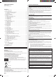
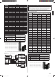
INSTALLATION MANUAL SPECIAL PRECAUTIONS OUTDOOR UNIT PART No. 9380545101-06 When Wiring Contents 1. SAFETY PRECAUTIONS ……………………………………………………………… 1 2. ABOUT THIS PRODUCT ………………………………………………………………… 2 2. 1. Precautions for using R410A refrigerant ………………………………………… 2 2. 2. Special tools for R410A refrigerant ……………………………………………… 2 2. 3. Accessories ………………………………………………………………………… 2 2. 4. System configuration ……………………………………………………………… 3 3. GENERAL SPECIFICATIONS …………………………………………………………… 5 3. 1.
WARNING During the pump down operation, make sure that the compressor is turned off before you remove the refrigerant piping. Do not remove the connection pipe while the compressor is in operation with 2 way or 3 way valve open. This may cause abnormal pressure in the refrigeration cycle that leads to rupture and even injury.
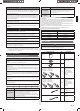
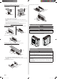
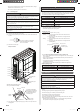
2. 4. System configuration Layout example for the indoor units and outdoor unit Valve cover removal · Remove the six mounting screws. · Remove the valve cover. 2. 4. 1.
A 18,000 18,000 18,000 15,000 15,000 15,000 15,000 15,000 15,000 15,000 15,000 15,000 15,000 15,000 15,000 12,000 12,000 12,000 12,000 12,000 12,000 12,000 12,000 12,000 12,000 12,000 12,000 9,000 9,000 9,000 9,000 9,000 7,000 102 103 104 105 106 107 108 109 110 111 112 113 114 115 116 117 118 119 120 121 122 123 124 125 126 127 128 129 130 131 132 133 134 B 9,000 9,000 7,000 15,000 15,000 12,000 12,000 12,000 12,000 12,000 9,000 9,000 9,000 9,000 7,000 12,000 12,000 12,000 12,000 12,000 12,000 12,000 9,0
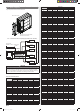
2. 4. 3. Limitation of refrigerant piping length CAUTION Circuit breaker The total maximum pipe lengths and height difference of this product are shown in the table. If the units are further apart than this, correct operation cannot be guaranteed. Total max. length *1) 45 model (a+b+c+d+e) 262 ft. (80 m) 36 model (a+b+c+d) 229 ft. (70 m) 45 model (a, b, c, d or e) Max.
3. 6. Additional charging CAUTION Refrigerant suitable for a total piping length of 164 ft. (50 m) is charged in the outdoor unit at the factory. When the piping is longer than 164 ft. (50 m), additional charging is necessary. For the additional amount, see the table below. Total piping length [ft. (m)] Additional 45 model refrigerant charge 36 model 164 (50) or less 197 (60) 230 (70) 264 (80) None 7 oz. (200 g) 14 oz. (400 g) 1 lbs. 5 oz. (600 g) None 7 oz. (200 g) 14 oz. (400 g) — 0.21 oz./ft.
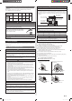
When there is an obstruction in the upper space: [Unit: in. (mm)] (1) When there are obstacles at the rear and above. (2) Multiple parallel unit arrangement (2) When there are obstacles at the rear, sides, and above. Max. 20 (500) Max. 20 (500) 10 10 40 (1000) or more 40 (1000) or more (25 0) (25 0) or or mo re mo 20 (500) or more 138 (3500) or more re 24 (600) or more 60 (1500) or more 12 (300) or more 8 (200) or more 20 (500) or more 10 (250) or more 4. 2. 2.
5-1/2 (140) 8-15/16 (227) Drain pipe mounting hole × 1 CAUTION Do not install directly on the ground, this may result in equipment failure. Make sure the height of the base is 2 in. (50 mm) from the ground. Otherwise, there is a risk that the drainage water will freeze between the device and the surface, disabling drainage. In places where the outdoor temperature drops to 32 °F (0 °C) or lower, the drain water may freeze and may stop up the drain or cause other outdoor unit trouble.
• When pipes are repeatedly bent or stretched, the material will harden, making it difficult to bend or stretch them any more. • Do not bend or stretch the pipes more than 3 times. 5. 1. 3. Connecting pipes CAUTION Be sure to install the pipe against the port on the indoor unit and the outdoor unit correctly. If the centering is improper, the flare nut cannot be tightened smoothly. If the flare nut is forced to turn, the threads will be damaged.
If a leakage is found, immediately repair it and perform a sealing test again. * Decrease the pressure of nitrogen gas before blazing After completing the sealing test, release the nitrogen gas from both valves. Release the nitrogen gas slowly. 6. ELECTRICAL WIRING WARNING Wiring connections must be performed by a qualified person in accordance with specifications. The rated supply of this product is 60Hz, 208/230V. Use a voltage within the range of 187-253V. 5. 3.
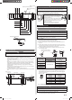
6. 2. Connection diagrams 45 model OUTDOOR UNIT INDOOR UNIT ) n. i /16 m 0m (3 TERMINAL 1-3 Earth wire 50 n.( i /16 m) 1 2 3 G Power supply cable and connection cable m -15 1 INDOOR UNIT B 1 2 3 G Caution when wiring cable (1) Use ring type terminals with insulating sleeves as shown in the figure to connect to the terminal block. (2) Securely clamp the ring type terminals to the wires using an appropriate tool so that the wires do not come loose.
WARNING Disconnect switch for over current protection given in the table below is to be installed between the indoor unit and the outdoor unit. (3) Fasten the power supply cable and the connection cable to the conduit holder using the lock nut. (Open the knock out holes with the tool so as not to transform conduit plate if necessary.) Disconnect switch 15A Cable tie with clip [Large] (Accessories) CAUTION Be sure to refer the preceding diagram and do the correct field wiring.
6. 4. Connecting the Central remote controller (Option) 7. HOW TO OPERATE DISPLAY UNIT (1) When connecting the Central remote controller (Option), please use the outdoor unit side knockout hole (Ø22.2 mm diameter). • Please ensure that there are no gaps in the Knockout hole. 7. 1. Various setting methods WARNING Never touch electrical components such as the terminal blocks or reactor except the switch on the display board. It may cause a serious accident such as electric shock.
Switch SW1 Push Function or operation method Factory setting • For the test run start and stop. ― • For the pump down start and stop. SW2 Push • For when check run function is activated. ― • For displaying the check run. SET1-1 DIP • For selecting cooling or heating during test operation. SET1-2 DIP • For switching SW1 operation. OFF SET1-3 DIP • For switching the base heater.
8. 3. Operating procedure for check run CAUTION Initiate check run after more than 12 hours after the power source is connected. NOTE: Be sure that the indoor unit and outdoor unit are not operating before starting the check run. (1) Press the "CHECK" switch for 3 seconds or more. CHECK SW2 (2) The number of indoor units (and the places) connected through the communication lines is displayed.
[How to record the contents] • Please fill the displayed results according to the following example. Example 1) When piping A to D is connected but the wires for B and C are connected in reverse. The LEDs will light up in 7 second intervals in the following order. POWER ERROR MODE MONITOR A B C D E F (7 sec.) Blink (2 times) (7 sec.) (7 sec.) (7 sec.) (a) Please write a ● where the LEDs light up in the order that they light up.
9. TEST RUN 8. 4. Check run judgment failure display • If check run cannot be performed, the following is displayed. In this case, the check run will stop. Please check by using the cooling test run of the indoor unit. 8. 4. 1. Temperature out of range judgment POWER ERROR MODE (1) Indoor unit MONITOR A B C CAUTION Always connect the power supply 12 hours prior to the start of the operation in order to protect the compressor.
10. ERROR CODE Error code • If an error occurs, the LED will light up to display the error location and the error code. 10. 1. In the event of an error • The error LED flashes quickly. POWER ERROR MODE MONITOR A B C D E F Blink (High-speed) 10. 2. Error location display • LEDs A to F of MONITOR light up and display the error location. In the case of an overall error, LEDs A to F of MONITOR do not light up. POWER ERROR MODE MONITOR A B C D E F Blink (High-speed) 10. 3.
(3) To start operation, press the [PUMP DOWN] switch*2 for 3 seconds or press after the power has been on for 3 min. TEST RUN *2: Push switch (SW1) SW1 PUMP DOWN During pump down, the LED (POWER/MODE) will flash 3 times consecutively. POWER ERROR MODE MONITOR A B C D E F Blink (3 times) NOTE: If the [PUMP DOWN] switch is pressed during compressor operation, the compressor will stop, and the operation will start after about 3 min. (4) Close the liquid pipe valve. (5) When 7.3 psi ~ 0 psi (0.