
AOU45RLXFZ Installation Manual


En-9
• When pipes are repeatedly bent or stretched, the material will harden, making it
diffi cult to bend or stretch them any more.
• Do not bend or stretch the pipes more than 3 times.
5. 1. 3. Connecting pipes
CAUTION
Be sure to install the pipe against the port on the indoor unit and the outdoor unit
correctly. If the centering is improper, the flare nut cannot be tightened smoothly.
If the fl are nut is forced to turn, the threads will be damaged.
Do not remove the fl are nut from the outdoor unit pipe until immediately before con-
necting the connection pipe.
After installing the piping, make sure that the connection pipes do not touch the com-
pressor or outer panel. If the pipes touch the compressor or outer panel, they will
vibrate and produce noise.
If there are a large number of fl are connections due to the number of indoor units con-
nected, please confi rm that the valves that are not connected are closed.
Not doing so may cause a refrigerant leak.
When connecting the indoor unit, it should be connected in the order of port A, B, C,
and so on. Please be sure to close remaining unconnected ports so that they do not
leak refrigerant.
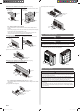
(1) Detach the caps and plugs from the pipes.
(2) Center the pipe against the port on the outdoor unit, and then turn the fl are nut
by hand.
To prevent gas leakage, coat the fl are
surface with alkylbenzene oil (HAB).
Do not use mineral oil.
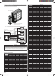
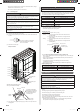
(3) Attach the connection pipe.
Example: 45 model
Connection pipe
(Liquid)
Connection pipe
(Gas)
Flare nut
Valve (Liquid)
Valve (Gas)
Port A
Port B
Port C
Port D
Port E
Holding
wrench
Insulation of the
connection pipe
Torque wrench
Body side
Flare nut
With this model, the Holding wrench
can only be inserted horizontally.
To prevent condensation
from dropping, insulate the
gap between the fl are nut
and the insulation of the
connection pipe.
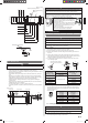
(4) When the fl are nut is tightened properly by your hand, use a torque wrench to
fi nally tighten it
CAUTION
Hold the torque wrench at its grip, keeping it in a right angle with the pipe, in order to
tighten the fl are nut correctly.
• Outer panel may be distorted if fastened only with a wrench. Be sure to fi x the
elementary part with a holding wrench and fasten with a torque wrench (refer to below
diagram). Do not apply force to the blank cap of the valve or hang a wrench, etc., on the
cap. If blank cap is broken, it may cause leakage of refrig
erant.
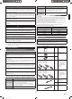
Flare nut [in. (mm)] Tightening torque [lbf·ft. (N·m)]
1/4 (6.35) dia. 11.8 to 13.3 (16 to 18)
3/8 (9.52) dia. 23.6 to 31.0 (32 to 42)
1/2 (12.70) dia. 36.1 to 45.0 (49 to 61)
5/8 (15.88) dia. 46.5 to 55.3 (63 to 75)
3/4 (19.05) dia. 66.4 to 81.1 (90 to 110)
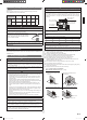
5. 1. 4. Handling precautions for the valves
• Mounted part of Blank cap is sealed for protection.
• Fasten blank cap tightly after opening valves.
Operating the valves
• Use a hexagon wrench [size: 3/16 in. (4 mm)].
• Opening (1) Insert the hexagon wrench into the valve shaft, and turn it
counterclockwise.
(2) Stop turning when the valve shaft can no longer be turned.
(Open position)
• Closing (1) Insert the hexagon wrench into the valve shaft, and turn it
clockwise.
(2) Stop turning when the valve shaft can no longer be turned.
(Closed position)
Opening direction
Hexagon wrench
Seal (blank cap
installation portion)
Liquid pipe
Gas pipe
Opening direction
5. 1. 5. How to use adapter (Connection ports of outdoor unit)
• When using the ADAPTER, be careful not to overtighten the nut, or the smaller pipe
may be damaged.
• Apply a coat of refrigeration oil to the threaded connection port of the outdoor unit
where the fl are nut comes in.
• Use appropriate wrenches to avoid damaging the connection thread by
overtightening the fl are nut.
• Apply wrenches on both of fl are nut (local part), and ADAPTER to tighten them.
Adapter tightening torque
Adapter type [in. (mm)] Tightening torque [lbf·ft. (N·m)]
ø1/2 (ø12.70) → ø3/8 (ø9.52) 36.1 to 45.0 (49 to 61)
ø1/2 (ø12.70) → ø5/8 (ø15.88) 36.1 to 45.0 (49 to 61)
5. 2. Sealing test
CAUTION
Use only nitrogen gas.
Never use refrigerant gas, oxygen, in fl ammable gas or poisonous gas to pressurize
the system. (If oxygen is used, there is the danger of an explosion.)
Do not apply shock during sealing test.
It can rupture the pipes and cause serious injury.
Do not turn on the power unless all operations are complete.
Do not block the walls and the ceiling until the sealing test and the charging of the
refrigerant gas have been completed.
After connecting the pipes, perform an sealing test.
Recheck that the 3-way valve are closed before performing a sealing test.
(Fig. B)
Pour nitrogen gas through both the liquid pipe and the gas pipe.
Pressurize nitrogen gas to 4.2 MPa to perform the sealing test.
Check all fl are connection areas and brazed areas.
Then, check that the pressure has not decreased.
Compare the pressures after pressurizing and letting it stand for 24 hours, and check
that the pressure has not decreased.
* When the outdoor temperature changes 5 °C, the test pressure changes 0.05 MPa.
If the pressure has dropped, the pipe joints may be leaking.
9380545101-06_IM_3L.indb 99380545101-06_IM_3L.indb 9 2018/6/20 14:01:522018/6/20 14:01:52