
AOU45RLXFZ Installation Manual


En-1
1. SAFETY PRECAUTIONS
This installation manual describes how to install the outdoor unit only. To install the indoor
unit, refer to the installation manual included with the indoor unit.
IMPORTANT!
Please Read Before Starting
This air conditioning system meets strict safety and operating standards.
As the installer or service person, it is an important part of your job to install or service the
system so it operates safely and effi ciently.
For safe installation and trouble-free operation, you must:
• Carefully read this instruction booklet before beginning.
• Follow each installation or repair step exactly as shown.
• Observe all local, state, and national electrical codes.
• Pay close attention to all warning, and caution notices given in this manual.
WARNING:
This symbol refers to a hazard or unsafe practice which can result in
severe personal injury or death.
CAUTION:
This symbol refers to a hazard or unsafe practice which can result in
personal injury and the potential for product or property damage.
• Hazard alerting symbols
Electrical
Safety / alert
If Necessary, Get Help
These instructions are all you need for most installation sites and maintenance conditions.
If you require help for a special problem, contact our sales/service outlet or your certifi ed
dealer for additional instructions.
In Case of Improper Installation
The manufacturer shall in no way be responsible for improper installation or maintenance
service, including failure to follow the instructions in this document.
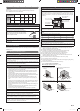
SPECIAL PRECAUTIONS
When Wiring
ELECTRICAL SHOCK CAN CAUSE SEVERE PERSONAL INJURY OR DEATH. ONLY
A QUALIFIED, EXPERIENCED ELECTRICIAN SHOULD ATTEMPT TO WIRE THIS
SYSTEM.
• Do not supply power to the unit until all wiring and tubing are completed or reconnected
and checked.
• Highly dangerous electrical voltages are used in this system. Carefully refer to the wiring
diagram and these instructions when wiring. Improper connections and inadequate
earthing (grounding) can cause accidental injury or death.
• Earth (Ground) the unit following local electrical codes.
• Connect all wiring tightly. Loose wiring may cause overheating at connection points and
a possible fi re hazard.
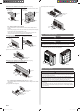
When Transporting
Be careful when picking up and moving the indoor and outdoor units. Get a partner to
help, and bend your knees when lifting to reduce strain on your back. Sharp edges or thin
aluminum fi ns on the air conditioner can cut your fi ngers.
When Installing...
...In a Ceiling or Wall
Make sure the ceiling/wall is strong enough to hold the unit’s weight. It may be necessary
to construct a strong wood or metal frame to provide added support.
...In a Room
Properly insulate any tubing run inside a room to prevent “sweating” that can cause
dripping and water damage to walls and fl oors.
...In Moist or Uneven Locations
Use a raised concrete pad or concrete blocks to provide a solid, level foundation for the
outdoor unit. This prevents water damage and abnormal vibration.
...In an Area with High Winds
Securely anchor the outdoor unit down with bolts and a metal frame. Provide a suitable air
baffl e.
...In a Snowy Area (for Heat Pump-type Systems)
Install the outdoor unit on a raised platform that is higher than drifting snow. Provide snow
vents.
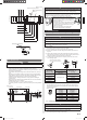
When Connecting Refrigerant Tubing
• Keep all tubing runs as short as possible.
• Use the fl are method for connecting tubing.
• Apply refrigeration compressor oil (or equivalent) used for the outdoor unit to the matching
surfaces of the fl are and union tubes before connecting them, then tighten the nut with a
torque wrench for a leak-free connection.
• Check carefully for leaks before opening the refrigerant valves.
NOTE:
Depending on the system type, liquid and gas lines may be either narrow or wide.
Therefore, to avoid confusion the refrigerant tubing for your particular model is specifi ed
as either “small” or “large” rather than as “liquid” or “gas”.
When Servicing
•Turn the power OFF at the main circuit breaker panel before opening the unit to check or
repair electrical parts and wiring.
• Keep your fi ngers and clothing away from any moving parts.
• Clean up the site after you fi nish, remembering to check that no metal scraps or bits of
wiring have been left inside the unit being serviced.
• After installation, explain correct operation to the customer, using the operating manual.
• Be sure to read this Manual thoroughly before installation.
• The warnings and precautions indicated in this Manual contain important information
pertaining to your safety. Be sure to observe them.
• Hand this Manual, together with the Operating Manual, to the customer. Request the
customer to keep them on hand for future use, such as for relocating or repairing the
unit.
WARNING
Never touch electrical components immediately after the power supply has been
turned off. Electrical shock may occur. After turning off the power, always wait 10
minutes or more before touching electrical components.
If refrigerant leaks while work is being carried out, ventilate the area. If the refrigerant
comes in contact with a fl ame, it produces a toxic gas.
During installation, make sure that the refrigerant pipe is attached fi rmly before you
run the compressor. Do not operate the compressor under the condition of refrigerant
piping not attached properly with 2-way or 3-way valve open. This may cause abnor-
mal pressure in the refrigeration cycle that leads to breakage and even injury.
When installing and relocating the air conditioner, do not mix gases other than the
specifi ed refrigerant (R410A) to enter the refrigerant cycle. If air or other gas enters
the refrigerant cycle, the pressure inside the cycle will rise to an abnormally high value
and cause breakage, injury, etc.
Do not modify power cable, use extension cable or branch wiring. Improper use may
cause electric shock or fi re by poor connection, insuffi cient insulation or over current.
Do not purge the air with refrigerants but use a vacuum pump to vacuum the installa-
tion.
There is not extra refrigerant in the outdoor unit for air purging.
Using the same vacuum pump for different refrigerants may damage the vacuum
pump or the unit.
Use a clean gauge manifold, vacuum pump and charging hose for R410A exclusively.
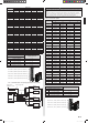
Contents
1. SAFETY PRECAUTIONS ……………………………………………………………… 1
2. ABOUT THIS PRODUCT ………………………………………………………………… 2
2. 1. Precautions for using R410A refrigerant ………………………………………… 2
2. 2. Special tools for R410A refrigerant ……………………………………………… 2
2. 3. Accessories ………………………………………………………………………… 2
2. 4. System confi guration ……………………………………………………………… 3
3. GENERAL SPECIFICATIONS …………………………………………………………… 5
3. 1. Power ………………………………………………………………………………… 5
3. 2. Selecting circuit breaker and wiring ……………………………………………… 5
3. 3. Selecting the pipe material ………………………………………………………… 5
3. 4. Installing insulation ………………………………………………………………… 5
3. 5. Operating range …………………………………………………………………… 5
3. 6. Additional charging ………………………………………………………………… 6
4. INSTALLATION WORK ………………………………………………………………… 6
4. 1. Selecting an installation location ………………………………………………… 6
4. 2. Installation dimensions …………………………………………………………… 6
4. 3. Placing the unit ……………………………………………………………………… 7
4. 4. Drain installation …………………………………………………………………… 7
4. 5. Secure the unit ……………………………………………………………………… 8
5. PIPE INSTALLATION …………………………………………………………………… 8
5. 1. Pipe connection …………………………………………………………………… 8
5. 2. Sealing test ………………………………………………………………………… 9
5. 3. Vacuum process ………………………………………………………………… 10
6. ELECTRICAL WIRING ………………………………………………………………… 10
6. 1. Notes for electrical wiring ……………………………………………………… 11
6. 2. Connection diagrams …………………………………………………………… 11
6. 3. Wiring method …………………………………………………………………… 12
6. 4. Connecting the Central remote controller (Option) …………………………… 13
7. HOW TO OPERATE DISPLAY UNIT ………………………………………………… 13
7. 1. Various setting methods ………………………………………………………… 13
7. 2. Base heater forced off function ………………………………………………… 14
7. 3. Outdoor unit low noise operation function (option) …………………………… 14
8. CHECK RUN …………………………………………………………………………… 14
8. 1. Things to confi rm before starting the check run. ……………………………… 14
8. 2. Restrictions applicable when performing the check run ……………………… 14
8. 3. Operating procedure for check run …………………………………………… 15
8. 4. Check run judgment failure display …………………………………………… 17
8. 5. Re-display check run results …………………………………………………… 17
8. 6. Automatic wiring correction memory reset …………………………………… 17
9. TEST RUN ……………………………………………………………………………… 17
9. 1. TEST RUN method ……………………………………………………………… 17
10. ERROR CODE ………………………………………………………………………… 18
10. 1. In the event of an error ……………………………………………………… 18
10. 2. Error location display ……………………………………………………… 18
10. 3. Error code display …………………………………………………………… 18
11. PUMP DOWN…………………………………………………………………………… 18
12. CUSTOMER GUIDANCE ……………………………………………………………… 19
INSTALLATION MANUAL
OUTDOOR UNIT
PART No. 9380545101-06
9380545101-06_IM_3L.indb 19380545101-06_IM_3L.indb 1 2018/6/20 14:01:522018/6/20 14:01:52