
AOU45RLXFZ Installation Manual


En-5
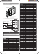
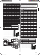
2. 4. 3. Limitation of refrigerant piping length
CAUTION
The total maximum pipe lengths and height difference of this product are shown in the
table.
If the units are further apart than this, correct operation cannot be guaranteed.
Total max. length *1)
45 model (a+b+c+d+e) 262 ft. (80 m)
36 model (a+b+c+d) 229 ft. (70 m)
Max. length for each indoor unit
45 model (a, b, c, d or e)
82 ft. (25 m)
36 model (a, b, c or d)
"Max. height difference between
outdoor unit and each indoor unit"
(H1) 49 ft. (15 m)
"Max. height difference between indoor
units"
(H2) 32 ft. (10 m)
Min. length for each indoor unit
45 model (a, b, c, d or e)
17 ft. (5 m)
36 model (a, b, c or d)
Total min. length
(a+b) 50 ft. (15 m)
)
*1) If the total piping is longer than 164 ft. (50 m), additional refrigerant charging is neces-
sary. (For more information, refer to “3.6. Additional charging”.)
3. GENERAL SPECIFICATIONS
3. 1. Power
WARNING
The rated voltage of this product is 208/230 V A.C. 60 Hz.
Before turning on verify that the voltage is within the 187 V to 264 V range.
Always use a special branch circuit and install a special receptacle to supply power to
the air conditioner.
Use a special branch circuit breaker and receptacle matched to the capacity of the air
conditioner. (Install in accordance with standard.)
Do not extend the power cord.
Perform wiring work in accordance with standards so that the air conditioner can be
operated safely and positively.
Install a leakage special branch circuit breaker in accordance with the related laws
and regulations and electric company standards.
CAUTION
The power source capacity must be the sum of the air conditioner current and the
current of other electrical appliances. When the current contracted capacity is insuf-
fi cient, change the contracted capacity.
When the voltage is low and it is diffi cult to start the air conditioner, contact the power
company to have the voltage raised.
3. 2. Selecting circuit breaker and wiring
CAUTION
Be sure to install a breaker of the specifi ed capacity.
Regulation of cables and breaker differs from each locality, refer in accordance with
local rules.
Voltage rating
1ø 208/230V (60Hz)
Operating range
187-264V
Cable Conduit cable size
*1)
Remarks
Power supply cable
45 model: 10 AWG
2 cable + Ground, 1 ø 208/230V
36 model: 8 AWG
Connection cable 14AWG 3 cable + Ground, 1 ø 208/230V
Remote controller cable
*2)
22AWG (0.33 mm²)
Use shield cable in accordance
with local rules for cable. (Polar
3 core)
*1) Selected sample: Select the correct cable type and size according to the country or
region’s regulations.
Max. wire length: Set a length so that the voltage drop is less than 2%. Increase the
wire diameter when the wire length is long.
*2) The remote controller cable supplied with the Central remote controller is for indoor
use. If you require cables for outdoor use, please purchase locally. Material is not spec-
ifi ed. However, it should be selected considering the operating environment (tempera-
ture, humidity), and regional regulations (ROHS Directive, etc.).
Breaker Specifi cation
*3)
Circuit breaker
45 model Current : 30(A)
36 model Current : 40(A)
Earth leakage breaker Leakage current : 30mA 0.1sec or less
*4)
*3) Select the appropriate breaker of the described specifi cation according to the national
or regional standards.
*4) Select the breaker that enough load current can pass through it.
3. 3. Selecting the pipe material
CAUTION
Do not use existing pipes.
Use pipes that have clean external and internal sides without any contamination which
may cause trouble during use, such as sulphur, oxide, dust, cutting waste, oil, or wa-
ter.
It is necessary to use seamless copper pipes.
Material: Phosphor deoxidized seamless copper pipes.
It is desirable that the amount of residual oil is less than 40 mg/10 m.
Do not use copper pipes that have a collapsed, deformed, or discoloured portion
(especially on the interior surface). Otherwise, the expansion valve or capillary tube
may become blocked with contaminants.
Improper pipe selection will degrade performance. As an air conditioner using R410A
incurs pressure higher than when using conventional refrigerant, it is necessary to
choose adequate materials.
The diameters of the connection pipes differ according to the capacity of the indoor unit.
Refer to the following table for the proper diameters of the connection pipes between the
indoor and outdoor units.
Capacity of indoor
unit
Gas pipe size
(thickness)
in. (in.) [mm (mm)]
Liquid pipe size
(thickness)
in. (in.) [mm (mm)]
7 – 12 ø3/8 (0.032) [ø9.52 (0.8)] ø1/4 (0.032) [ø6.35 (0.8)]
15, 18 ø1/2 (0.032) [ø12.70 (0.8)] ø1/4 (0.032) [ø6.35 (0.8)]
24 ø5/8 (0.039) [ø15.88 (1.0)] ø1/4 (0.032) [ø6.35 (0.8)]
CAUTION
Operation cannot be guaranteed if the correct combination of pipes, valves, etc., is not
used to connect the indoor and outdoor units.
3. 4. Installing insulation
• Determine the thickness of the insulation material by referring to Table A.
Table A, Selection of insulation
(Use an insulation material with equal heat transmission rate or below
0.040 W/(m·k))
Recommended minimum thickness for
heat insulating material (mm)
Relative humidity
70% 75% 80% 85%
Pipe diameter
[in. (mm)]
1/4 (6.35) 8 10 13 17
3/8 (9.52) 9 11 14 18
1/2 (12.70) 10 12 15 19
5/8 (15.88) 10 12 16 20
3/4 (19.05) 10 13 16 21
• When an ambient temperature and relative humidity exceed 89.6 °F [(32 °C) DB] and
85% respectively, please strengthen heat insulation for the refrigerant pipes.
3. 5. Operating range
Model Temperature Indoor air intake Outdoor air intake
45 model
Cooling
Maximum 90 °F(32.2 °C) DB 115 °F(46.1 °C) DB
Minimum 65 °F(18.3 °C) DB 14 °F(-10.0 °C) DB
Heating
Maximum 88 °F(31.1 °C) DB 75 °F(23.8 °C) DB
Minimum 60 °F(15.5 °C) DB 5 °F(-15.0 °C) DB
36 model
Cooling
Maximum 90 °F(32.2 °C) DB 115 °F(46.1 °C) DB
Minimum 65 °F(18.3 °C) DB 14 °F(-10.0 °C) DB
Heating
Maximum 88 °F(31.1 °C) DB 75 °F(23.8 °C) DB
Minimum 60 °F(15.5 °C) DB -15 °F(-26.1 °C) DB
Indoor humidity about 80% or less
9380545101-06_IM_3L.indb 59380545101-06_IM_3L.indb 5 2018/6/20 14:01:522018/6/20 14:01:52