
AOU45RLXFZ Installation Manual


En-8
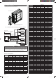
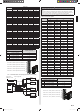
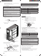
[Unit: in. (mm)]
Drain cap mounting hole × 7
Drain pipe mounting
hole × 1
5-1/2 (140)
8-15/16 (227)
11-5/8 (296)
12 (305)
1-9/16 (40)
12-3/8 (315)
12-5/8 (321)
13-7/16 (341)
1-15/16 (50)
10-15/16 (278)
17-1/4 (438)
3 (76)
20-11/16 (526)
24-1/2 (622)
27-3/16 (690)
Drain pipe mounting hole
Base
Drain pipe
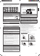
4. 5. Secure the unit
WARNING
When installing the outdoor unit where it may exposed to strong wind, fasten it secure-
ly.
• Please install the outdoor unit without slant. (within 3 degrees )
• Install 4 anchor bolts at the locations indicated with arrows in the fi gure.
• To reduce vibration, do not install the unit directly on the ground. Install it on a secure
base (such as concrete blocks).
• The foundation shall support the legs of the unit and have a width of 2 in. (50 mm) or
more.
• Depending on the installation conditions, the outdoor unit may spread its vibration
during operation, which may cause noise and vibration. Therefore, attach damping
materials (such as damping pads) to the outdoor unit during installation.
• Install the foundation, making sure that there is enough space for installing the
connection pipes.
• Secure the unit to a solid block using foundation bolts. (Use 4 sets of commercially
available M10 bolts, nuts, and washers.)
• The bolts should protrude 1 in. (20 mm). (Refer to the fi gure.)
• If overturning prevention is required, purchase the necessary commercially available
items.
6-9/16 (166)
AIR
25-9/16 (650) 6-1/16 (154)
2 (50) 2 (50)
5/8 (16)
16-1/8 (410)
[Unit: in. (mm)]
Bolt
1 (20)
Nut
Base
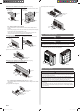
CAUTION
Do not install directly on the ground, this may result in equipment failure. Make sure the
height of the base is 2 in. (50 mm) from the ground. Otherwise, there is a risk that the
drainage water will freeze between the device and the surface, disabling drainage.
In places where the outdoor temperature drops to 32 °F (0 °C) or lower, the drain water
may freeze and may stop up the drain or cause other outdoor unit trouble. Therefore take
measures so that the drain water will not freeze and clog the drain.
2 in. (50 mm)
or more
Please set up the outdoor unit in a high place and
please do not arrange the frame of installed stand
under the drain port, because the water dropped from
the drain port repeats freezing and accumulating, and
may block the drain port.
In areas with heavy snowfall , where intake and outlet
of the outdoor unit can become blocked by snow. It is
recommended that unit be installed under a canopy or
elevated on a high stand.
Failure to do so will result in poor heating perfor-
mance and/or premature failure of equipment.
5. PIPE INSTALLATION
5. 1. Flare connection (pipe connection)
CAUTION
Do not use mineral oil on a fl ared part. Prevent mineral oil from getting into the system
as this would reduce the lifetime of the units.
While welding the pipes, be sure to blow dry nitrogen gas through them.
The maximum lengths of this product are shown in the table. If the units are further
apart than this, correct operation cannot be guaranteed.
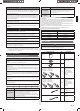
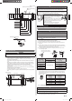
5. 1. 1. Flaring
• Use special pipe cutter and fl are tool exclusive for R410A.
(1) Cut the connection pipe to the necessary length with a pipe cutter.
(2) Hold the pipe downward so that the cuttings will not enter the pipe and remove
any burrs.
(3) Insert the fl are nut (always use the fl are nut attached to the indoor and outdoor
units respectively) onto the pipe and perform the fl are processing with a fl are tool.
Leakage of refrigerant may result if other fl are nuts are used.
(4) Protect the pipes by pinching them or with tape to prevent dust, dirt, or water
from entering the pipes.
L
Check if [L] is fl ared uniformly
and is not cracked or scratched.
Pipe
A
B
Die
Pipe outside
diameter [in. (mm)]
Dimension A [in. (mm)]
Dimension B
0
- 0.4
[in. (mm)]
Flare tool for R410A,
clutch type
1/4 (6.35)
0 to 0.020 (0 to 0.5)
3/8 (9.1)
3/8 (9.52) 1/2 (13.2)
1/2 (12.70) 5/8 (16.6)
5/8 (15.88) 3/4 (19.7)
3/4 (19.05) 15/16 (24.0)
• When using conventional fl are tools to fl are R410A pipes, the dimension A should
be approximately 0.020 in. (0.5 mm) more than indicated in the table (for fl aring
with R410A fl are tools) to achieve the specifi ed fl aring. Use a thickness gauge to
measure the dimension A.
Pipe outside
diameter
[in. (mm)]
Width across fl ats
of Flare nut
[in. (mm)]
1/4 (6.35) 11/16 (17)
3/8 (9.52) 7/8 (22)
1/2 (12.70) 1 (26)
5/8( 15.88) 1-1/8 (29)
3/4 (19.05) 1-7/16 (36)
Width across fl ats
5. 1. 2. Bending pipes
CAUTION
To prevent breaking of the pipe, avoid sharp bends. Bend the pipe with a radius of
curvature of 4 in. (100 mm) or more.
If the pipe is bent repeatedly at the same place, it will break.
• If pipes are shaped by hand, be careful not to collapse them.
• Do not bend the pipes at an angle of more than 90°.
9380545101-06_IM_3L.indb 89380545101-06_IM_3L.indb 8 2018/6/20 14:01:522018/6/20 14:01:52