P3PC-E177-03EN fi-4860C Image Scanner Installation Guide
INTRODUCTION Thank you for purchasing the fi-4860C Duplex Color Scanner. The fi-4860C is an image scanner designed to scan documents in large quantities. The fi-4860C has the following features. High speed, high quality color scanning capabilities Scans documents of Letter and A4 size at the speed of 60ppm/120ipm @200dpi. Highly reliable document handling Accepts various thicknesses, sizes and types of documents.
The contents of the Operator’s Guide is as follows: 1. BASIC SCANNER OPERATIONS This chapter describes basic scanner operations including basic document scanning. 2. SCANNING VARIOUS TYPES OF DOCUMENTS This chapter describes how to scan various type of documents. 3. DAILY CARE This chapter describes how to clean the scanner. 4. REPLACEMENT OF CONSUMABLES This chapter describes how to replace scanner consumables. 5.
■ Regulatory Information FCC declaration This equipment has been tested and found to comply with the limits for a Class A digital device, pursuant to Part 15 of the FCC Rules. These limits are designed to provide reasonable protection against harmful interference when the equipment is operated in a commercial environment.
Bescheimigung des Herstellers / Importeurs Hiermit wird bescheinigt, daß der/dieldas •fi-4860C in Übereinsstimmung mit den Bestimmungen der •AmtsblVfg 243/1991 funkentstört ist. Der Deutschen Bundesport wurde das Inverkehrbringen dieses Gerätes angezeigt und die Berechtigung zur Überprüfung der Serie auf Einhaltung der Bestimmungen eingeräumt. •Maschinenlärminformationsverordnung 3. GS GV, 18.01.1991:Der höchste Schalldruckpegel beträgt 70 dB (A) order weniger gemäß ISO/7779.
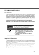
International ENERGY STAR® Program As an ENERGY STAR® Partner, PFU LIMITED has determined that this product meets the ENERGY STAR® guidelines for energy efficiency. The International ENERGY STAR® Office Equipment Program is an international program that promotes energy saving through the penetration of energy efficient computers and other office equipment. The program backs the development and dissemination of products with functions that effectively reduce energy consumption.
About the use of mercury The scanner lamp contains mercury. Too avoid unexpected injury, read the followings carefully. Doing following actions may result in serious personal injuries: •Do not put the substance in the lamp in your mouth as it contains mercury. •Do not incinerate, crush, or shred the scanner. •Do not breath the chemical liquid contained in the scanner parts. Disposing of the scanner should be conducted as required by local ordinances or regulations.
Trademarks Microsoft, Windows and Windows NT are registered trademarks of Microsoft Corporation of the USA and other respective countries. ISIS is a registered trademark of Pixel Translations, A Division of Actionpoint Inc. Adobe and the Adobe logo as well as Acrobat and the Acrobat Logo are trademarks of Adobe Systems Incorporated. Other product names referred to in this manual are registered trademarks or trademarks of respective companies.
■ Note, Liability READ ALL OF THIS MANUAL CAREFULLY BEFORE USING THIS PRODUCT. IF NOT USED CORRECTLY, UNEXPECTED INJURY MAY BE CAUSED TO USERS OR BYSTANDERS.
■ Preface Safety Precautions This manual describes important details for ensuring the safe and correct use of this product. Thoroughly read this manual before you start to use this product. In particular, be sure to read and fully understand the Safety Precautions described in this manual before you use this product. Also, store this manual in a safe place so that it can be easily referred to during use of this product.
Symbols Used In This Manual This manual uses the following symbols in explanations in addition to warning indications. ATTENTION This symbol alerts operators to particularly important information. Be sure to read this information. This symbol alerts operators to helpful advice regarding operation. HINT A TRIANGLE symbol indicates that special care and attention is required. The drawing inside the triangle shows the specific caution.
Screen Examples In This Manual The screen examples in this manual are subject to change without notice in the interest of product improvement. If the actual displayed screen differs from the screen examples in this manual, operate by following the actual displayed screen referring to the User's Manual of the scanner application you are using.
■ Safety Precautions WARNING The following describes important warnings described in this manual. Do not touch the AC cable with wet hands. Do not insert or disconnect the power plug with wet hands. Doing so might cause electric shock. Do not damage the AC cable. A damaged AC cable may cause fire or electric shock. Do not place heavy objects on AC cables, or pull, bend, twist, heat, damage or modify AC cables.
Use this scanner only at the indicated power voltage. Do not connect to multiple-power strips. Use this scanner only at the indicated power voltage and current. Improper power voltage and current might cause fire or electric shock. Also, do not connect to multiple-power strips. Wipe any dust from the power plug. Wipe off any dust from metal parts on the power plug or metal fittings with a soft, dry cloth. Accumulated dust might cause fire or electric shock.
Do not put liquids inside the scanner. Do not insert or drop metal objects in to the scanner. Do not scan wet documents or document with paper clips or staples. Do not splash or allow the scanner to get wet. If foreign objects (water, small metal objects, liquids, etc.) get inside the scanner, immediately turn off the scanner and disconnect the power plug from the power outlet. Then contact the agent where you bought the scanner or Maintenance Service Center.
Do not touch the inside of the scanner unless necessary. Do not take apart or modify the scanner. The inside of the scanner contains high-voltage components. Touching these components might cause fire or electric shock. CAUTION The following describes important cautions described in this manual. Do not install the scanner on unstable surfaces. Install the scanner on a desk so that none of its parts protrude outside of the desktop. Also, make sure that the scanner is installed on a flat, level surface.
Do not block the ventilation ports. Do not block the ventilation ports. Blocking the ventilation ports generates heat inside of scanner, that may results in fire or scanner failure. Do not place heavy objects or climb on top of the scanner. Do not place heavy objects on the scanner or use the scanner's top surface for performing other work. Improper installation might cause injuries. Before moving the scanner, disconnect the power plug from the power outlet.
Do not use aerosol sprays near the scanner. Do not use aerosol sprays to clean the scanner. Aerosol sprays cause dirt and dust to enter the scanner, resulting scanner failure and malfunction. Avoid any contact when scanner is in use. Avoid any contact when scanner is operating as this may cause injuries. Disconnect the power plug from the power outlet when the scanner is not used for a long period of time.
■ Fujitsu Group Offices Please send your comments on this manual or on Fujitsu products to the following addresses: FUJITSU CANADA, INC. FUJITSU COMPUTER PRODUCTS OF AMERICA, INC. 2904 Orchard Parkway, San Jose, CA 951342009, U.S.A. Phone: (1-800)591-5924; (1-408)432-6333 Technical Assistance Center: (1-800)626-4686 Fax: (1-408)894-1709 Website: http://www.fcpa.com/ E-mail: info@fcpa.fujitsu.
FUJITSU TAIWAN LTD. 19th Fl., No39, Sec.1,Chung-hwa Rd., Taipei, Taiwan Phone: (886-2)2311-2255 Fax: (886-2)2311-2277 Website: http://tw.fujitsu.com/ FUJITSU HONG KONG LTD. 10/F., Lincoln House, 979 King's Road, Taikoo Place, Island East, Hong Kong Phone: (852)2827-5780 Fax: (852)2827-4724 Website: http://hk.fujitsu.com/ E-mail: scanner@fujitsu.com.hk FUJITSU SYSTEMS BUSINESS (THAILAND) LTD. 12th Fl.
●xx
CONTENTS 1 SCANNER BASICS...................................... 1 Checking the Contents of the Scanner Package ...............................2 Names and Functions of Parts ..........................................................3 Operator Panel ..................................................................................6 2 INSTALLATION AND CONNECTIONS ..... 11 Installing the Scanner ......................................................................12 Connecting the Scanner ..................
●xxii
1 SCANNER BASICS This chapter describes how to prepare the scanner before use. 1.1 Checking the Contents of the Scanner Package................2 1.2 Names and Functions of Parts.............................................3 1.3 Operator Panel.......................................................................
1.1 Checking the Contents of the Scanner Package When you unpack the scanner package, make sure that all the following parts are included in the package. If any parts are missing or defective, contact to the distributer where you purchased the scanner from. Please handle the scanner and the accessories with care. Scanner and Accessories Scanner Power cable (x1) FUJITSU TWAIN32 Scanner driver (CD-ROM) FUJITSU ISIS driver (CD-ROM) User Manual (CD-ROM) Adobe® Acrobat® 5.
1.2 Names and Functions of Parts This section describes the names of parts and their functions. ■ Units 1 SCANNER BASICS 1.
No. 4 Name Function 1 Operator panel Used for operating the scanner. 2 Power button Used to power the scanner on/off. 3 Hopper Document input tray. 4 Side guides Used for adjusting the document width. 5 Hopper extension Used for long documents. 6 ADF (Automatic document feeder) Feeds documents automatically. 7 Pick roller unit Picks top page from document stack. 8 Guide plate The pad assy is mounted on. 9 Pad Assy Separates top page from document stack.
■ Assemblies 1 SCANNER BASICS Lamp unit Removable glass sheetguide Lamp socket cover Lamp PAD Assy Lamp Lamp socket cover Guide plate Brake roller unit Pick roller unit 1.
1.3 Operator Panel The operator panel is located at the Upper right hand side of the scanner. The panel consists of an LCD display (16 characters x 2 line), LEDs, and buttons. ■ Arrangement Power button 6 1.
■ Function of Buttons Button Name Function Turns on/off when the main line switch is set to “I”. Send to/Start 1 Starts scanning in test mode. Clears the error if this button is pushed while the Check lamp is on or is blinking. Enter Used for setup, or test mode. Exit Previous SCANNER BASICS Stop Used for setup, or test mode. Returns LCD display to “Ready” status. Used for setup, or test mode. Displays the previous menu item when this button is pushed. Used for setup, or test mode.
■ Function of LEDs LED Power Function Lights when the power supply is switched on. (Green) Read Light during scanning. (Green) Check Lights when a hardware alarm is detected. Lights out when button is pushed. (except initial errors) (Yellow) Blinks when an equipment error occurs. Papaer jam or Double feed is detected. Press [Stop] button to clear the error, and the LED lights out.
■ Counter display Batch counter and Abrasion counters are shown bellow: Batch counter L R e a d x y x x x x x x x x x x 1 Abrasion counter K Fig.1 SCANNER BASICS Simultaneously press the both (Left) and (Right) button for at least one second, to switch to the Life counter panel display as shown bellow: Batch counter L R e a d y * x x x x x x x x x x x x x Life counter K Fig.2 To return from “Fig.2” to “Fig.1”, press the both one second.
Counter Batch counter Functions (Left) button is pressed for at least one second. The number of scanned documents from the start of reading until "Paper empty" or an error is detected. The counter is automatically reset at the start of reading. This counter can be used for checking the number of scanned documents per batch. (Right)button is pressed for at least one second. This counter is increased by one per sheet. The counter is not initialized until the power is turned off.
2 INSTALLATION AND CONNECTIONS This chapter describes how to install and connect the scanner to a PC, and how to install the Fujitsu application software.
2.1 Installing the Scanner The following shows the procedure for installing the scanner. ■ Cautions on placement of scanner 1. Move the scanner to the installing area. Refer to the "Operator’s Guide" stored on the “User Manual (CD-ROM)” about the dimensions of the scanner, and the space required for its installation. ATTENTION ATTENTION 12 Move the scanner with more than two people as it weights approximately 99 lbs (45 Kg). When you moved scanner grab it at the bottom. 2.
2.2 Connecting the Scanner ■ Connecting the power cable Connect the power cable to the power inlet of the device and to a outlet rated to comply with scanner power requirements. 2 INSTALLATION AND CONNECTIONS ■ Connecting the interface cable An interface cable and a SCSI card are required. Use the following SCSI card to connect to PC.
(1) Use the driver attached to the SCSI card. You can download the driver file for each OS from the following address: For ASC29160 http://www.adaptec.com/worldwide/support/drivers_by_product.html?sess=no &cat=/Product/ASC-29160 For ASC39160 http://www.adaptec.com/worldwide/support/drivers_by_product.html?sess=no &cat=/Product/ASC-39160 (2) Install ASPI version 4.70 or above. (For Windows®95, install the ASPI version 4.60.) You can download the driver from the following address.
(4) For other OS, refer to the following ADAPTEC address to get the necessary update files and revises the driver. For ASC29160 http://www.adaptec.com/worldwide/support/drivers_by_product.html?sess=no &cat=/Product/ASC-29160 For ASC39160 http://www.adaptec.com/worldwide/support/drivers_by_product.html?sess=no &cat=/Product/ASC-39160 ATTENTION When connecting the SCSI interface cable, be sure to first connect the SCSI interface cable then turn on the power of the scanner and the PC.
1. Connect and use the thumbscrews to fix the interface cable into the interface connector of the scanner. (Back side) Interface connecter 2. Connect and fix the other end of the interface cable to the PC. HINT 16 The factory default setting for SCSI ID is “No.5”. If the SCSI ID of another SCSI device is set to the same ID, either change the scanner’s SCSI ID or change the SCSI ID of the other SCSI device. For details on how to change the SCSI ID, refer to the "Chapter 7.
3. Turn on the scanner Press the side of “ | ” on the Main line switch. Power on ! 2 Main line switch (Back side) INSTALLATION AND CONNECTIONS Then press the Power button on the Operator panel. When the power is supplied, the green LED on the Operator panel lights. Power Button 2.
4. Press the power switch on your PC. 18 2.
2.3 Installing the Scanner Driver and Application To enable scanning of documents on the scanner, the Scanner driver (FUJITSU TWAIN32 scanner driver) and Image Capturing Software Utilities “ScandAll 21” (ScandAll 21) or other scanning package must be installed on your PC. This section explains about installing the FUJITSU TWAIN32 scanner driver and Image Capturing Software “ScandAll 21” (ScandAll 21) .
■ Installing FUJITSU TWAIN32 Scanner Driver When you use Windows®98, Windows®Me, Windows®2000, and Windows®XP (Please use FUJITSU TWAIN32 Version 9.9.) ATTENTION ATTENTION ATTENTION Install the TWAIN data source after installing the mini-driver. If a old version of FUJITSU TWAIN32 Scanner driver is installed to your PC, refer to the "Scanner Utility for Microsoft® Windows® User's Guide" of the Scanner driver (CD-ROM) to update the mini-driver. The Windows®XP screen samples are shown below.
(2) Installing the mini-driver 1. Turn on the power by pushing the power switch on the scanner's control panel. The green LED on the control panel lights, and then “Ready“ is displayed on the LCD. 2. Turn on your PC and log on to Windows®. When using Windows®2000 or Windows®XP, log on as an administrator. The "Found New Hardware Wizard" dialog box is displayed. 3. Check "Install from list or specified location", then click [Next>].
4. Insert the Scanner driver (CD-ROM) into the CD-ROM drive HINT 22 If automatic start has been set up, the start up screen for the setup disk is displayed. Click the [Exit] button and close this screen. 2.
5. Select "Find the most suitable driver in the next location". Check "Include the next location" then specify D:\Driver2 (If your CD-ROM is the D drive). After that click [Next>]. 2 INSTALLATION AND CONNECTIONS Windows®98, just check "Specify search location" then specify D:\Driver2 (If your CD-ROM is the D drive). After that click [Next>]. •For Windows®Me, select "Find the most suitable driver for the devise being used" then click [Next>].
6. For Windows®XP, the next screen is displayed, click [Continue] and complete the installation. For other operating systems click [Next>]. ATTENTION ATTENTION 24 For Windows®2000, “Digital Signature Not Found“ is displayed. Click [Yes] and continue the installation. For Windows®98 there is a request to insert a disc. When this happens, insert the Windows®98 CD-ROM. 2.
7. The following screen is displayed, Click [Finish]. 2 INSTALLATION AND CONNECTIONS 8. Restart the system. After restarting the system, install the TWAIN data source. 2.
(3) When you use Windows®98, Windows®Me, Windows®2000, Windows®XP, select Driver Installation screen for TWAIN32 V9.9. 1. Insert the Scanner Driver CD-ROM, then use the explorer to double click on D:\Driver2\Setup\install.exe (If your CD-ROM is the D drive). HINT When automatic start has been set up, start up screen for the setup disk is displayed. 2. Follow the instruction on the screen to complete the installation. Make the best selection that suits your needs.
3. When installation is finished, confirm that the following folder has been created. The icons displayed differ depending on the setting in [Select Component] during installation. 2 When installing the “TWAIN data source”, the folder named [Scanner Utility for Microsoft Windows] is created in [Start][Programs]. INSTALLATION AND CONNECTIONS HINT Continue, installation of the Image Capturing Software "ScandAll 21". 2.
When you use Windows®95 or WindowsNT®4.0 (Please use FUJITSU TWAIN32 Version 8.9.) (1) Preparation 1. Confirm that the SCSI adapter is attached to your personal computer. 2. Confirm that the SCSI driver and ASPI manager are correctly integrated and operating. ATTENTION ASPI manager Version 4.01 or later is required. Check the WNASPI32.DLL file version with explorer as follows: 1. Open the WNASPI32.DLL file property. 2. Click “Version info” tab. 3.
. HINT When automatic start has been set up, start up screen for the setup disk is displayed. Click the [Exit] button and close this screen. 2 INSTALLATION AND CONNECTIONS 4. Follow the instruction on the screen to complete the installation. Make the best selection that suits your needs. •Select the language you will use during installation. •Check the names of components that need to be installed in [Select Components]. Explanation of the component is displayed below.
5. When installation is finished, confirm that the following folder has been created. The icons displayed differ depending on the setting in [Select Component] during installation. HINT When installing the “TWAIN data source”, the folder named [Scanner Utility for Microsoft Windows] is created in [Start][Programs]. Continuously, install the Image Capturing Software "ScandAll 21". 30 2.
■ Installing "ScandAll 21" ATTENTION When using Windows NT®4.0, Windows®2000 or Windows®XP, log on as an administrator . 1. Insert the Scanner driver CD-ROM to the CD-ROM drive and use select installation under ScandAll 21 or ScandAll 21 in the [ScandAll] folder in the CD-ROM drive. HINT When automatic start has been set up, start up screen for the setup disk is displayed. Click the [Exit] button and close this screen. 2 INSTALLATION AND CONNECTIONS 2.
2. Select the language you use during installation in [Choose setup Language] then click [OK]. This screen might not be displayed. 3. Click [Next>] in the following screen. 32 2.
4. Carefully read the License Agreement then click [Yes], if you agree. 2 INSTALLATION AND CONNECTIONS 5. Confirm the name of the destination folder then click [Next>]. 2.
6. The following screen is displayed, Click [Finish]. 34 2.
■ Scanning documents Confirm that the scanner works properly, as follows. 1. Place a document on the hopper. For details on how to load documents, refer to "fi-4860C Operator’s Guide” included in the “User Manual (CD-ROM)”. ATTENTION When using Windows®98, Windows®Me, Winows®2000, or Windows®XP and the documents are set on the hopper, an application may start automatically or a window to select an application appear. If you want to change these setting, refer to "6.
3. Specify the scanner you use. Select [Select Source] from the [Scan] menu in ScandAll 21. The following dialog is displayed, - Select "FUJITSU fi-4860CEAdij" when using FUJITSU TWAIN32 Version 9.8. - Select "FUJITSU TWAIN32" when using FUJITSU TWAIN32 Version 8.8. Then click [Select]. ATTENTION 36 The part of the model name 'EAdij' varies depending on options. 2.
4. Click [Scan to View] button in the toolbar. 5. In [TWAIN Driver] (Scan conditions setting screen) select the scanning resolution, paper size and other scanning conditions. Then click the [Scan] button. For details on settings in the [TWAIN Driver] dialog box, refer to the "Scanner Utility for Microsoft® Windows® User's Guide" on the Scanner driver (CD-ROM). 2 INSTALLATION AND CONNECTIONS 2.
6. The document is scanned and the image is displayed on the ScandAll 21 screen. If the document can be scanned then setup has been successfully finished. Refer to "ScandAll 21 Help" for information about ScandAll 21 functions and operations. ATTENTION 38 The screen images may be changed due to improvements without notice. If the displayed screen images are slightly different from the screen images in "fi-4860C Quick Installation Guide", follow the actual screen display for installation.
APPENDIX-1 MESSAGES OF OPERATOR PANEL ■ Massages of Scaner Operation Status (Initializing) changes to with progress of time, and when all become , it move to the following check states.
P N l o e w a s R e e a a d i n n e g w ! x I x n x k x x x x "xxxx" shows the number of Batch counter value. HINT N o w R e a d i n g ! x "xxxx" shows the number of Batch counter value. HINT TTENTION AP-2 When the messages of LCD on the Operation panel disappears and the Power LED lamp lights, the scanner is in Low power mode. The scanner wake up from Low power mode by one of the following operations.
The following message is displayed while the scanner is scanning continuously in the state where double feed has detected (Scanning) (by thickness check). If a double feed detection state is canceled on “Ready“ screen after scanning, the upper row of this message disappear. N o D w o u R b e l a e d i F n e g e ! d x x x x "xxxx" shows the number of Batch counter value.
■ Error mesage (Temporary error :Check LED blinking) Check LED blinks when the following errors occur except and . The following messages are displayed if no documents are on the hopper during the scanning opperation. Please place documents on the hopper. Scanning is continued, when placing documents on the hopper for re-scanning. To clear this message, press the P a p e button.
The following message is displayed if the ADF cover is not closed completely. Close the ADF cover completely, to enable scanning. A D F - C o v e r O p e n The following message is displayed, when the double feed is (by thickness check) detectied by thickness check. D (by length check) u b l e F e e d The following message is displayed, when the double feed is detectied by length check.
The following message is displayed, When skewed document is fed from the hopper to the ADF. I r e g o p p e i c k n i c r p a p e r r o v e r l o a d r o o t l l s e e r t u n i t r k o l l e r u n i t The following message is displayed, when scanning while the Break roller unit is not set correctly.
The following message is displayed, when rotating the Separation roller and the Brake roller does not rotate at all. r S o e l p l a e r r a t w i o o r n n value exceeds the setting value to display an consumables replacement message.
■ Alarm message (Hardware error :Check LED lighting) The following messages are displayed, when an error occurs inside the sccaner. In this case, please switch on the power supply once again after disconnecting the power supply. If the same message is displayed again, please contact to a distributor or an nearest imaging service and support center for help. (Front side) The following message is displayed, when an error occurs to the front side optical unit.
(Front side) The following message is displayed, when the fuse for the lamp for front side belows out. F (Back side) r e s i a d l e a r l m a m p a F c u k s e s i a d l e a r l m a m p a c F k u g s r e o u a n l d a : r F m r o n t a c F k u g s r e o u a n l d a : r B m a c k The following message is displayed, when the Background of front side is unable to change.
The following message is displayed, when the hopper moves over the normal position. H o p e r o v e r r u n The following message is displayed, when an error occurs in the sensor control part. S p e n s o A r l a C r o m n t r o l The following message is displayed, when an error occurs owing to a dirt on the sensor. x x x x S e n s o r d i r t y "xxxx." shows the sensor name (SF0, SA4, etc.
The following message is displayed, when an error occurs in the Power supply. P w e e r r r s o u r p p l y The following message is displayed, when an error occurs in EEPROM. A E HINT o D E D P R R E O S M S A x l x a H r m The EEPROM address where the error occurs is displayed in [xx] digit in the above sample screen. The following message is displayed, when an error occurs during accessing to the area of VDCC.
The following message is displayed, when an error occurs during downloading the firmware to MDC. M D C E d r o r w o n r l o a d The following message is displayed, when an error occurs in fi-486PRFR (Imprinter of front-side) or fi-486PRRE (Imprinter of rear-side).
APPENDIX-2 CONSUMABLES AND REPLACEMENT CYCLE The following table lists the Part No. and the standard replacement cycle of the consumables. It is recommended you stock extra consumables before the ones on the scanner reaches end of life. The consumables must be replaced periodically.
APPENDIX-3 TROUBLESHOOTING Should any of the following problems arise, refer to the relevant section listed below. Scanner does not turn on. Refer to Chapter 5.2 Troubleshooting “Synptom1” on page 120 of the fi-4860C Operator’s Guide. The operator panel LCD goes out. Refer to Chapter 5.2 Troubleshooting “Synptom2” on page 121 of the fi-4860C Operator’s Guide. Scanning does not start. Refer to Chapter 5.2 Troubleshooting “Synptom3” on page 122 of the fi-4860C Operator’s Guide.
Scanner is not recognized by PC automatically. Refer to Chapter 5.2 Troubleshooting “Synptom13” on page 139 of the fi-4860C Operator’s Guide. Windows® system gets unstable. Refer to Chapter 5.2 Troubleshooting “Synptom14” on page 141 of the fi-4860C Operator’s Guide.
APPENDIX-4 CLEARING DOCUMENT JAMS If a document jam occurs during feeding, follow the procedure below to remove the jammed documents. CAUTION - Be careful not to get injured during jam removal. - When removing jammed documents, be careful not to get your neckties or necklaces entangled inside the scanners. - The surface of the glass sometimes becomes hot during operation. Take care not to get burned. ■ Removing jams from the hopper or the transport path 1. Remove the documents on the stacker. 2.
3. While pulling the ADF lever toward you, lift up the ADF upper sheet guide. ADF upper sheet guide ADF release lever 4. Remove the jammed document. TTENTION - Staples and paper clips etc. can cause document jams. - Make sure you check the document and the document transport path for obstructions before you start scanning again. - Remove staples and paper clips from the documents before you start scanning. 5. Lower the ADF upper sheet guide carefully. 6.
ADF upper sheet guide ADF release lever 3. Pull out the jammed document to the stacker. 4. Lift the Upper transport unit fully to release the safety lock and then lower the transport unit carefully.
■ Document separation force adjustment If the following error occurs frequently, adjust the brake force of the Brake roller using setup mode. - Double-feed - Mis-pick - Paper jam1 1. Enter into the setup mode. Please refer to the section "1.3 Basic Operations of the Operator Panel" on page 6 of the fi-4860C Operator’s Guide, "Using the setup and test mode." The following screen appears.
Document separation force setup items are as follows. Setting Document thickness Document separation force "Doublefeed" occurs frequently Strong Increase doc- Decrease document separa- ument separation force tion force Thick Thick Medium Thick Medium Thick Less strong Medium Medium Medium (Factory default setting) Medium Thin Medium Thin Medium Easy Thin Thin Easy "Mis-pick" or "Document jam" occurs frequently If Mis-pick occurs frequently, adjust the Pick roller rotation speed.
Pick speed Fast (Factory default) Mis-pick occurs frequently. Decrease pick speed Mid Slow TTENTION When you set pick speed at "Mid" or "Slow", scanning speed is reduced.
AP-22
INDEX A F Abrasion counter ............................. 10 AC cable............................................ 2 Accessories ....................................... 2 Adobe Acrobat 5.0 ....................... 2 Installation Guide ......................... 2 Power cable.................................. 2 Scanner driver .............................. 2 User Manual ................................. 2 ADF ................................................... 4 Adobe Acrobat 5.0 ............................
M U Main line switch ................................ 4 Mini driver ....................................... 19 N Names and Functions of Parts ......... 3 O Operator panel .............................. 4, 6 Operator’s Guide ............................ 12 P PAD Assy ...................................... 4, 5 Pick roller unit ............................... 4, 5 Power button..................................... 4 Power cable ...................................... 2 Power inlet ..........................
fi-4860C Image Scanner Installation Guide P3PC-E177-02EN Date of issuance: January, 2003 Issuance responsibility: PFU LIMITED Printed in Japan • Copying of the contents of this manual in whole or in part and copying of the scanner application is forbidden under the copyright law. • The contents of this manual are subject to change without notice. • PFU LIMITED.
This Manual uses recycled paper.