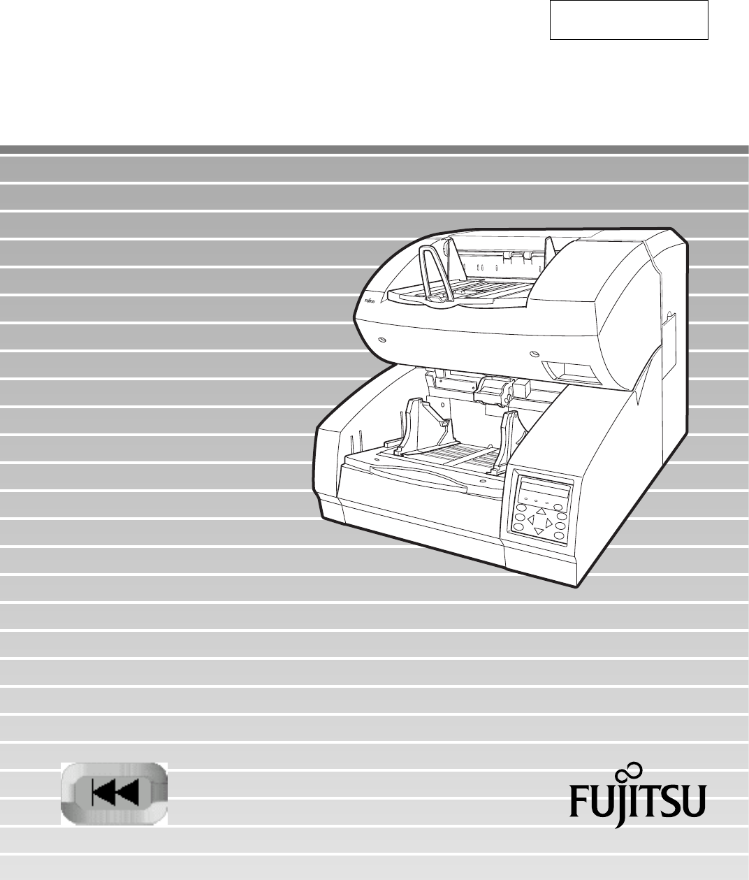
C150-E192-01EN fi-4990C Image Scanner Operator's Guide
fi-4990C Image Scanner Operator's Guide
Edition Date published 01 February, 2001 Revised contents First edition Specification No. C150-E192-01EN This equipment has been tested and found to comply with the limits for a Class A digital device, pursuant to Part 15 of the FCC Rules. These limits are designed to provide reasonable protection against harmful interference when the equipment is operated in a commercial environment.
Please send your comments on this manual or on Fujitsu products to the following addresses: North American contact: FUJITSU COMPUTER PRODUCTS OF AMERICA, INC. 2904 Orchard Parkway, San Jose. California 95134-2009, U.S.A. Phone: (1-408) 432-6333 Fax: (1-408) 894-1709 HOME PAGE: http://www.fcpa.com/ Asian contact: FUJITSU HONG KONG LTD. 10/F, Lincoln House, 979 King’s Road, Taikoo Place, Island East, Hong Kong Phone: (852) 2827-5780 Fax: (852) 2827-4724 HOME PAGE: http://www.fujitsu.com.
IMPORTANT NOTE TO USERS READ CAREFULLY ALL OF THIS MANUAL BEFORE USING THIS PRODUCT. IF NOT USED CORRECTLY, UNEXPECTED DAMAGES MAY BE CAUSED TO THE USERS OR THE BYSTANDERS.
Preface This manual explains how to use the fi-4990C image scanner. This scanner can be equipped with an optional endorser; however, Illustrations in this manual do not include the endorser except those in Chapter 5. For details of the endorser, refer to its Operator Guide. This manual contains COMPONENTS, INSTALLATION AND CONNECTIONS, OPERATING INSTRUCTION, DOCUMENT SPECIFICATION, SPECIFICATIONS, and SETUP, BROWSE, AND TEST MODES.
Conventions Special information, such as warnings, cautions, and notes are indicated as follows: WARNING WARNING indicates that serious personal injury may result if you do not follow a procedure correctly. CAUTION CAUTION indicates that minor personal injury, loss of data, or damage to the scanner may result if you do not follow a procedure correctly. NOTE NOTE indicates remarks, tips, and other useful supplementary information. The following symbols are used in this manual.
CONTENTS q CHAPTER 1 COMPONENTS Checking the Components ......................................................... 1-1 Units and Assemblies ................................................................ 1-2 Operator Panel .......................................................................... 1-5 Buzzer ....................................................................................... 1-8 q CHAPTER 2 INSTALLATION AND CONNECTIONS Precautions .......................................................
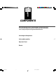
CHAPTER CHAPTER 2 INSTALLATION AND CONNECTIONS CHAPTER CHAPTER 4 3 OPERATING INSTRUCTION DOCUMENT SPECIFICATION CHAPTER CHAPTER 1 COMPONENTS 5 SPECIFICATIONS 6 SETUP, BROWSE, AND TEST MODES GLOSSARY OF TERMS INDEX COMPONENTS INSTALLATION AND CONNECTIONS OPERATING INSTRUCTION DOCUMENT SPECIFICATION SPECIFICATIONS SETUP, BROWSE, AND TEST MODES GLOSSARY OF TERMS INDEX vii 01FI.P65 7 01.2.
CHAPTER 1 COMPONENTS After unpacking the scanner, confirm that all the components have been received. This chapter describes the components of the scanner, part names, and operator panel arrangement and their function. Checking the Components Units and Assemblies Operator Panel Buzzer 02C1.P65 1 01.2.
Checking the Components These are high precision components and must be handled with care. Confirm that all the components shown in the following figure have been received. Mount the stop lever on the stacker of the scanner. If any component is missing, please contact your sales agent. Scanner * Stop lever Power cable for North America Power cable for Europe * or Operator’s Guide (this manual) and two CD-ROMs 1-1 03C1.P65 1 01.2.
Units and Assemblies This section shows the exterior view and assemblies of the scanner. This section also provides names of each part and describes their functions. Units 19 18 17 16 17 15 12 6 13 7 14 4 7 1 8 9 2 10 11 5 3 4 20 21 22 1-2 03C1.P65 2 01.2.
No. 1 2 3 4 5 6 7 8 9 10 11 12 13 14 15 16 17 18 19 20 21 22 Name Operator panel Power switch Hopper Hopper guides Hopper extension Automatic document feeder (ADF) ADF release lever Pick roller unit Guide plate Pad Brake roller Upper transport unit Lever Side cover Stacker Check stopper Stacker guides Stop lever Stacker extension Main line switch Power inlet Interface connectors Function Used to operate the scanner. Used to power on or off. Document input tray. Used to adjust the document width.
Assemblies Lower sheet guide assembly Pick roller unit Brake roller Lamp unit (back side) Pad Lamp Lamp unit (front side) Lamp Guide plate 1-4 03C1.P65 4 01.2.
Operator Panel The operator panel is located at the lower right hand side of the scanner. The panel consists of an LCD (24 character x 2 line), LEDs, and buttons. Arrangement Operator panel LCD 24 characters x 2 lines DATA CHECK POWER F1 MENU F2 ENTER F3 CANCEL 1-5 03C1.P65 5 01.2.
Button/LED Function Button name Function Turns on or off the power when the main line switch is set to “I”. MENU Sets the scanner in setup or browse mode. It is also used to set test mode. (See Chapter 6) Setup mode is used for customizing the scanner. Browse mode is used for glancing conditions of the scanner. Test mode is used for testing the scanner offline. ENTER Used in setup, browse, or test mode. CANCEL • Clears an error if any. • Used in setup, browse, or test mode.
Operation status display After power is turned on, the LCD indicates the following messages in normal mode. Please wait Wait for a moment. This is indicated when processing takes a long time. When this is displayed after turning power on, the second line indicates initializing messages. Ready The scanner can receive a command from the host computer or can be set in setup, browse, or test mode. Manual Feeding Load documents on the hopper table manually. Feeding The scanner is feeding documents.
Buzzer The scanner has a buzzer to indicate that an error has occurred or an operator panel button is pressed. The buzzer function can be set on or off by following the procedure “Buzzer” in Chapter 6 SETUP, BROWSE, AND TEST MODES. Sound condition Function Error occurred Sounds continuously. The buzzer turns off when any button is pressed or the power is turned off. Even when a button is pressed, the scanner continues to display the error. Button pressed Sounds briefly.
CHAPTER 2 INSTALLATION AND CONNECTIONS The chapter describes how to install and connect the scanner. Precautions Inspection Cable Connection 04C2.P65 1 01.2.
WARNING Place the machine with no portion of the scanner hangs over the desktop. Never attempt to move or relocate the machine without help. And hold the horizontal plane of the scanner bottom. (Not inclined plane) ACHTUNG Precautions Stellen Sie den Scanner sicher auf eine waagerechte, ebene Flache. Bewegen Sie den Scanner nicht ohne Hilfe. This section describes precautions when installing the scanner. Do not install the scanner in the following places and environments.
Inspection This section describes how to check the labels. Three labels Label C Label A Label B Label A (An example) 2-2 05C2.P65 2 01.2.
Label B (An example) MODEL fi-4990C IMAGE SCANNER PART NO. CA04315-B107 AC100-240V SER. NO. 1 phase DATE 2001-02 FUJITSU LIMITED 2.9/1.5A MADE IN 50/60Hz 65 kgf JAPAN Label C (An example) MODEL NAME fi-4990C PART NO. CA04315-B107 MODEL - 0 1 2 3 4 5 6 7 8 9 REV. - 0 1 2 3 4 5 6 7 8 9 - 0 1 2 3 4 5 6 7 8 9 2-3 05C2.P65 3 01.2.
Cable Connection This section describes how to connect the cables. Connect the cables as follows: Turning the main line switch off Press “O” side of the main line switch to turn the power off. Main line switch Connecting the power cable Connect the power cable to the power inlet of the device and a power outlet. 2-4 05C2.P65 4 01.2.
Connecting the interface cable Connect the appropriate SCSI interface cables and secure them with hooks or screws. Interface connector for SCSI Back – side Interface cable for SCSI NOTE • SCSI-ID is set to No. 5 at shipment. Refer to Chapter 6 when changing the setting. 2-5 05C2.P65 5 01.2.
Attach the stop lever to the scanner. Insert the stop lever to the scanner. (Into the gap in the stacker) 2-6 05C2.P65 6 01.2.
CHAPTER 3 OPERATING INSTRUCTION This chapter describes how to turn the power on, and also describes how to operate the operator panel (basic operation). Refer to Reference Guide about information on loading document and opening/closing the upper transport unit. Turning the Power On Basic Operation of the Operator Panel 06C3.P65 1 01.2.
3 Turning the Power On This section describes how to turn the power on. Press “I” side of the main line switch located at the back of the scanner. Press the power switch of the operator panel. The power goes on and the green POWER lamp at the operator panel lights. Main line switch Operator panel Power switch 3-1 07C3.P65 1 01.2.
Basic Operation of the Operator Panel This section describes basic operation of the operator panel including how to enter the mode selection mode in which you can use setup mode, browse mode, and test mode. Displaying detailed information if an error occurred If an error occurs, the CHECK LED blinks and the error message is displayed on the LCD. For example, the LCD indicates as follows: Hopper empty Press CANCEL to clear the error (Temporaly errors will clear, equipment errors will not). 3-2 07C3.
Lifting or lowering the hopper When the scanner has no error (the CHECK LED does not light), pressing lowers the hopper. and pressing lifts the hopper CAUTION During hopper height adjustment, do not touch the hopper table or do not put anything on the hopper table to prevent your fingers from being caught. If something is caught in the mechanism, the scanner may be damaged. This function is valid when: Ready is displayed.
Clearing a consumable life alarm This scanner has the consumable counter to estimate consumable life of the scanner. When the consumable counter reaches the prescribed value, the LCD indicates an alarm that the consumable may be expired. For example, the following message appears: Consumable life alarm AAAAAAAA MMMM In this case, press CANCEL . The LCD indicates the following message: Reset Consumable Counter? Yes:Enter No:Cancel Yes (press ENTER ): The scanner resets the consumable counter to zero.
Confirming the number of sheets processed by the scanner The LCD indicates the numbers of sheets scanned during online or in test mode (offline feed test). The LCD indicates the numbers as follows: Scanning AAAAAAAA MMMM Value Meaning Description AAAAAAAA Abrasion counter MMMM Batch counter Eight columns of numbers indicate the accumulative number of sheets fed by this scanner. Four columns of numbers indicate the number of sheets fed per hopper. 3-5 07C3.P65 5 01.2.
Using the function buttons (F1, F2, and F3) This scanner has the three function buttons ( F1 , , and ) to save time when F2 F3 using a setup function which is likely to require tedious operation. Use these buttons as shortcut keys when you frequently use certain setup functions for your jobs. See Chapter 6 for details. You can use function buttons after allocating a setup function to it. This allocation can be done in setup mode.
Using the setup, browse, and test modes This scanner has the setup mode, browse mode, and test mode to ease operation for customizing the scanner, glancing setup conditions of the scanner, and testing the scanner offline respectively. There are two ways to enter these modes: • Press MENU when the LCD indicates “Ready” or • Turn the power on while pressing MENU . Available functions differ with the two ways. For details, see Chapter 6. In the following way, you can use the setup mode and browse mode.
In the following way, you can use the test mode in addition to the setup mode and browse mode. To quit these modes, turn the power off. POWER ON with MENU ON T Please wait * : Cursor buttons : Blinking * Turn off to quit <>.
Transition of operator panel status and display The following outlines the transition of status and display of the operator panel. POWER ON POWER ON with MENU ON F1, F2, F3 Shortcut to setup functions Ready (normal mode) CANCEL Error occurred Error message MENU CANCEL Mode select screen (Setup and Browse) ENTER Turn power off to quit. CANCEL Setup mode Mode select screen (Setup, Browse, and Test) ENTER CANCEL ENTER Browse mode CANCEL Test mode 3-9 07C3.P65 9 01.2.
3-10 07C3.P65 10 01.2.
CHAPTER 4 DOCUMENT SPECIFICATION This chapter describes the document size and document quality of the scanner. Document Size Document Quality Document Limitations Grounding Color Area Drop-out Color Job separation Sheet 08C4.P65 1 01.2.
Document Size The following figure shows document sizes that the scanner can read. Feeding Direction Scanner fi-4990C B A Maximum B A 297 (11.7 in) 432 (17 in) Minimum A7 size = 74 (2.9 in) x 105 (4.1 in): Available in both portrait and landscape orientations (Unit : mm) 4-1 09C4.P65 1 01.2.
Document Quality This section describes paper types of documents and ream weights of paper available for the scanner, and precautions. Paper types of documents The recommended paper types of documents are as follows: NOTE Please use the specified paper. (In rare occasion, double feeding or document damage may occur.) • Fine paper • Plain paper • OCR paper When using any other paper types of documents, place a test batch of documents in to the ADF to see if it successfully feeds the documents.
lb indicates the pound weight of 500 sheets of 17 x 22 inch paper (3.76 g/m2). Precautions Be careful not to scan the following documents. Preliminary document feed testing may be necessary to avoid the unexpected errors. If the document slips in ADF (JAM error) or double feed occurs frequently, refer to “Improving Document Separation” in Reference Guide. • Paper with clips or staples • Paper with wet ink • Paper of which thickness is not constantly equal.
NOTE • If carbonless papers are used, clean the roller twice as often as usual. • Documents should be straightened to fit the condition below. More than 30 mm Feed direction Less than 3 mm Read surface Top of the paper More than 30 mm Feed direction Less than 5 mm Read surface • When you read curled, wrinkled, or creased documents, documents may not be successfully arranged in the stacker. 4-4 09C4.P65 4 01.2.
Document Limitations This section describes restrictions on document used for the scanner. Areas that must not be perforated Perforatins are prohibited in the shaded area of Figure 4.1 to avoid document size detection error or job separation sheet detection error or jam. 113 (4.45") 79 (3.12") Document feeding direction (Unit : mm) 96 (3.78") 10 10 12 12 10 10 (0.39") (0.39") (0.47") (0.47") (0.39") (0.39") 15 (0.59") Reading reference position 134 (5.
Print phohibit areas on the front and back surfaces Printing in area A on the front of a document may, in a rare case, cause a document size detection error. Printing in area B on the front and back of document may, in a rare case, result in a double feed error. Figure 4.2 shows print prohibit areas on the front and back surfaces. NOTE Figure 4.2 shows the document as viewed from the reading surface. 113 (4.45") 79 (3.12") 134 (5.28") (Unit : mm) 96 (3.
Grounding Color Area As Figure 4.3 shows, the top 3-mm part of the read area on each surface should be left blank (grounding color) by specifying a drop-out color. If the drop-out color cannot be specified, select “Photo” for the document type (linedrawing or photograph). For details of the drop-out color, see Page 4-8. Main scanning direction Reading reference Grounding color (white) or drop-out color area Subscanning direction 3 mm (0.12") Figure 4.3 Grounding color area 4-7 09C4.P65 7 01.2.
Drop-out Color A drop-out color is a color visible by a human eye but not visible to the scanner. To check the grounding color of document for a drop-out color, use the method and follow the standards given below. Print density measurement The spectrum chart shown in Figure 4.4 is used to measure print density. The measurement must be made in one of the following ways: • A light source using fluorescent. • Macbeth PCS meter PCM II is used, which requires a filter.
Job Separation Sheet Shape The following Figure 4.5 shows the shape of the document. (0.59") Scanning direction 15 15 (0.59") Center of document (Unit : mm) more than 210 (8.27") Figure 4.5 Shape of document Document type The document type and ream weight specifications given in Section 4-2 apply. However, the document size shall be A4 or larger (210 mm (8.27”) or more wider). 4-9 09C4.P65 9 01.2.
CHAPTER 5 SPECIFICATIONS This chapter describes the installation specifications, external dimensions, consumables, option. Installation Specifications External Dimensions Consumables Options 10C5.P65 1 01.2.
Installation Specifications The following table lists the installation specifications of the scanner. Item Dimensions (mm) Weight (kg) Input power Width 590 (23.2 in) Depth 690 (27.2 in) Height 540 (21.3 in) without optional endorser 610 (24.0 in) with optional endorser 65 (143 lb.
External Dimensions (unit: mm) 5-2 11C5.P65 2 01.2.
Consumables The following table lists consumables used for the scanner. Be sure to keep some consumables in stock. Customer is responsible to change these items periodically. The consumable counter can be used to check the number of scanned documents. (See page 3-4, 6-22.) Name Specification Service life and remarks Lamp CA04315-0430 1000 hours or more. Two lamps used per scanner. Pad CA04315-G730 300,000 sheets or one year. Pick roller unit CA04315-F711 300,000 sheets or one year.
Options The following table lists options of this scanner. Name Specification Remark Endorser CA04315-D201 Ink jet printing method • Back-side print • Max. 33 characters Contact your Fujitsu sales agent for more information. 5-4 11C5.P65 4 01.2.
CHAPTER 6 SETUP, BROWSE, AND TEST MODES This chapter describes the setup, browse, and test modes of the scanner. Setup, Browse, and Test Modes Activating the Setup or Browse Mode Contents of the Setup or Browse Mode Activating the Test Mode Contents of the Test Mode 12C6.P65 1 01.2.
Setup, Browse, and Test Modes This scanner has the setup mode, browse mode, and test mode to ease setting up. • Setup mode for customizing the scanner for user requirements • Browse mode for glancing setup conditions of the scanner • Test mode for testing the scanner offline There are two ways to enter these modes: • Way 1 Press MENU when the LCD indicates “Ready”. You can use the setup mode and browse mode. To quit a mode, press CANCEL . • Way 2 Turn the power on while pressing MENU .
Activating the Setup or Browse Mode To activate the setup mode, follow these steps: 1. While the LCD is indicating “Ready”, press MENU . The <> screen appears with “SETUP” blinking. Ready <> SETUP BROWSE 2. 3. Press ENTER . The <> initial screen (*) appears. * <> Initial screen Press ENTER . The <> menu screen (**) appears.
Mode selection ( MENU pressed in Ready status) There is another mode selection which enables you to execute the user test on the scanner without the host computer. See “ Activating the Test Mode” later in this chapter.
Contents of the Setup or Browse Mode This section describes the contents of the setup mode. The setup mode can be classified into 35 types. Setup item Description Remarks Paper length check The selection set by the host computer cannot be changed. The selection set by the host computer cannot be changed. Drop-out color Enables or disables the function which detects a paper length error. Enables or disables the function which detects the paper thickness.
Setup item Description Remarks TP_IF baud rate SCSI ID Selects the control data transfer rate (2400, 4800, 9600, or 19200) for the TP interface. Sets the SCSI ID of this scanner. Product ID Sets the product ID of this scanner. Displayed in setup mode selected by turning power on with MENU pressed. Displayed in setup mode selected by turning power on with MENU pressed. Displayed in setup mode selected by turning power on with MENU pressed. Pre-pick Pick start time Enables or disables pre-picking.
Transition of screens in setup mode This flowchart indicates the transition of screens in setup mode for reference to the setup operation described in the following pages.
Paper length check This function sets and detects a difference in paper length. You cannot change settings if they are set by the host computer. LCD display Options Paper Length Check On, Off (Default: Off) 10 mm, 15 mm, 20 mm (Default: 10 mm) Remarks Checked or not Difference: XX mm means that it is not regarded as an error when the actual difference of paper length is within the limits of ±XX mm. The following is an example of operation when you use this function. 1.
6. When the desired value appears, press ENTER to save the change. The LCD returns to the <> menu screen (Paper Length Check). 7. Press CANCEL two times. The LCD returns to the Ready screen. <> Paper Length Check Ready Doublefeed check This function determines whether or not to enable the paper thickness which is set by the “paper thickness setup” function to detect a double feed error. You cannot change settings if they are set by the host computer.
3. Press ENTER . The option select screen appears with the current option MODE blinking (blinking indicates “changeable”). 4. Press ENTER . The option select screen appears with the current option OFF blinking (blinking indicates “changeable”). Doublefeed Check : MODE OFF 5. Press or . The displayed option changes (Thickness Check or Thickness & Roller). Doublefeed Check : MODE Thickness & Roller 6. Press ENTER to save the change.
11. Press CANCEL two times. The LCD returns to the Ready screen. Ready Paper thickness setup This function sets the paper thickness which is used as the reference for detecting a double feed error. Whether this function is enabled or disabled is determined by the “paper thickness check” function in setup mode. NOTE This setting cannot be displayed in browse mode. The following is an example of operation when you use this function. 1. In <> initial screen, press ENTER .
5. 6. Press ENTER . The “Adjusting!!” message appears. The scanner lifts the hopper, feeds the paper, adjusts the sensing level of the sensor, and saves its value. After adjustment, the sheet is ejected and the “Finished!!” message appears for two seconds, then the LCD returns to the <> menu screen (Paper Thickness Setup). If an error (for example, Mis-pick) occurs during adjustment, remove the paper and press CANCEL . The paper load prompting screen appears again. Repeat steps 4 and 5.
Skew check This function determines if abnormal skew is detected or not. You cannot change the setting if it is set by the host computer. LCD display Options Skew Check On, Off (Default: Off) Remarks The following is an example of operation when you use this function. 1. In <> initial screen, press ENTER . The <> menu screen (Paper Length Check) appears. <> <> Paper Length Check 2. Press three times.
IPC-3 mode This function selects a pattern to be set in the IPC-3 image processing feature. LCD display Options IPC-3 Mode 0, 1, 2, 3, 4, 5 (Default : 0) Remarks 0: do not select any pattern 1 to 5: select pattern numbers 1 to 5 The following is an example of operation when you use this function. 1. In <> initial screen, press ENTER . The <> menu screen (Paper Length Check) appears. <> <> Paper Length Check 2. four times.
NOTE When you set from the Function Key, the dialogue appears whether you want to save the revised data. If you want to save the process, press “ENTER”key. And if you do not want to save the process, press “CANCEL”key. 6. Press CANCEL two times. The LCD retarns to the Ready screen. Ready Paper types and corresponding pattern numbers User’s paper is classified into five types in line art (no halftone) mode as shown in the following table.
Important When scaned in Grayscale or color, this setting is not in Effect. only effective when scaned in Binary. Reading parameter validity Reading parameter Reading mode Valid Resolution X Line-art/ Photo Halftone DTC Paper Size X X Invalid X Portrait/ Landscape Picking X X X Sharpness Outline extraction Simplified DTC X X X X Reading parameter Document selection Valid r patterns Contrast Automatic separation X Conversion X X Invalid X X 6-15 13C6.P65 15 01.2.
Hopper height This function sets the initial height of the hopper. Set the height which you frequently use. LCD display Options Hopper Height 250 sheets, 500 sheets, 1000 sheets (Default : 1000 sheets) Remarks The following is an example of operation when you use this function. 1. In <> initial screen, press ENTER . The <> menu screen (Paper Length Check) appears. <> <> Paper Length Check 2.
If an error occurs during positioning, press CANCEL . The LCD returns to the option select screen. Repeat step 4. 5. Press CANCEL three times. The LCD returns to the Ready screen. Ready After this setting, the hopper is set at the new height whenever power is turned on. Paper separation level This function sets the power of the brake roller for stabilizing paper separation in picking documents.
Set “braking power” according to the table below. Setting Thick Braking power Very strong Medium Thick Strong Normal Medium (factory default) Medium Thin Light Thin “Double feed” frequently occurs. “Mis-pick” or “SF2 ···” frequently occurs. Make the braking power stronger. Make the braking power weaker. Very light The following is an example of operation when you use this function. 1. In <> initial screen, press ENTER . The <> menu screen (Paper Length Check) appears.
5. When the desired option appears, press ENTER to save the change. The LCD returns to the <> menu screen (Paper Separation Level). 6. Press CANCEL two times. The LCD returns to the Ready screen. <> Paper Separation Level Ready 6-19 13C6.P65 19 01.2.
Drop-out color This function sets a drop-out color for front and back sides of paper respectively. You cannot change settings if they are selected by the host computer. LCD display Options Drop-out Color Front: Green, Red, Blue (Default: Green) Back: Green, Red, Blue (Default: Green) Remarks The following is an example of operation when you use this function. 1. In <> initial screen, press ENTER . The <> menu screen (Paper Length Check) appears.
6. When the desired option appears, press ENTER to save the change. The LCD returns to the <> menu screen (Drop-out Color). 7. Press CANCEL two times. The LCD returns to the Ready screen. <> Drop-out Color Ready Background changeover This function sets the Background to “White” or “Black”.
4. Press . White (current option for Back) blinks (blinking indicates “changeable”). Background Changeover F: White B: White 5. Press or . The displayed option changes (Black). Background Changeover F: White B: Black 6. Press ENTER to save the change. The LCD returns to the <> menu screen (Background Changeover). <> Background Changeover 7. Press CANCEL two times. The LCD returns to the Ready screen.
1. In <> initial screen, press ENTER . The <> menu screen (Paper Length Check) appears. <> <> Paper Length Check 2. Press repeatedly until “Consumable Counter” appears in the lower line of the menu screen. <> Consumable Counter 3. Press ENTER . The option select screen appears with the current value blinking (blinking indicates “changeable”). Consumable Counter 256 0000 sheets 4. Press or . The displayed value changes (1 to 256).
Consumable counter reset This function is to be used when the consumable parts are replaced before the accumulated value of the consumable conter reaches to the setting value. NOTE You cannot use this function when the setup mode is brought by pressing “MENU” in the Ready status. LCD display Options Remarks Consumable Counter Reset YES, NO (Default) YES: Reset the accumulated consumable counter value. NO: cancel the resetting of consumable counter value.
5. When the desired option appears, press ENTER to resetting the Consumable Counter. The LCD returns to the <> menu screen (Consumable Counter Reset). Finished resetting!! 6. To quit the <>, turn off the power. <> Consumable Counter Reset Consumable alarm mode This function is to be used how to notify the alarm generation when the accumulated consumable counter value reaches to the setting value.
The following is an example of operation when you change the setting. 1. <> initial screen, press ENTER . The <> menu screen (Paper Length Check) appears. <> <> Paper Length Check 2. repeatedly until “Consumable Press Alarm Mode” appears in the lower line of the menu screen. <> Consumable Alarm Mode 3. Press ENTER . The current option list screen appears with “Alarm & Stop scanning” blinking (blinking indicates “changeable”).
Buzzer This function enables or disables the buzzer sound when an error occurs. NOTE The buzzer sounds regardless of this setting when use this function. LCD display Options Buzzer On, Off (Default: Off) Remarks The following is an example of operation when you use this function. 1. In <> initial screen, press ENTER . The <> menu screen (Paper Length Check) appears. <> <> Paper Length Check 2.
Buzzer volume This function sets the sound volume of the buzzer in seven steps. NOTE This setting is valid both for occurrence of an error and for press of an operator panel button. LCD display Options Buzzer Volume qqqqqq to nnnnnn Remarks (Default: n n q q q q) Minimum to (seven steps) Maximum * Symbols of volume may differ from the actual symbols used in the LCD. The following is an example of operation when you use this function. 1. In <> initial screen, press ENTER .
5. When the desired option appears, press ENTER to save the change. The LCD returns to the <> menu screen (Buzzer Volume). 6. Press CANCEL two times. The LCD returns to the Ready screen. <> Buzzer Volume Ready LCD contrast This function sets the contrast of the LCD on the operator panel in seven steps.
4. Press or . The displayed option changes (n n n q q q to n n n n n n, q q q q q q or n q q q q q). LCD Contrast Dark n n n q q q Bright 5. When the desired option appears, press ENTER to save the change. The LCD returns to the <> menu screen (LCD Contrast). <> LCD Contrast 6. Press CANCEL two times. The LCD returns to the Ready screen. Ready Picking speed This function sets the rotational speed of the pick roller.
The following is an example of operation when you use this function. 1. In <> initial screen, press ENTER . The <> menu screen (Paper Length Check) appears. 2. repeatedly until “Picking Speed” Press appears in the lower line of the menu screen. 3. Press ENTER . The option select screen appears with the current setting Fast blinking (blinking indicates “changeable”). 4. or . Press The displayed option changes (Fast to Slow). 5. Press ENTER to save the change.
The following is an example of operation when you use this function. 1. In <> initial screen, press ENTER . The <> menu screen (Paper Length Check) appears. <> <> Paper Length Check 2. Press repeatedly until “TP_IF Baud Rate” appears in the lower line of the menu screen. <> TP_IF Baud Rate 3. Press ENTER . The option select screen appears with the current setting 9600 blinking (blinking indicates “changeable”). TP_IF Baud Rate 9600 4.
SCSI ID This function sets the ID number for the SCSI interface. NOTE You cannot use this function when the setup mode is brought by pressing status. LCD display Options SCSI ID 0 to 7 (Default: 5) MENU in the Ready Remarks The following is an example of operation when you use this function. 1. In <> initial screen, press ENTER . The <> menu screen (Paper Length Check) appears. <> <> Paper Length Check 2.
Product ID This function sets the product ID of the scanner. Usually, you need not change this setting. NOTE You cannot use this function when the setup mode is brought by pressing status. MENU LCD display Options Remarks Product ID Fi-4990C, M4099DC, M3099G (Default: Fi4990C) Model number of this scanner in the Ready * The model number of this scanner is Fi-4990C. The following is an example of operation when you use this function. 1. In <> initial screen, press ENTER .
6. To quit the <>, turn off the power. Pre-pick This function enables or disables paper pre-picking. LCD display Options Pre-pick On, Off (Default: On) Remarks The following is an example of operation when you use this function. 1. In <> initial screen, press ENTER . The <> menu screen (Paper Length Check) appears. <> <> Paper Length Check 2. Press repeatedly until “Pre-pick” appears in the lower line of the menu screen. 3.
Pick start time This function sets the period from when paper is manually put on the hopper to when the pick operation starts. LCD display Options Remarks Pick start time 00.2 S to 29.8 S (Default: 01.0 S) In units of 0.2 second The following is an example of operation when you use this function. 1. In <> initial screen, press ENTER . The <> menu screen (Paper Length Check) appears. <> <> Paper Length Check 2.
Manual feed timeout This function sets the waiting time from when the host computer issues a scan command to when paper is manually put on the hopper. A manual feed timeout error occurs if this time elapses without putting paper on the hopper. LCD display Options Remarks Manual Feed Timeout 1 S to 255 S (Default: 30 S) Unit: second The following is an example of operation when you use this function. 1. In <> initial screen, press ENTER .
6. Press CANCEL two times. The LCD returns to the Ready screen. Ready Paper pick retry This function sets the pick motor rotation period and the retry count. LCD display Options Remarks Paper Pick retry Step: 1 to 7 (Default: 2) 1 to 7: one time to seven times the standard steps 1 to 7: one retry to seven retries Times: 1 to 7 (Default: 4) The following is an example of operation when you use this function. 1. In <> initial screen, press ENTER .
5. Press or . The displayed option changes (1, 2, 3, 4, 5, 6, 7). Paper Pick retry Step: 2 Times: 7 6. When the desired value appears, press ENTER to save the change. The LCD returns to the <> menu screen (Paper Pick retry). <> Paper Pick retry 7. Press CANCEL two times. The LCD returns to the Ready screen. Ready Paper feed retry This function sets the feed motor rotation period and the retry count.
3. Press ENTER . The option select screen appears with the current setting 1 (for Step) blinking (blinking indicates “changeable”). Paper Feed retry Step: 1 Times: 4 4. Press . The current count setting 4 blinks. Paper Feed retry Step: 1 Times: 4 5. or . Press The displayed option changes (1, 2, 3, 4, 5, 6, 7). Paper Feed retry Step: 1 Times: 7 6. When the desired value appears, press ENTER to save the change. The LCD returns to the <> menu screen (Paper Feed retry). 7.
Allocatable setup functions and other special functions Setup functions noted above START key EJECT key (Default: Undefined) Remarks START: starts the operation stopped by EJECT and sends data to the host computer. EJECT: stops operation and ejects the paper in the transport unit. The , ,or button can be used as a shortcut key which enables you to access F1 F2 F3 the allocated setup function just by pressing the button whenever the scanner is in the Ready state.
6. 7. When START key is displayed, press ENTER . The LCD returns to the function key select screen with F1 blinking. Press F2 blinks. F1 Function Key F2 F3 F1 Function Key F2 F3 once. 8. Press ENTER . The F2 selection screen appears with the current setting Undefined blinking (blinking indicates “changeable”). F2 selection Undefined 9. or . Press The setup functions, START key, and EJECT key are displayed in sequence at the lower line. F2 selection EJECT key 10.
To cancel the setup mode lock state, turn off the power and turn on the power while pressing the MENU button to enter the setup mode. In the setup mode, select the Setup Mode Lock function and set the option to OFF. The following is an example of operation when you use this function. 1. In <> initial screen, press ENTER . The <> menu screen (Paper Length Check) appears. <> <> Paper Length Check 2.
Language This function is to set the LCD display English or Japanese. LCD display Options Language English, Remarks (Default: English) The following is an example of operation when you change the setting. 1. <> initial screen, press ENTER . The <> menu screen (Paper Length Check) appears. <> <> Paper Length Check 2. Press repeatedly until “Language” appears in the lower line of the menu screen. <> Language 3. Press ENTER .
White follower mode Sets the mode how to follow the white color as the reference when scanning papers. When the whole background of a paper is colored and “1” is set in this mode, scanner scan the leading edge of the paper as the white reference. Then the background of the scanned image will be white. NOTE 1. About 3mm from the leading edge of a document must be the same color when setting “1”. 2. You cannot use this function when the setup mode is brought by pressing “MENU” in the Ready status.
5. When the desired option appears, press ENTER to save the change. The LCD returns to the <> menu screen (White follower mode). 6. To quit the <>, turn off the power. <> White follower mode Interface board slot This function activates one interface board while 2 interface boards are mounting. NOTE You cannot use this function when the setup mode is brought by pressing status.
3. Press ENTER . The option select screen appears with the current setting AUTO blinking (blinking indicates “changeable”). Interface Board Slot AUTO 4. Press or . The displayed option changes (SLOT 1 or SLOT 2 blinks). Interface Board Slot SLOT 1 5. When the desired option appears, press ENTER to save the change. The LCD returns to the <> menu screen (Interface Board Slot). <> Interface board Slot 6. To quit the <>, turn off the power.
LCD display Options SCSI Bus Width Setting 16 bit, 8 bit (Default: 16 bit) Remarks The following is an example of operation when you use this function. 1. In <> initial screen, press ENTER . The <> menu screen (Paper Length Check) appears. <> <> Paper Length Check 2. repeatedly until “SCSI Bus Width Press Setting” appears in the lower line of the menu screen. <> SCSI Bus Width Setting 3. Press ENTER .
Activating the Test Mode To activate the test mode: 1. Turning power on with MENU pressed. The LCD indicates “Please wait” then “<>” with “SETUP” blinking. T Please wait <> SETUP BROWSE TEST 2. 3. 4. Press twice. “TEST” blinks (blinking indicates “selectable). <> SETUP BROWSE TEST Press ENTER . The <> initial screen (*) appears. * <> Initial screen Press ENTER . The <> menu screen (**) appears.
Mode selection (power on with MENU pressed) POWER ON with MENU ON T Please wait * : Cursor buttons : Blinking * Turn off to quit <>.
Contents of the Test Mode The test mode includes the user test functions listed in the following table. This section explains “Offline feed test”, “Options”, and “Device life” which are necessary for users. NOTE If you need to use test functions other than “Offline feed test”, “Options”, and “Device life”, contact your dealer. The user test functions are as follows: Test item Description Offline feed test Scans sheets continuously for checking conditions of paper feeding.
Offline feed test This function scans sheets of paper continuously for checking entire operation of the mechanism without a host computer. You can use the Settings function in setup mode to modify scanning parameters (scanning mode, paper size/orientation, density, resolution, and halftone processing) for scanning documents. LCD display Test items Remarks Offline Feed Test START and SETUP START: begins the test. SETUP: changes settings of scanning parameters.
7. Press ENTER . The PAPER SIZE screen appears with the current setting A4P blinking (blinking indicates “changeable”). PAPER SIZE A4P 8. Press or . The displayed parameter changes (LTP, B5P, A5P, A4L, etc.). PAPER SIZE LTP 9. When the desired parameter appears, press ENTER to save the change. The parameter set screen appears with the new parameter blinking. 10.
Options This function displays the options installed in the scanner. LCD display Displayed options Remarks Options Endorser Endorser: printer that prints back side of documents. * When an option is installed, ON is displayed under the option. When an option is not installed, OFF is displayed under the option. The following is an example when you use this function. 1. 2. 3. 4. In the <> initial screen, press ENTER . The <> menu screen (Offline Feed Test) appears. Press .
Device life This function displays the cumulative number of sheets fed and the cumulative number of hours during which the lamp is lit since the scanner has been installed. These values are helpful for estimating the life of devices. LCD display Displayed devices Remarks Device Life COUNT, LAMP F, and LAMP B COUNT: accumulative number of sheets fed. LAMP F: accumulative number of operating hours for the front-side lamp. LAMP B. accumulative number of operating hours for the back-side lamp.
6-56 15C6.P65 56 01.2.
GLOSSARY OF TERMS A4 size A standard paper size used in Japan and other countries. Paper size is 210 x 297 mm (8.25 x 11.6 inches). ASCII The acronym for American Standard Code for Information Interchange. ASCII is a set of 128 codes (numbered 0 to 127) used to communicate information between a computer and another device such as scanner. Automatic separation The image processing method to detect the difference between text and photos and choose the threshold accordingly.
Dither Technique for producing halftone images representing grayscale by using a pattern of the two pixel levels black and white. dpi Dots per inch. Drop-out color A color which is used to illuminate the document but does not appear in the read image. Duplex reading mode Both sides of the document are read in this mode. Endorser The unit for printing characters before or after scanning. These character may be used for collation of the documents and the image data.
Front-side reading = Front-side scanning Refers to reading the front-side of the document, specifically in Duplex reading mode. Halftone processing Used to reproduce photographs which usually contain different shades to display images. These shades are composed of dots resulting in a binary image. Dithering and error diffusion processing are examples of the halftone processing. Hexadecimal A base-16 numbering system (also commonly referred to as hex numbers).
IRAS Initialization of the hardware. Landscape A document is transported and read with the long side horizontal to the moving direction. Letter size A standard paper size used in the U.S.A. and other countries. Paper size is 8-1/2 x 11 inches (215.9 x 279.4 mm). Linedrawing mode Selecting linedrawing mode makes threshold and contrast settings effective but prevents brightness from being set. The specified threshold value determines whether black or white pixels are scanned.
Paper Jam A warning informing the user that document is jammed in the transport unit, or that transportation is disabled because the transport unit is slippery. This warning also appears when a double fed is detected. Photograph mode (White level follower OFF) Selecting photograph mode makes brightness and contrast settings effective but prevents the threshold from being set.
SCSI-ID Used to specify a particular SCSI device when the initiator selects a target or the target re-connects to the initiator. Serial interface A standard computer interface. Information is transferred between devices over a single wire (although other wires are used for control). With a serial interface, an interface cable greater than 3 meters (10 feet) can be used. This is often necessary in networking environments, where the scanner may be shared.
INDEX A Abrasion counter 3-5 Activating the Setup or Browse Mode 6-2 Test Mode 6-49 ADF release lever 1-3 Ambient condition 5-1 Arrangement 1-5 Assemblies 1-4 Automatic document feeder (ADF) 1-3 B Background chageover 6-21 Basic Operation of the Operator Panel 3-2 Batch counter 3-5 Brake roller 1-3, 1-4, 5-3 Braking power 6-18 Browse mode 3-7 Button /LED Function 1-6 Button functions in setup or browse mode 6-2 in test mode 6-49 Buzzer 1-8, 6-27 Buzzer volume 6-28 C Cable Connection 2-4 CANCEL button 1
Functions not available in browse mode 6-1 in setup mode 6-1 G Guide plate 1-3, 1-4 H Hopper 1-3 Hopper extension 1-3 Hopper guide 1-3 Hopper height 6-16 Hopper height adjustment 3-3 I L IMPORTANT NOTE TO USERS Input power 5-1 Inspection 2-2 Installation Specifications 5-1 Interface cable 2-5 connectors 1-3 Interface board slot 6-46 IPC-3 mode 6-13 Label A 2-2 B 2-3 C 2-3 Language 6-44 Lamp 1-4, 5-3 Lamp unit 1-4 LCD 1-5, 1-6 LCD contrast 6-29 LCD Display 1-6 LED 1-6 Lever 1-3 Lifting or lowering the
SCSI Bus width setting 6-47 SCSI-ID 6-33 Setup mode lock 6-42 Skew check 6-12 TP_IF baud rate 6-31 White follower mode 6-45 Setup mode 3-7, 6-1 Setup mode, contents of 6-4 Setup mode lock 6-42 SF2 did not detect leading edge of paper 6-17 Side cover 1-3 Skew check 6-12 Specifications 5-1 Stacker 1-3 Stacker extension 1-3 Stacker guide 1-3 START key 6-41 Satus display, transition of 3-9 Stop lever 1-1, 1-3 Pre-pick 6-35 Product ID 6-34 R Reading parameter 6-15 Ream weightr of paper 4-2 S Scanner 1-1 SCS
Upper transport unit 1-3 Using the function buttons 3-6 Using the setup, browse, and test modes 3-7 IN-4 V VDC-C revision 6-51 W Weight 5-1 White follower mode 6-45 White balance adjustment 6-51
18CE.P65 1 01.2.
fi-4990C Image Scanner Operator's Guide This manual uses recycled paper.