AN706-00044-1v0-E 32-BIT MICROCONTROLLER MB9B100A/MB9B300A/MB9B400A/MB9B500A Series FM3 family inverter solution GUI User Manual TM ARM and Cortex-M3 are the trademarks of ARM Limited in the EU and other countries.
AN706-00044-1v0-E All Rights Reserved. The contents of this document are subject to change without notice. Customers are advised to consult with FUJITSU sales representatives before ordering.
AN706-00044-1v0-E Revision History Rev Date Remark 1.0 Jul.
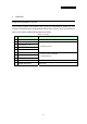
AN706-00044-1v0-E Table of Contents Revision History.................................................................................................................... 2 Table of Contents.................................................................................................................. 3 1 Introduction.................................................................................................................... 4 2 System requirements.................................................
AN706-00044-1v0-E 1 Introduction This user manual describes how to use FUJITSU’S FM3 Inverter Platform GUI. In Chapter 2, it explains system requirements for the GUI software. In Chapter 3, it explains how to install the GUI software. In Chapter 4, it explains how to install the communication driver (FTDI). In Chapter 5, it explains how to use the GUI.
AN706-00044-1v0-E 2 System requirements The GUI software supported environment on PC 2.1 Supported Operating Systems: Windows Server 2003, Windows Server 2008, Windows Vista, Windows XP, Windows 7 1. Microsoft Windows XP Service Pack 2 or Service Pack 3 Minimum of 192 MB of RAM (384 MB preferred) At least a 1 GHz processor (1.6 GHz preferred) 2. Microsoft Windows Vista or Windows Vista SP1 Minimum of 768 MB of RAM (1 GB preferred) At least a 1.6 GHz processor (2.2 GHz preferred) 3.
AN706-00044-1v0-E 3 Install GUI Install the GUI software in your PC This FUJITSU’S FM3 Inverter Platform GUI is given by compressed file, please copy and unzip the “FUJITSU’S FM3 Inverter platform GUI.zip” file to your PC. Then, you will find 10 files in the “FUJITSU’S FM3 Inverter platform GUI” folder. Table 3-1: GUI files File name 1 ARMInverterPlatform.exe 2 Electromotor_Ch.xsd 3 Electromotor_En.xsd 4 System_Ch.xsd 5 System_En.xsd 6 employeeCompressor.xml 7 employeeFan.
AN706-00044-1v0-E 4 Simply install steps about the communication Driver A simply install steps for the FTDI. 4.1 To install FTDI driver in Windows XP Simply install steps: 1. Connect the FTDI device (board) to a USB port on the PC. 2. New Hardware Wizard will launch. 3. Select "Install from a list or specific location (Advanced)". 4. Select "Search for the best driver in these locations" and enter the file path in the combo-box. 5. Install the “ftd2xxx.dll”file in the PC. 6.
AN706-00044-1v0-E 5 How to use the GUI Introduce the GUI software 5.1 Overview This GUI use to cooperate with the FUJITSU’S FM3 inverter platform, customer can use this GUI to: 1. Real-time control the motor and PFC module function; 2. Real-time setting the motor functions and parameters; 3. Real-time observation of motor running state, used variables and current waveform shape. 4. Real-time observation of system information, and so on.
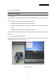
AN706-00044-1v0-E 5.3 GUI Startup Open the folder; double click the “ARMInverterPlatform.exe” to run the software, as Figure 5.2.
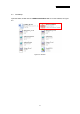
AN706-00044-1v0-E 5.4 GUI software windows’ name and function 5.4.1 Inverter Platform software introduce. - Name: Platform - Function: language setting, contain all function windows, and so on.
AN706-00044-1v0-E 5.4.2 Main window - Name : - Function: Main window connect control, start/stop control, function/parameter setting, Constant/variable observation, language setting, and current state.
AN706-00044-1v0-E 6 Constant observation Observe system state, motor state, motor parameter, and so on. If the button is pushed, the constant window opens. (See Chapter 4.4.6) 7 Variable observation Observe measure value with variable. If the button is pushed, the variable window opens. (See Chapter4.4.5) 8 Graphic Observe measure value with wave. If the button is pushed, Figure4-3 of the graphic window opens. (See Chapter 4.4.
AN706-00044-1v0-E 5.4.3 Function/parameter settings window - Name : function/parameter settings window - Function: motor selection, motor function setting and comeback default, motor parameter setting and comeback default, save config file, load config file.
AN706-00044-1v0-E Table 5-2: setting window function Name of area Specification 1 Motor selection Select which motor need to set, compressor / fan 2 Motor function set Function set 3 Motor parameter set Parameter set 4 Parameter type selection Selection motor parameter type 5 Config file save and load Save and load config file 6 Set and default button Set/default the parameter and function to hardware - Notice: - The hardware cannot be mounted Fan motor. So the function is ignored.
AN706-00044-1v0-E - How to operation of “Function/parameter settings window” Open this window and you can see the default parameters values. If you want to change the value, after connecting to the board, (1) Select the parameter (2) Change the value directly (and the changed value becomes red) (3) Push “set” button on the right. (4) Be sent the value to MCU and set it.
AN706-00044-1v0-E If you want to save the setting value, after connecting to the board and setting some parameters, (1) Push “saveconfig” button under the window. (2) Select the saving folder and name the .aip file (3) Push save button and the configuration file is saved. If you want to load the configuration file, after connecting to the board, (1) Push “loadconfig” button under the window. (2) Select the loaded .aip file (3) Push open button and the configuration file is loaded.
AN706-00044-1v0-E 5.4.
AN706-00044-1v0-E Table 5-3: select signal function Name of area Specification 1 Signal page selection Select the signal page 2 Available signals Select the signal (most 4 signals in wave, most 10signals in variable ) 3 Selected signal type Select the signal type 4 selected signals Show the selected signals 5 Operation button Set / cancel. If the button is selected, Figure4.4-5 of the graphic window opens. (See Chapter 4.4.4) - Notice: - This window can select compressor contents.
AN706-00044-1v0-E 5.4.5 Graphic window - Name : wave observer window - Function: window name set, real-time drawing the wave, showing the selection signal name, setting the wave station, run/pause set, save/load wave data, current state.
AN706-00044-1v0-E Table 5-4: wave observer function Name of area Description 1 Form name Custom the name of this wave window. 2 Show wave Draw the wave of signal needing to show. 3 Waveform name 4 Select signal 5 Wave setting 6 Other function Pause/run and save/load wave data.
AN706-00044-1v0-E Reference line of Wave A Reference line of Wave B Reference line of Wave C Reference line of Wave D You can change the waveform color each other. Select the waveform you want to change at the select wave menu. Then, choose Wave Color button and select the color you want to change.
AN706-00044-1v0-E Also, you can adjust the waveform position each other. Select the waveform you want to adjust at the selectwave menu, and push the up / down arrow button, so the waveform can be adjusted. You can adjust the X and Y grid unit each other. Set the value in the X and Y gird box directly, you can set them. When you select one waveform, you can see the unit under the window. But when you select over two waveforms, you cannot see it.
AN706-00044-1v0-E 5.4.6 Variable window - Name: variable observation window. - Function: show the signal value, select signal. 1 2 Figure 5-8: variable observation window Table 5-5: variable observation function Name of area Specification 1 Variable value Show the value form hardware 2 Select signal button Into select the signal window - Notice: - This window can select compressor contents. System and Fun contents cannot be selected.
AN706-00044-1v0-E 5.4.7 Constant window - Name : - Function: Constant observation window show the signal value; select signal. 1 2 Figure 5-9: Constant observation window Table 5-6: Constant observation function Name of area Specification 1 Select page Select need to show page 2 Parameter constant Show the constant about parameter - Notice: - This window can be shown compressor contents. Fun contents cannot be shown.
AN706-00044-1v0-E 5.5 Example of total operating Procedure This chapter introduces the operating method of GUI. 5.5.1 Hardware preparation Before operating GUI, prepare hardware according to the following procedure. 1. Install the FTDI driver (Only once) 2. Prepare the hardware environment 3. Connect the wires among the hardware board, FTDI device, PC and so on. 4. Turn on the Hardware power. 5.5.2 GUI software operating step The following part is an example of GUI operating method.
AN706-00044-1v0-E 1 Figure 5-10: operation: connect 26
AN706-00044-1v0-E (2) Start running the motor Next, click Compressor Start-stop Control button in Main Window to start the motor (1 in the Figure 5-11). If succeeds, the color of Compressor Start-stop Control button changes from green to red. The button text changes from Run to Stop.
AN706-00044-1v0-E (3) Set the motor function/parameter To set the function/parameter of motor, click Function/Parameter Setting button in Main Window (1 in Figure 5-12), and the Configuration Window in Figure4.5-4 is displayed. 1 Figure 5-12: operation: open configuration window The following example shows the operation of changing motor speed. Select Compressor tab in Function/parameter Settings window (1 in Figure 5-13).
AN706-00044-1v0-E 1 3 2 Figure 5-13: operation: set compressor parameter 29 4
AN706-00044-1v0-E (4) Show the wave To display the waveform, click Graphic button in Main Window (1 in Figure 5-14), and the Graphic Window in Figure 5-15 is displayed.
AN706-00044-1v0-E 1 Figure 5-15: operation: open the select signal window Click Select Signal button (1 in Figure 5-15) to select the signal for waveform display, and the Signal Selection Window in Figure 5-16is displayed. The following example shows the waveform display of U, V, and W phase current. Select Compressor tab in Signal Selection Window (1 in Figure 5-16). Select Current signal or All signals in Signal type (2 in Figure 5-16).
AN706-00044-1v0-E 1 3 2 4 Figure 5-16: operation: select signal 32 5
AN706-00044-1v0-E Figure 5-17: operation: draw the waveform 33
AN706-00044-1v0-E 6 Appendix 6.1 Particular Install steps about the communication Driver 6.1.1 - To install FTDI device in Windows XP Copy and unzip the FTDI driver on the PC. Connect the device to spare USB port on the PC. If the device is based on the FT2232, the Microsoft composite device driver is automatically loaded in the background. Once the composite driver has been installed Windows Found New Hardware Wizard will launch.
AN706-00044-1v0-E Figure 6-2 - Select "Search for the best driver in these locations" and enter the file path in the combo-box ("¥CDM 2.02.04" in Figure 2.3 below) or browse to it by clicking the browse button. Once the file path has been entered in the box, click next to proceed.
AN706-00044-1v0-E Anyway" to continue with the installation. If Windows XP is configured to ignore file signature warnings, no message will appear. Figure 6-4 warning - The screen shown in Figure 3-5 will be displayed as Windows XP copies the required driver files. Figure 6-5 - Windows should then display a message indicating that the installation was successful (Figure 3-6). Click "Finish" to complete the installation for the first port of the device.
AN706-00044-1v0-E Figure 6-6 - If the device is based on the FT2232, the Found New Hardware Wizard will continue by installing the USB Serial Converter driver for the second port of the FT2232 device. The procedure for installing the second port is identical to that for installing the first port from the first screen of the Found New Hardware Wizard. automatically if the driver is Microsoft WHQL certified.
AN706-00044-1v0-E Figure 6-7 - Select "Install from a list or specific location (Advanced)" as shown in Figure 2.8 below and then click "Next". Figure 6-8 - Select "Search for the best driver in these locations" and enter the file path in the combo-box ("¥CDM 2.02.04" in figure 3-9 below) or browse to it by clicking the browse button. Once the file path has been entered in the box, click next to proceed.
AN706-00044-1v0-E Figure 6-9 - If Windows XP is configured to warn when unsigned (non-WHQL certified) drivers are about to be installed, the message dialogue shown in Figure 3-10 will be displayed unless installing a Microsoft WHQL certified driver. Anyway" to continue with the installation. Click on "Continue If Windows XP is configured to ignore file signature warnings, no message will appear.
AN706-00044-1v0-E Figure 6-11 - Windows should then display a message indicating that the installation was successful (Figure 3-12). Click "Finish" to complete the installation for the first port of the device. Figure 6-12 - If the device is based on the FT2232, the second port must also be installed. The procedure for installing the second port is identical to that for installing the first port from the first screen of the Found New Hardware Wizard for the USB Serial Port device.
AN706-00044-1v0-E - Open the Device Manager (located in "Control Panel¥System" then select the "Hardware" tab and click "Device Manger") and select "View > Devices by Connection", the device appears as a "USB Serial Converter" with an additional COM port with the label "USB Serial Port" (Figure 3-13). If the device is based on the FT2232, two ports will be available from a composite USB device.
AN706-00044-1v0-E 6.1.2 FTDI Drivers Installation guide for Windows 7 - Connect the device to a spare USB port on your PC. - If there is an available Internet connection, Windows 7 will silently connect to the Windows Update website and install any suitable driver it finds for the device. If the automatic installation takes place there is no need to continue with the procedure outlined below. If no suitable driver is automatically found then the following procedure should be followed.
AN706-00044-1v0-E Figure 6-16 - At the next screen select Device Manager: Figure 6-17 - In the Device Manager window there will be a device under Other Devices with a yellow warning symbol to indicate a problem ie no driver installed. The text next to this device will depend on the device attached. In this example the device was a TTL232R device.
AN706-00044-1v0-E Figure 6-18 - Right click on the other device (TTL232R in this example) to bring up a menu as shown below. Figure 6-19 From the displayed menu select “Update Driver Software…” This then displays the option for an automatic search or a manual search.
AN706-00044-1v0-E Figure 6-20 45
AN706-00044-1v0-E - Select the second option to browse manually. Figure 6-21 - In the address box put the exact location where the drivers have been saved to. This may be on a CD or in a folder on the PC. It is not necessarily the exact same location as shown in the screenshot. The drivers could have been saved anywhere of the users choosing. After entering the address select “NEXT” to start the installation.
AN706-00044-1v0-E Figure 6-22 - When the installation has finished a completion screen is displayed.
AN706-00044-1v0-E Figure 6-23 - Press Close button to close this window and go back to the Device Manager Window.
AN706-00044-1v0-E Figure 6-24 The Device Manager will still show a device under Other Devices but in addition to this there is a new entry under Universal Serial Bus Controllers indicated in the screenshot above as the USB Serial Converter. This indicates the bus layer of the driver is installed. Installing the Virtual Com Port layer of the driver is almost a repeat of the last few steps. - Right click on the other device (TTL232R in this example) to bring up a menu as shown below.
AN706-00044-1v0-E Figure 6-25 - From the displayed menu select “Update Driver Software…” This then displays the option for an automatic search or a manual search.
AN706-00044-1v0-E Figure 6-26 - Select the second option to browse manually.
AN706-00044-1v0-E In the address box put the exact location where the drivers have been saved to. This may be on a CD or in a folder on the PC. It is not necessarily the exact same location as shown in the screenshot. The drivers could have been saved anywhere of the users choosing. - After entering the address select “NEXT” to start the installation.
AN706-00044-1v0-E - When the installation is finished a completion screen is displayed. Figure 6-29 - Note this screen also displays the COM port assigned to the device. Press Close button to close this window and go back to the Device Manager Window.
AN706-00044-1v0-E Figure 6-30 This time the Device Manager does not have a TTL232R entry under Other Devices but does show entries under Universal Serial Bus Controllers and Ports (COM & LPT). The above screen shot displays a correct installation. The device is now ready to use on COM3. NOTE: Not all devices will install to COM3. The COM port allocation is determined by the installation wizard on the basis of the next free com port as designated in the PC registry.
AN706-00044-1v0-E 6.2 Motor parameter item Table 6-1: motor parameter Motor parameter name Unit Init Value compressor model - DA89 pole pairs Pole pairs 2 Ld mh 8.8 Lq mh 14.4 target rotational speed Hz 30 target Speed RPM 1800 KP for Id(KD) - 0.8 KI for Id(ID) - 0.01 KP for Iq(KQ) - 0.8 KI for Iq(IQ) - 0.01 KP for Ω(KS) - 1.2 KI for Ω(IS) - 0.