
Printer Accessories User's Manual

3
FTP-622DCL/DSL
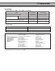
■ CONNECTOR PIN ASSIGNMENT
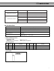
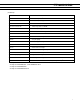
1. Connector for power supply (CN10)
Part number : B6P-VH (J.S.T)
Mating connector part number : VHR-6N (J.S.T) or equivalent
No. Signal I/O Contents No. Signal I/O Contents
1VCC — Power supply for logic (+5 V) 2 GND — GND (5 V, 24 V common)
3 GND — GND (5 V, 24 V common) 4 GND — GND (5 V, 24 V common)
5VDD — Power for head/motor (+24 V) 6 V DD — Power for head/motor (+24 V)
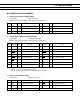
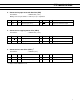
2. Connector for thermal head drive (CN8)
Part number : B16B-PH-K-S (J.S.T)
Mating connector part number : PHR-16 (J.S.T) or equivalent
No. Signal I/O Contents No. Signal I/O Contents
1 VDH O Power for head (+24 V) 2 VDH O Power for head (+24 V)
3
GND (VDH)
— Head GND 4
GND (VDH)
— Head GND
5 STB1 O Print enable signal 1 6 STB2 O Print enable signal 2
7 STB3 O Print enable signal 3 8 TMP I Temperature detection signal
9 STB4 O Print enable signal 4 10 LAT O Print data latch signal
11 STB5 O Print enable signal 5 12 5 VH O Power for logic (+5 V)
13 HCLK O Data transmission clock 14 HD O Print data output signal
15
GND (VDH)
— Head GND 16 VDH O Power for head (+24 V)
Notes:
• Symbol “——” means a negative logic signal.
• “I” or “O” means a signal direction from the interface board side.
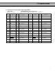
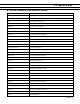
3. Connector for Sensor (CN3)
Part number : B5B-PH-K-S (J.S.T)
No. Signal I/O Contents No. Signal I/O Contents
1 +5 V — Power for logic (+5 V) 2 PES I Paper end detect signal
3
GND (5 V)
— Logic GND 4 +5 V — Power for logic (+5 V)
5 HUP I Head-up detect signal