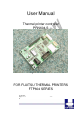
User Manual Thermal printer controller PRN604-S FOR FUJITSU THERMAL PRINTERS FTP604 SERIES 12-02-2003 Page 1-1 of 51 - 1-1 -
VERSION HISTORY Version 0.9 0.91 0.92 0.93 Date 020712 021022 030111 030125 Init BB BB BB BB Status Draft Pre-release Pre-release Pre-release Description First release Second pre-release Third pre-release Connector updated Copyright 1999-2003 by I/F-COM A/S. All rights reserved. I/F-COM A/S has prepared this manual for use by I/F-COM A/S’ customers.
• extremely high reliability is required. If you are considering such applications, please consult our customer service department. There is a general possibility of component failure. Every effort has been made to improve product quality but such failures cannot be completely excluded. Please assume that such failure may occur before using this printer. We would urge that these specifications should be thoroughly understood and the printer used safely in your company or associated organisation.
1 SYSTEM DESCRIPTION ............................................................................................1-7 2 INSTALLATION ...........................................................................................................2-7 2.1 UNPACKING ..............................................................................................................2-7 2.2 LABELS .....................................................................................................................2-7 2.
3.8.15 3.8.16 3.8.17 3.8.18 3.8.19 3.8.20 3.8.21 3.8.22 3.8.23 3.8.24 3.8.25 3.8.26 3.8.27 3.8.28 3.8.29 3.8.30 3.8.31 3.8.32 3.8.33 3.8.34 3.8.35 3.8.36 3.8.37 3.8.38 3.8.39 3.8.40 3.8.41 3.8.42 4 MAINTENANCE.........................................................................................................4-32 4.1 4.2 5 DAILY USE ..............................................................................................................4-32 STORE/TRANSPORT .......................................
7.1 SEIKO COMPATIBLE COMMAND SET (OPTIONAL) .....................................................7-41 7.1.1 Escape sequences, overview...........................................................................7-41 7.2 FUJITSU COMPATIBLE COMMAND SET (OPTIONAL) ..................................................7-42 7.2.1 Escape sequences, overview...........................................................................7-42 7.3 APS COMPATIBLE COMMAND SET (OPTIONAL) ...........................................
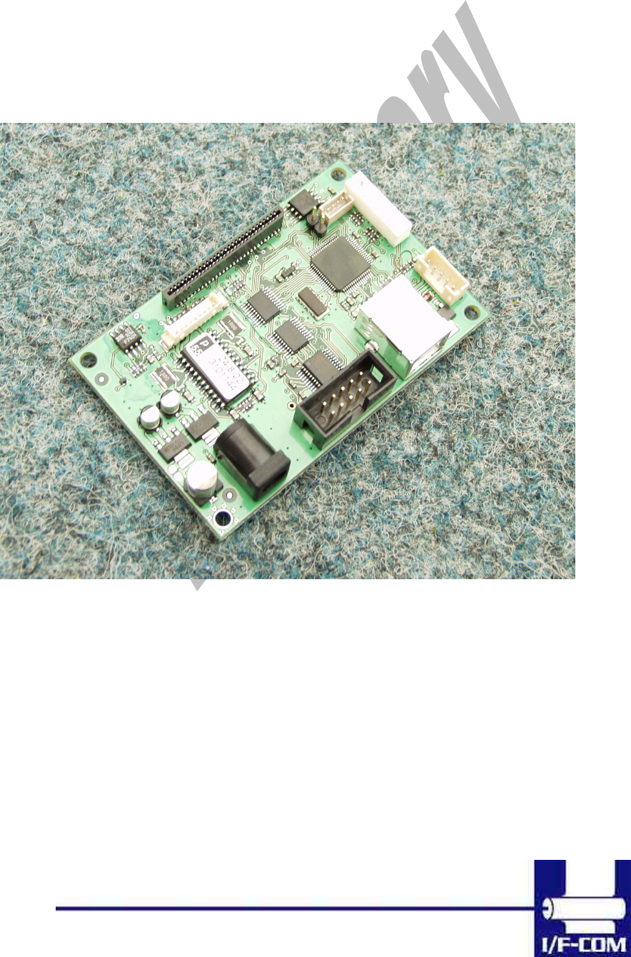
1 SYSTEM DESCRIPTION This reference manual describes the specifications, functions, and operating procedures for the PRN604-SInterface Board. The PRN604-S is an interface board for the FTP604 series printer mechanisms. This reference manual also describes the print operation of the FTP604. Read this reference manual thoroughly before using the PRN604-S. PRN604-S is designed for the following Fujitsu printers: FTP-624MCLxxx FTP-634MCLxxx FTP-644MCLxxx PRN604-S consists of an interface board.
2.3 Installation PRN604-Sis fastened in the product by 4 M3.3 screws. The cables (for the thermal head, the stepper-motor and detector) are placed in the thermal printer connector on the PCB. 1 Mounting hole is grounded. See drawing for more details. (a) To connect or remove the connector, always turn off the power in advance. If the connector is connected or removed while the power to the printer is on, errors may occur. (b) The connector of each cable must be correctly locked and connected.
2.5 Settings Following below description can change default settings. Baud rate is default 115.200, however standard PC´s today cannot handle this Baud rate. Windows OS does not support speed higher than 115.200 Baud, even when setup menus can be set to higher speed. In order to obtain higher speed you need to install 3rd part utility program on PC. Please visit www.if-com.com for further information. 1. Turn off power 2. Press Key 1 low while power up. Board is now in setting mode.
i. j. k. l. m. n. 12-02-2003 Page 2-10 of 51 iii. 448 dots iv. 512 dots v. 576 dots vi. 640 dots vii. 832 dots viii. 1152 dots Key 1 function 1. Input key 2. LED output 3. Label detect 4. Black mark detection 5. Paper near end function 6. Paper jam function a. Stop printer b. Send data to host Key 2 function 1. Input key 2. LED output 3. Label detect 4. Black mark detection 5. Paper near end function 6. Paper jam function a. Stop printer b. Send data to host Paper select i. Paper 1 ii. Paper 2 iii.
o. p. q. r. s. t. 12-02-2003 Page 2-11 of 51 v. 10 mm vi. 20 mm vii. 30 mm viii. 50 mm Grey scale printing i. On ii. Off Acceleration i. Slow ii. Medium iii. Fast iv. Disable Printing speed i. 25% ii. 50% iii. 75% iv. 100% v. Disable Burn strobe dark i. 1 ii. 2 iii. 3 iv. 4 v. 5 vi. 6 vii. 7 viii. 8 ix. 9 Burn strobe light i. -1 ii. -2 iii. -3 iv. -4 v. -5 vi. -6 vii. -7 viii. -8 ix. -9 Output i. Cash drawer output 1. Solenoid time 0,2 sec. 2. Solenoid time 0,5 sec. 3. Solenoid time 0,7 sec. 4.
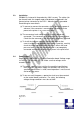
ii. Winding motor Settings will be effective upon turn off and on. 2.6 Serial Input/Output If BUSY control is selected: When 236 bytes of data have been stored in the input buffer, the SBUSY signal becomes high to request that the computer temporarily stop sending data. When the amount of data stored in the input buffer becomes 235 bytes or less, the SBUSY signal changes to low to request that the host device continue data transfer.
switches. However, the hardware error code (a) has the same conditions as those for parallel input. When transferring data, data control by SBUSY and Xon/Xoff is not executed and the data is transferred with no conditions. All of the transmission conditions of serial data transfer for sending hardware error codes are fixed at the selection of parallel input as follows: 2.6.1.1 Serial input/output port Serial data output (TxD) When Xon/Xoff control is selected, the Xon/Xoff signal is output.
2.7 THERMAL HEAD CONTROL Data Transfer to the Thermal Head The PRN604-S transfers one dot line of data at 6 Mbps synchronized with the CLOCK signal. The data is transferred in order to the shift register inside the thermal head from the left (when facing the paper feed direction). The transferred data is then transferred by the head latch signal to the latch register inside the thermal head. Turning on the head strobe signal initiates printing of one dot line of data on the thermal paper. 2.7.
When the maximum number of activated dots is 128 dots, and all of the dots are driven, as shown in 2.7.3 Head Control Circuit The PRN604-S has a function for measuring the resistance of the thermal head connected to the FTP604. The PRN604-S measures the resistance of the thermal head and detects the errors at initialisation. Based on the measurement, the PRN604-S determines how much energy to apply. No adjustment is needed for replacing the FTP604 to get the best printing. 2.7.
Specifications Default settings Interface Serial RS232C, USB or IRDA 115.200 baud, 8 data bit, none parity, 1 stop bit, hardware handshake.Baud rate can be changed by software. Data format serial USB Printer class specification. Data format USB http://www.usb.org/developers/data/devclass/usbprint11.pdf IRDA (Ircomm specifications) Data format IRDA http://www.irda.org/standards/pubs/ircomm10.pdf Command set I/F-com Transmission to host Requested status etc.
3 Function 3.1 General Notice, when data is sent from the external equipment to the printer controller, all data has to be sent as binary file. If data is being sent as a character file, and some data in the file is equal to EOF, the rest will not be received. 3.2 Serial communication. Standard communication is; Baud rate; 115.200 Baud Data bits = 8 Stop bits = 1. Parity = None Flow control = Hardware handshake Baud rate can be changed by changed by a software command. 3.3 USB communication.
3.5 Firmware upgrade. If firmware needs to be changed, alternative firmware can be downloaded. Please contact I/F-COM for firmware upgrade or changes. The steps to download an alternative firmware in DOS are the following. These steps only work for a serial connection, look further down how to do it with USB. 1. Power the system off. 2. Disconnect printer. 3. Short circuit the pins “upgrade firmware” 4. Turn on printer 5.
3.7 Character design The following figures describes the design of different types of characters (small): 3.7.1 Normal Character. 3.7.
3.7.3 Underline When underline characters are printed the last line in the character matrix will be marked. 3.7.4 Bold When bold characters are printed the character is or with itself shifted right. 3.7.5 Reverse When reverse characters are printed the character matrix will be negated. 3.7.6 Italic. When Italic characters are printed every line will be shifted the following number of dots to the right: (Line number from bottom)/4 3.7.7 Font sizes.
3.8 I/F-COM simple command set. The following commands are use when communicating with the printer controller. All other commands is ignored 3.8.1 Small Font [Name] [Format] [Description] 3.8.2 Low Font [Name] [Format] [Description] 3.8.3 Narrow Font [Name] [Format] [Description] 3.8.4 Normal Font [Name] [Format] [Description] 3.8.5 Wide Font [Name] [Format] 12-02-2003 Page 3-21 of 51 Small Font (8x12) ASCII NUL Hex 00 Decimal 0 Chooses small font from the current print position.
[Description] 3.8.6 High Font [Name] [Format] [Description] 3.8.7 Large Font [Name] [Format] [Description] 3.8.8 Xlarge Font [Name] [Format] [Description] 3.8.9 Line Feed [Name] [Format] [Description] 3.8.10 Barcode on [Name] [Format] [Type] 12-02-2003 Page 3-22 of 51 Hex 04 Decimal 4 Chooses wide font from the current print position. High Font (16x56) ASCII ENQ Hex 05 Decimal 5 Chooses high font from the current print position.
[Description] Turns the barcode on until non-barcode character received. [Barcode char.] Space , $ , % , * , + , - , . , / , 0-9 , A-Z [Notes] The barcode 39 must start and end with the character ‘*’. This character is the start and stop character in barcode 39, and the ‘*’ can only be used as start and end character. If the barcode length exceeds the paper size the last barcode character will not be written as barcode. In that case the barcode cannot be read because the last character will not be ‘*’ 3.8.
[Description] 3.8.16 Underline on [Name] [Format] [Description] 3.8.17 Bold off [Name] [Format] [Description] 3.8.18 Bold on [Name] [Format] [Description] Hex 10 Decimal 16 This command will switch off underline printing Underline on ASCII DC1 Hex 11 Decimal 17 This command will switch on underline printing Bold off ASCII DC2 Hex 12 Decimal 18 This command will switch off bold printing Bold on ASCII DC3 Hex 13 Decimal 19 This command will switch on bold printing 3.8.
3.8.21 Initialise Printer [Name] Initialise [Format] ASCII SYN Hex 16 Decimal 22 [Description] When the printer controller receives this byte a reset of the printer will be initialised. This command can be treated even if buffer is full. 3.8.22 Request Software version [Name] Request software version [Format] ASCII ETB Hex 17 Decimal 23 [Description] When the printer controller receives this byte the software version will be transmitted. This command can be treated even if buffer is full. 3.8.
[Description] Decimal 25 When the printer controller receives this byte the digital value of the head voltage will be transmitted. This command can be treated even if buffer is full 3.8.25 Request Temperature [Name] Request Temperature [Format] ASCII SUB Hex 1A Decimal 26 [Description] When the printer controller receives this byte the digital value of the head temperature will be transmitted. This command can be treated even if buffer is full 3.8.
If n > 1 and < 254 then the output will be turned on in n/4.096msec, and then turned off again. If n = 255, then the output will be turned on. 3.8.29 Automatic sending status [Name] [Format] [Description] Automatic sending status ASCII ESC a Hex 1B 61 Decimal 27 97 When this command is sent once, then the board will transmit the status every time that it change state. 3.8.
[Description] 3.8.33 Save data to board [Name] [Format] [Description] 3.8.34 Change dot size [Name] [Format] [Description] 3.8.35 Change form feed length [Name] [Format] [Description] 3.8.36 Change baud rate [Name] [Format] 12-02-2003 Page 3-28 of 51 Decimal 27 100 This command will enable that the boards save values to the flash, this is made to ensure that a wrong transmission not will change settings in the board, remember to send the command “Saving data to board”, to actual save the data.
[Description] 3.8.37 Change form feed time [Name] [Format] [Description] 3.8.38 Feed Paper [Name] [Format] [Range] [Description] Decimal 27 104 n N represents the new baud rate, legal values for n = 1 to 255. The baud rate is calculated as 921600/n = new baud rate. For instance 921600/8 = 115200baud.
3.8.40 Graphic data – non compressed [Name] Graphic data – non-compressed [Format] ASCII US d1,d2,..,dX Hex 1F d1,d2,..,dX Decimal 31 d1,d2,..,dX [Range] n: [0;255] X=54 for FTP624MCLxxx, X=72 for FTP634MCLxxx, [Description] When the printer controller receives this command the X graphic bytes (d1-dX) will be printed in one dot line. The MSB in d1 is the left most dot and the LSB in dX is the right most dot. 3.8.41 Graphic data – compressed [Name] Graphic data – compressed [Format] ASCII Y d1,d2,..
NUL SOH STX ETX EOT ENQ ACK BEL LF VT FF SO SI DLE DC1 DC2 DC3 DC4 NAK SYN ETB CAN EM SUB GS+n RS+n US+d1..
4 Maintenance 4.1 Daily use Printer and interface board must be switch off while in idle mode. 4.2 Store/Transport The product has to be stored under ESD safe conditions, and to be packed safely during transportation.
5 Specifications 5.1 Electrical Data Voltage: 6-8,5VDC Current: Maximum head current:Numbers of active dots * Vhead 150+/-15% Maximum motor current: Power up sequence: Power down sequence: 1000mA max. 10 msec. 10 – 90% Voltage applied max. 10 msec. 90 – 10% Voltage applied 5.2 Mechanical Data Dimensions: Length, width, height: 77 mm* 50 mm * max. 15 mm Including connectors. Vibration: 100G XYZ Shock: 100G XYZ 5.
ESD: 4 kV contact discharge against parts exposed to contact at normal use. 8 kV air discharge. 5.5 Temperature Test Temperature shock: (no voltage applied) -28°C to +100°C at 1 sec. 100 times: no damage.
6 Connector Pin Assignment 6.1.1 Motor connector Connector CN1: 5501-4S Mating connector part number: TBA Pin 1 2 3 4 Function /MB MB /MA MA 6.1.
6.1.3 Thermal Head connector FTP634MCLxxx and FTP644MCLxxx Mating connector: TBA Connector CN4: JS1125-11 Pin 1 2 3 4 5 6 Function /ST5 /ST6 /ST7 /ST7 /CLK /LAT Pin 7 8 9 10 11 Function DI GND GND VH VH Pin 6 7 8 9 10 Function /ST1 /ST2 /ST3 /ST4 +5V 6.1.
6.1.5 IRDA connector IRDA connector CN7: B4B-ZR Mating connector part number: TBA Pin Function 1 +5V 2 TX 3 RX 4 GND 6.1.
The LED will show these conditions LED Off Flash 1Hz Flash 2Hz On Error No Error Paper near end Paper jam Both paper jam and near end 6.1.7 Power connector Power connector CN10: KLD-0202-B Mating connector TBA Pin 1 2 Function GND +8.5V Pin 3 4 Function GND +8.5V 6.1.8 USB connector USB connector CN8: UBBR-04SW11 Mating connector: TBA Pin Function 1 2 N.C. USB- 6.1.
Pin 1 Function GND 2 Vcoil, Max 24V 3 Coil, max 1A 4 5 Anode Cathode Using output as cash drawer solenoid time must be set. By default solenoid time is 0,5 sec. Using output for winding motor, connector must be applied. Upon feeding with motor the winding motor also turns. Please see manual for winding motor for more information 6.1.
6.
7 Appendix 7.1 Seiko compatible command set (optional) 7.1.1 Escape sequences, overview. CR ESC+ ‘ J ’ +n ESC+ ‘ j ’ +n ESC+ ‘ 2 ’ ESC+ ‘ 0 ’ ESC+ ‘A’+n or ESC+ ‘3’+n ndot ESC+ SP+n ESC+ ‘ s ’+nl+nr ESC+ ‘ U ’+n DC2+ ‘ Y’ +n ESC+ ‘ - ’ +n SO DC4 ESC+ ‘ W ’+n ESC+ ‘ w ’+n ESC+ ‘ I ’+n DC2+ ‘ F ’+n ESC+ ‘ t ’+n ESC+ ‘ & ’ + s + e+ ESC+ ‘ % ’ + n DC2+ ‘ D ’+n ESC+ ‘+’ + k1 + k2+ FS+ ‘ 2 ’ + k1 + k2+ ESC+ ‘ K ’ or FS+ ‘ & ’ ESC+ ‘ H’ or FS+ ‘.
DC2+ ‘ P ’ + s + e+ x + y + DC2+ ‘ O ’+n DC2+ ‘ Q ’ DC3+ ‘ A ’ DC3+ ‘ B ’ DC3+ ‘ V ’ + DC3+ ‘ D ’+nl+nh DC3+ ‘ L ’+ml+mh+nl+nh DC3+ ‘ F ’+n1+n2 Font Data Option Font Define Option Font Select/Deselect Option Font Clear Ruler Line Buffer A Ruler Line Buffer B Image Data Ruler Line Image Define Ruler Line by Dot Define Ruler Line by Line Define Ruler Line with Repeating Pattern Ruler Line ON Ruler Line OFF Print One Dot Line after Printing Line Buffer Data Ruler Line Buffer Clear Continuous Ruler Line Contro
ESC @ ESC A+n ESC C+n ESC D+[n]k+NUL ESC J+n ESC K+n ESC R+n ESC c+1+n ESC d+n ESC e+n ESC s+n ESC t+n ESC {+n FS 9+n GS < GS A+m+n GS E+n GS V+n+m GS e+n+m GS h+n GS k+m+n+[d]k GS w+n FS *+n1+n2+[n]k GS &+m+x+y1+y2+[n]k GS '+m+n FS E+n ESC V+n GS a+n FS r+n ESC EM+n ESC X+n+m Line Feed [Name] [Format] 12-02-2003 Page 7-43 of 51 Line Feed ASCII Hex Decimal Printer initialisation Line spacing setting Page length (number of lines) setting Horizontal tab position setting Printing and minimum-pitch-unit pape
[Description] When the printer controller receives this byte the text data in the buffer will be printed Horizontal tab [Name] Horizontal tab [Format] ASCII HT Hex 0A Decimal 10 [Description] When the printer controller receives this byte the text data in the buffer will be printed 12-02-2003 Page 7-44 of 51 - 7-44 -
7.3 APS compatible command set (optional) 7.3.1 Escape sequences, overview.
Description: Format: Comments: Example: GS D n Description: Format: Comments: Set printing speed / Maximum peak current/ Dynamic division <1Dh> <2Fh> n=1 to 32: (Default n=5) Software programmable consumption (Dynamic division). The maximum number of black dots which are simultaneously heated is (n+1) x 8. In Default Mode, n = 5. n=5 Maximum black dots heated: (5+1)*8=48. Printer Peak consumption @5V: (0.3A (Stepper Motor) + 5*48/160) = 1.8A 160 Ohms is the dot resistance.
7.4 ESC/POS compatible command set (optional) 7.4.1 Escape sequences, overview.
ESC d n ESC i ESC p m t1 t2 ESC t n ESC u n ESC v ESC { n GS ! n G S $ nL nH GS * x y [d] x*y *8 GS / m GS : GS B n GS H n GS I n GS L nL nH GS P x y GS V m n GS W nL nH GS \ nL nH GS ^ r t m GS a n GS b n GS f n GS h n GS k m d1…dk NUL GS k m n d1…dn GS r n GS w n 12-02-2003 Page 7-48 of 51 Print and feed n lines Partial cut Cash drawer Output Select character Code table Transmit peripheral device status Transmit paper sensor status Turns on/off upside-down printing mode Select character size Set absolut
7.
Please note that distance from top of sensor to paper must be Min 0,5mm and Max 1,00mm 12-02-2003 Page 7-50 of 51 - 7-50 -
RED RED WHITE BLACK RED WHITE BLACK Example showing how to connect PRS600 to AUX Input connector CN4 on PRN604-S standard board.