Thin Client Operating Manual FUTRO S720 FUTRO S920 ESPRIMO A525-L
Thank you for buying an innovative product from Fujitsu. Latest information about our products, useful tips, updates etc. is available on our website: "http://www.fujitsu.com/fts/" You can find driver updates at: "http://support.ts.fujitsu.com/download" Should you have any technical questions, please contact: our Hotline/Service Desk (see Service Desk list or from the Internet at: "http://support.ts.fujitsu.
Published by / Contact address in the EU Fujitsu Technology Solutions GmbH Mies-van-der-Rohe-Straße 8 80807 Munich, Germany "http://www.fujitsu.com/fts/" Copyright © Fujitsu Technology Solutions GmbH 2015. All rights reserved. Publication Date 07/2015 Order No.
FUTRO S720 FUTRO S920 ESPRIMO A525-L Operating Manual Validity of the Reference Manual 5 Ports and operating elements 6 Important notes 10 Getting started 16 Operation 25 System expansions 29 Technical data 61 Index 63
Remarks Information on the product description meets the design specifications of Fujitsu and is provided for comparison purposes. Several factors may cause the actual results to differ. Technical data is subject to change without prior notification. Fujitsu rejects any responsibility with regard to technical or editorial mistakes or omissions.
Contents Contents Validity of the Reference Manual . . . . . . . . . . . . . . . . . . . . . . . . . . . . . . . . . . . . . . . . . . . . . . . . . . . . . . . Notational conventions . . . . . . . . . . . . . . . . . . . . . . . . . . . . . . . . . . . . . . . . . . . . . . . . . . . . . . . . . . . . . . . . . . 5 5 Ports and operating elements . . . . . . . . . . . . . . . . . . . . . . . . . . . . . . . . . . . . . . . . . . . . . . . . . . . . . . . . . Front view . . . . . . . . . . . . . . . . . .
Contents System expansions . . . . . . . . . . . . . . . . . . . . . . . . . . . . . . . . . . . . . . . . . . . . . . . . . . . . . . . . . . . . . . . . . . . . Overview of optional system components . . . . . . . . . . . . . . . . . . . . . . . . . . . . . . . . . . . . . . . . . . . . . . . . . Possible combinations for the FUJITSU Thin Client FUTRO S920 . . . . . . . . . . . . . . . . . . . . . . . Information about boards . . . . . . . . . . . . . . . . . . . . . . . . . . . . . . . . . . . . . . . .
Validity of the Reference Manual Validity of the Reference Manual This Reference Manual is valid for the following systems: • • • FUJITSU Thin Client FUTRO S720 FUJITSU Thin Client FUTRO S920 FUJITSU Desktop ESPRIMO A525-L Notational conventions Pay particular attention to text marked with this symbol. Failure to observe these warnings could pose a risk to health, damage the device or lead to loss of data.
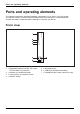
Ports and operating elements Ports and operating elements Ports This chapter presents the individual hardware components of your device. This will provide you with an overview of the ports and operating elements on the device. Please familiarise yourself with these components before starting to work with your device.
Ports and operating elements Rear view PCIe slot PCIslot Audioinput DCinputconnector Audiooutput USBports Serialport Monitorport PS/2keyboardport Installationopening PS/2mouseport LANsocket SecurityLock 15 14 13 1 2 3 4 12 5 11 6 10 7 9 8 1 = Socket for Power over Ethernet module (optional) 2 = Audio output (Line Out) 3 = PS/2 keyboard port 4 = USB ports 5 = USB ports 6 = DisplayPort 7 = DVI-I monitor port 8 = DC input jack (DC IN) 9 = Security Lock device 10 = Serial port 11 = Serial port (onl
Ports and operating elements Security Lock device Using the Security Lock device and the Kensington Lock cable (steel cable, accessory) you can protect your device against theft. Please consult the manual for your Security Lock. Your device has a Security Lock device on the rear side. If you are using the VESA sub-adapter, first connect the Kensington Lock Cable to the Security Lock device and then mount your device on the VESA sub-adapter.
Ports and operating elements ► Insert the USB covers in the USB ports on the rear side of the device and push the USB covers in firmly. In the BIOS Setup, under Advanced - USB Port Security, you can also deactivate the USB ports, in order to limit the use of USB devices.
Important notes Important notes Notes Importantnotes In this chapter you will find information regarding safety which it is essential to take note of when working with your device. Safety notes Note Safetynotes Please follow the safety notes provided in the "Safety/Regulations" manual as well as the safety notes given below. When installing and operating the device, please observe the notes on ambient conditions in "Technical data ", Page 61 and the instructions in "Getting started", Page 16.
Important notes Important notes on preparing your FUTRO S720/S920 or ESPRIMO A525-L for use via the Power over Ethernet module With the aid of the Power over Ethernet module, you can operate the FUTRO S720/S920 or the ESPRIMO A525-L over the LAN without any additional power connection. You will need a suitable network infrastructure for this. To operate the FUTRO S720/S920 or the ESPRIMO A525-L via the Power over Ethernet module, midspan devices conforming to IEEE 802.
Important notes Transporting the device Retransportation Transportation Device, Transport all parts separately in their original packaging or in a packaging which protects them from knocks and jolts, to the new site. Do not unpack them until all transportation manoeuvres are completed. If the device is brought from a cold environment into the room where it will be used, condensation may occur.
Important notes Energy saving, disposal and recycling Drivers& Recycling Energysaving Disposal User DocumentationDVD UtilitiesDVD You can find information on these subjects in chapter "Activating power saving mode (FUJITSU Thin Client FUTRO only)", Page 27, on the Recovery DVD or on our website ("http://www.fujitsu.com/fts/about/fts/environment-care/").
Important notes FCC Compliance Statement If the device complies with the FCC regulations, the FCC sign can be found on the type rating plate. FCC Class B Compliance Statement DOC (INDUSTRY CANADA) NOTICES Notice to Users of Radios and Television: This class B digital apparatus complies with Canadian ICES-003. The following statement applies to the products covered in this manual, unless otherwise specified herein. The statement for other products will appear in the accompanying documentation.
Important notes CE marking The shipped version of this device meets the requirements of EU directives 2004/108/EC "Electromagnetic compatibility", 2006/95/EC "Low voltage directive", 2011/65/EU "RoHS directive" and 2009/125/EC "Ecodesign directive". For this purpose, please also note the special information concerning the "Ecodesign directive" for the FUTRO systems (see "Energy saving, disposal and recycling", Page 13).
Getting started Getting started Gettingstarted Please observe the safety information in the "Important notes", Page 10 chapter. Setting up the device In order to ensure that the casing is sufficiently ventilated and to prevent overheating, the device must only be operated with the base foot attached. If the device is to be built-in, adequate ventilation must be assured.
Getting started 3 3 3 1 1 3 2 2 ► Hook the feet into each of the openings provided for this in the casing (1).
Getting started ► Stand the device on the feet. ► If necessary, reconnect any cables that were previously disconnected.
Getting started Horizontal operating position If you wish to operate the device in the horizontal operating position, use the two feet supplied for horizontal operation. Only mount the feet on the device side shown in the diagrams. Proceed as follows to prepare the device for the horizontal operating position: Base feet Operatingposition,horizontal Horizontaloperatingposition ► Disconnect the cables if required. ► Lay the device on its right side as shown, on a stable, flat and clean surface.
Getting started To protect your device against unauthorised removal of the feet, the feet can also be secured with two screws each, of type M2.5x5 mm. These are not included in the delivery scope. ► Secure the feet with the screws (3). ► Stand the device on the feet. ► If necessary, reconnect any cables that were previously disconnected.
Getting started Connecting external devices Read the documentation on the external device before connecting it. To ensure that your device works properly, use either only the supplied connection cable or only other connection cables of equivalent quality. With the exception of USB devices, always remove all power plugs before connecting external devices! Do not connect or disconnect cables during a thunderstorm. Always take hold of the actual plug. Never unplug a cable by pulling the cable itself.
Getting started Connecting a monitor ► Follow the instructions contained in the monitor manual to prepare the monitor for operation (e.g. connecting cables). ► Connect the data cable to the required monitor port on your device. ► Plug the monitor power cable into the grounded mains outlet. Monitor, Connecting the mouse You can connect a USB mouse or a PS/2 mouse to your device. Connecting, Mouse, Connecting a USB mouse ► Connect the USB mouse to one of the USB ports on the device.
Getting started Connecting external devices to the serial interface Devices, Externaldevices, Serialinterface, Serialinterface External devices can be connected to the serial interface (e.g. a printer or modem). ► Connect the data cable to the external device. ► Connect the data cable to the corresponding serial interface. For an exact description of how to connect external devices to the corresponding port, please see the external device documentation.
Getting started Connecting microphone, headphones, line-out and line-in devices Line-outdevices Headphones Microphone ► ► ► ► Connect Connect Connect Connect the microphone to the microphone port. the headphones to the headphones port. line-out devices to the audio output. the external line-in devices to the audio input. Connecting the device to the network (LAN) LAN ► Connect the 10/100/1000 Base T network cable to the RJ45 LAN port.
Operation Operation Switch the device on ► If necessary, switch the monitor on (see the operating manual for the monitor). ► Press the ON/OFF switch on the front of the device. The power indicator lights up and the device starts.
Operation Scout Enterprise™ – The management solution for Thin Clients Basic functionalities • • • Multi-administrator policy Simple scalability and high availability Optimal support of complex organisations Asset management functions • • • • • Display of serial number and connected monitors Illustration of update history Flexible licence management Display of device, hardware and network information Display of installed or connected components, such as mainboard, memory, display adapters, monitors and
Operation Switching off the device ► Shut down the operating system in the proper way. In Windows: from the Start menu select the Shut Down option. ► If the operating system does not automatically switch the device into energy-saving mode or switch it off, press the ON/OFF switch. Warning, this could lead to a loss of data! If the device is switched off, it consumes a minimum of energy. Monitor, Device, The ON/OFF switch does not disconnect the device from the mains voltage.
Operation BIOS Update When should a BIOS update be performed? Fujitsu Technology Solutions makes new BIOS versions available to ensure compatibility with new operating systems, new software or new hardware. In addition, new BIOS functions can be integrated. A BIOS update should also always be performed if there is a problem that cannot be solved using new drivers or new software. Where can I obtain BIOS updates? You can find the BIOS updates on the Internet at "http://support.ts.fujitsu.com/".
System expansions System expansions System expansion Device, Upgrades, Servicing Components Repairs to the device must only be performed by qualified technicians. Incorrect repairs may greatly endanger the user (electric shock, fire risk) and will invalidate your warranty. After consulting the Hotline/Help Desk, you may remove and install the components described in this manual yourself.
System expansions Overview of optional system components The following optional system components can be installed in the various device types: System component Hard disk FUJITSU Thin Client FUTRO S720 — SmartCard reader Speaker Power over Ethernet module Third serial port FUJITSU Thin Client FUTRO S920 — optional optional optional optional optional optional — — — — optional* optional* optional* optional* Parallel port PCIe dual serial card PCIe ATI V3900 FUJITSU Desktop ESPRIMO A525-L Installed w
System expansions Information about boards Take care with the locking mechanisms (catches and centring pins) when you are replacing boards or components on boards. Note that some components on the mainboard may be very hot if the device was in use shortly before the casing was removed. To prevent damage to the board or the components and conductors on it, please take care when you insert or remove boards. Make sure expansion boards are inserted straightly.
System expansions Opening the casing Device, Casing, ► Switch the device off. The device must not be in power-saving mode. Please observe the safety information in "Important notes", Page 10. Disconnect the mains plug from the mains outlet. Only insert the power plug after you have closed the casing. Open the casing carefully because there are WLAN cables that lead from the casing cover to the system and these may break if the casing is opened carelessly. ► Remove any connected wires which are in the way.
System expansions Adding memory Removing Mainmemory Memorymodule System expansion memory If you want to remove or add memory, proceed as follows: Please observe the safety information in chapter "Important notes", Page 10. Only use memory expansions for notebooks: 1 GByte and 2 GByte modules DDR3-1333 SO DIMM or DDR3-1600 SO DIMM. Never use force when installing or removing a memory extension. Make sure that foreign objects do not fall into the memory extension compartment. Individual components (e.g.
System expansions Installing and removing the SmartCard reader (FUJITSU Thin Client FUTRO S920 only) If you are also installing the optional loudspeaker, install the SmartCard reader before the loudspeaker. Installing the SmartCard reader SmartCardreader If not already installed, you can fit a SmartCard reader. ► Open the casing (see "Opening the casing", Page 32). ► If a PCIe board is installed, you must remove the cross piece and PCIe board (see "Removing the board", Page 58).
System expansions 2 1 ► Place the carrier for the SmartCard reader in the casing (1). ► Fasten the carrier with the screw (2).
System expansions 2 4 2 1 3 ► Place the SmartCard reader on the carrier with the component side facing downwards, in the direction of the arrow (1). ► Fasten the SmartCard reader onto the carrier with the screws (2). ► Connect the cable to the SmartCard reader (3) and to the connector on the mainboard (4). ► When required, reinstall the cross piece and the PCIe board (see "Installing the board", Page 56). ► Close the casing (see "Closing the casing", Page 60).
System expansions Removing the SmartCard reader SmartCardreader ► Open the casing (see "Opening the casing", Page 32). ► If a PCIe board is installed, you must remove the cross piece and PCIe board (see "Removing the board", Page 58). 3 2 3 4 1 ► ► ► ► ► Disconnect the cable from the SmartCard reader (1) and from the mainboard (2). Undo the screws (3). Lift the SmartCard reader from the carrier (4). When required, reinstall the cross piece and the PCIe board (see "Installing the board", Page 56).
System expansions Information about installing and removing a speaker (optional) You can install an additional speaker in your device: • • 38 For FUJITSU Thin Client FUTRO S720 / FUJITSU Thin Client FUTRO S920, see chapter "Installing and removing a speaker: FUJITSU Thin Client FUTRO S720 / FUJITSU Thin Client FUTRO S920", Page 39 For FUJITSU Desktop ESPRIMO A525-L, see chapter "Installing and removing a speaker: FUJITSU Desktop ESPRIMO A525-L", Page 41 Fujitsu
System expansions Installing and removing a speaker: FUJITSU Thin Client FUTRO S720 / FUJITSU Thin Client FUTRO S920 Installing the loudspeaker Loudspeaker The required hexagon head bolts are included in the delivery scope of the loudspeaker. ► Open the housing (see "Opening the casing", Page 32). ► If a PCIe board is installed, you must remove the cross piece and PCIe board (see "Removing the board", Page 58). 1 1 4 ► Secure the hexagon head bolts provided into the screw holes (1).
System expansions 1 1 2 ► ► ► ► ► Insert the loudspeaker into the housing as illustrated. Secure the loudspeaker with the screws (1). Connect the loudspeaker cable to the connector on the mainboard (2). When required, reinstall the cross piece and the PCIe board (see "Installing the board", Page 56). Close the housing (see "Closing the casing", Page 60). Ensure that the cables are not trapped between the housing and the components.
System expansions Removing the loudspeaker Loudspeaker ► Open the housing (see "Opening the casing", Page 32). ► If a PCIe board is installed, you must remove the cross piece and PCIe board (see "Removing the board", Page 58). 2 2 1 ► ► ► ► ► Disconnect the loudspeaker cable from the mainboard (1). Undo the screws (2). Lift the loudspeaker out of the housing. When required, reinstall the cross piece and the PCIe board (see "Installing the board", Page 56).
System expansions Installing a speaker Removing a hard disk Harddisk ► Open the housing (see "Opening the casing", Page 32). 2 1 1 ► Disconnect the cables from the hard disk (1). ► Undo the screw (2).
System expansions 2 1 2 ► Slide the hard disk in the direction of the arrow (1). ► Lift the hard disk out of the casing (2).
System expansions Installing the loudspeaker Loudspeaker The required hexagon head bolts are included in the delivery scope of the loudspeaker. 1 1 4 ► Secure the hexagon head bolts provided into the screw holes (1).
System expansions 1 1 2 ► Insert the loudspeaker into the housing as illustrated. ► Secure the loudspeaker with the screws (1). ► Connect the loudspeaker cable to the connector on the mainboard (2).
System expansions Installing a hard disk Loudspeaker 2 2 1 ► Insert the hard disk into the casing (1). ► Slide the hard disk in the direction of the arrow (2).
System expansions 1 2 2 ► Secure the hard disk with the screw (1). ► Connect the cables to the hard disk (2). ► Close the housing (see "Closing the casing", Page 60). Make sure that the cables are not trapped between the casing and the components.
System expansions Removing a speaker Removing a hard disk Harddisk ► Open the housing (see "Opening the casing", Page 32). 2 1 1 ► Disconnect the cables from the hard disk (1). ► Undo the screw (2).
System expansions 2 1 2 ► Slide the hard disk in the direction of the arrow (1). ► Lift the hard disk out of the casing (2).
System expansions Removing the loudspeaker Loudspeaker 2 2 1 ► Disconnect the loudspeaker cable from the mainboard (1). ► Undo the screws (2). ► Lift the loudspeaker out of the housing.
System expansions Installing a hard disk Loudspeaker 2 2 1 ► Insert the hard disk into the casing (1). ► Slide the hard disk in the direction of the arrow (2).
System expansions 1 2 2 ► Secure the hard disk with the screw (1). ► Connect the cables to the hard disk (2). ► Close the housing (see "Closing the casing", Page 60). Make sure that the cables are not trapped between the casing and the components.
System expansions Installing and removing a Power over Ethernet module (optional) You can install an additional Power over Ethernet module in your device. Before using the module for the first time, please observe the notes in chapter "Getting started", Page 16. If you are supplying the system with power via the PoE module, ensure that no additional power supply (mains adapter) is connected.
System expansions 1 1 ► Secure the Power over Ethernet module with the screws (1). ► FUJITSU Desktop ESPRIMO A525-L: When required, reinstall the hard disk (see "Installing a hard disk", Page 46). ► When required, reinstall the cross piece and the PCIe board (see "Installing the board", Page 56). ► Close the casing (see "Closing the casing", Page 60). Make sure that the cables are not trapped between the casing and the components.
System expansions Removing the Power over Ethernet module Power overEthernetmodule, ► Open the casing (see "Opening the casing", Page 32). ► If a PCIe board is installed, you must remove the cross piece and PCIe board (see "Removing the board", Page 58). ► FUJITSU Desktop ESPRIMO A525-L: If a hard disk is installed, remove it (see "Removing a hard disk", Page 42). 1 1 2 ► Undo the screws (1).
System expansions Installing and removing a board You can install various boards (e.g. a graphics card) in your device. Before using a graphics card for the first time, please pay attention to the notes in chapter "Important notes on preparing your FUTRO S920 for use with an external graphics card", Page 11. The installation and removal procedure is the same for all types of board. A PCIe board is shown below. Installing the board Board, You can only install boards with a maximum length of 170 mm.
System expansions Do not throw away the rear slot cover plate. For cooling, protection against fire and in order to comply with EMC regulations, you must refit the cover plate if you remove the board. 3 1 4 2 ► ► ► ► ► Insert the board into the riser card (1). Fix the board with the screw (2). Install the cross piece (3). Secure the cross piece with the screw (4). Close the casing (see "Closing the casing", Page 60).
System expansions Removing the board Board, ► Open the casing (see "Opening the casing", Page 32). 2 1 ► Loosen the screw (1). ► Remove the board from the riser card (2). You must reinstall the rear slot cover plate due to cooling, fire protection and the EMC regulations (regulations on electromagnetic compatibility) to be complied with. ► Reinstall the rear slot cover plate by inserting it in the installation slot from the inside and securing it with the screw.
System expansions Replacing the lithium battery In order to permanently save the system information, a lithium battery is installed to provide the CMOS-memory with a current. A corresponding error message notifies the user when the charge is too low or the battery is empty. The lithium battery must then be replaced. Incorrect replacement of the lithium battery may lead to a risk of explosion! The lithium battery may be replaced only with an identical battery or with a type recommended by the manufacturer.
System expansions Closing the casing Casing cover ► Replace the casing cover on the device and push it backwards. ► Secure the casing cover with the two screws on the rear of the device. Make sure that the cables are not trapped between the casing and the components. ► Connect all the cables removed before.
Technical data Technical data Technicaldata FUTRO/ESPRIMO Electrical data Processor: FUTRO S720 AMD G Series GX-217GA (1,50 GHz, Dual Core, 1 MB, AMD Radeon™ HD 8280E) / FUTRO S920 AMD G Series GX-415GA (1,50 GHz, Quad Core, 2 MB, AMD Radeon™ HD 8330E) / ESPRIMO A525-L AMD G Series GX-217GA (1,50 GHz, Dual Core, 1 MB, AMD Radeon™ HD 8280E) / AMD G Series GX-222GC (2,20 GHz, Dual Core, 1 MB, AMD Radeon™ R5E) AMD G Series GX-424CC (2,40 GHz, Quad Core, 2 MB, AMD Radeon™ R5E) / AMD G Series GX-222GC (2
Technical data Environmental conditions Temperature: 15 °C .... 35 °C / 59 °F ... 95 °F • Operation • Transportation –25 °C .... 60 °C / –13 °F ... 140 °F Minimum of 200 mm / 7.87 inches on all sides Clearance required to ensure adequate ventilation: Condensation must be avoided during operation. AC adapter Electrical data Rated voltage: Max. rated current: Rated frequency: 100 - 240 V 1.2 A (40 W) or 1.
Index Index A Audio input 21 line in 7 Audio output 21 line out 6 Line Out 7 DisplayPort 21 Disposal 13 Drivers & Utilities DVD E Energy saving 13 External devices Ports 21 External devices, connecting 23 B Base feet 16, 19 Battery 59 BIOS-Setup opening 27 Board, installing 56 removing 58 C Casing closing 60 Casing cover 60 Casing, opening 32 Components installing/removing 29 Connecting a PS/2 keyboard Connecting, keyboard 22 mouse 22 PS/2 keyboard 22 PS/2 mouse 22 USB keyboard 22 D Data protection 7 DC
Index Loudspeaker installing 39, 44 removing 41, 46, 50–51 M Main memory see Adding memory Memory expansion installing 33 removing 33 Memory module important notes 33 installing 33 removing 33 Microphone connecting 24 Microphone port 6, 21 Monitor port 7, 21 Monitor, Connecting 22 switching off 27 switching on 25 Mouse port 21 Mouse, connecting 22 33 N Note safety 10 Notes important 10 O Off switch 6 On switch 6 Operating position, horizontal 19 Operating position, vertical 16 P PCI slot 7 PCIe slot 7 Po
Index USB port, connecting devices 23 connecting keyboard 22 connecting the mouse 22 USB ports 7 User Documentation DVD 13 Fujitsu V Vertical operating position 16 65