KD96009-0648 LINE THERMAL PRINTER MODEL KD02906-12XX Series User’s Manual FUJITSU LIMITED
WEEE MARK En ,I \RX ZDQW WR GLVSRVH WKLV SURGXFW GR QRW PL[ ZLWK JHQHUDO KRXVHKROG ZDVWH 7KHUH LV D VHSDUDWH FROOHFWLRQ V\VWHPV IRU XVHG HOHFWURQLFV SURGXFWV LQ DFFRUGDQFH ZLWK OHJLVODWLRQ XQGHU WKH :((( 'LUHFWLYH 'LUHFWLYH (& DQG LV HIIHFWLYH RQO\ ZLWKLQ (XURSHDQ 8QLRQ Ge :HQQ 6LH GLHVHV 3URGXNW HQWVRUJHQ ZROOHQ GDQQ WXQ 6LH GLHV ELWWH QLFKW ]XVDPPHQ PLW GHP +DXVKDOWVPOO (V JLEW LP 5DKPHQ GHU :((( 'LUHNWLYH LQQHUKDOE GHU (XURSlLVFKHQ 8QLRQ 'LUHNWLYH (& JHVHW]OLFKH %HVWLPPXQJHQ I
Declaration of Conformity This printer conforms to the following Standards: Low Voltage Directive 73/23/EEC, 93/68/EEC and the EMC Directive 89/336/EEC, 92/31/EEC, 93/68/EEC. LVD : EN60950-1 EMC : EN55022 EN61000-3-2 EN61000-3-3 EN55024 Class A This declaration is applied only for 230V model. IMPORTANT: This equipment generates, uses, and can radiate radio frequency energy and if not installed and used in accordance with the instruction manual, may cause interference to radio communications.
GENERAL PRECAUTIONS ● Before using this product, be sure to read through this manual. After having read this manual, keep it in a safe, readily accessible place for future reference. ● The information contained herein is subject to change without prior notice. ● Reproduction or transfer of part or all of this document in any means is prohibited without permission from FUJITSU LIMITED.
SAFETY PRECAUTIONS ... WHICH SHOULD BE STRICTLY OBSERVED Before using this product for the first time, carefully read these SAFETY PRECAUTIONS. Improper handling may result in accidents (fire, electric shock or injury). In order to prevent injury to operators, third parties, or damage to property, special warning symbols are used in the User’s Manual to indicate important items to be strictly observed. ● After having read this Manual, keep it in a safe, readily accessible place for future reference.
PRECAUTIONS ON PRINTER INSTALLATION WARNING ■ Do not use or store this product in a place where it will be exposed to: * Flames or moist air. * Direct sunlight. * Hot airflow or radiation from a heating device. * Salty air or corrosive gases. * Ill-ventilated atmosphere. * Chemical reactions in a laboratory. * Airborne oil, steel particles, or dust. * Static electricity or strong magnetic field.
CAUTION Do not use the printer under the following conditions. ■ A state subject to vibration or unstable state. ■ A state with this product slanted. • Otherwise dropping may cause injury. • Poor print quality may occur. ■ A state where the printer ventilation holes are obstructed by a nearby wall or other equipment.
PRECAUTIONS IN HANDLING THE PRINTER WARNING Please observe the following precautions for Powered USB cable.: ■ Do not plug or unplug the Powered USB cable with a wet hand. ■ Use the Powered USB cable only at the specified POS unit. ■ Do not use a deformed or damaged the Powered USB cable. ■ Do not move the printer while the printer power is on. • Neglecting to handle properly may result in printer failure, emission of smoke, fire, or electric shock.
CAUTION Caution label is attached on the position shown in the following figure. Carefully read the precautions in handling before using the printer. THIS LABEL INDICATES THE RISK OF ANY INJURY DUE TO “HIGH TEMPERATURE” OF THE PRINT HEAD. ■ Do not transport this printer with the paper roll inside. • Printer failure or breakage may occur. To prevent possible malfunction or failure observe the following. ■ Avoid operating the printer without paper properly loaded.
CAUTION To prevent injury and printer failures from worsening, observe the following: ■ Do not touch the printing surface of the thermal head. ■ Do not touch any of the moving parts (e.g., paper cutter, gears, active electrical parts) while the printer is working. ■ In case of trouble do not attempt to repair the printer. Ask FUJITSU LIMITEDservice for repair. ■ Be careful that the printer cover does not entrap your hands or fingers. ■ Be careful with sharp edges on the printer.
THE TABLE OF CONTENTS 1. GENERAL OUTLINE ................................................................... 9 1.1 1.2 1.3 1.4 Features ..........................................................................................9 Unpacking .....................................................................................10 Model Classification ..................................................................... 10 Basic Specifications .....................................................................
1. GENERAL OUTLINE This product is a thermal line printer designed for use with a POS terminal. With extensive features, they can be used in a wide range of applications. 1.1 Features ● Drop-in Paper Roll mechanism facilitating easy paper handling and head cleaning. ● High speed (220 mm/s) printing. ● Versatile roll capacity with ability to use 80 mm and 58 mm wide paper rolls. (Dedicated for each model) ● Can use paper roll with a maximum of 102 mm diameter.
1.2 Unpacking When unpacking the printer, confirm that the following are provided: ● Printer: 1 ● Sample paper roll: 1 roll ● User’s manual (This manual): 1 Printer User’s manual (This manual) Sample paper roll 1.3 Model Classification The position of partition and color of case differ depending on the model used.
1.
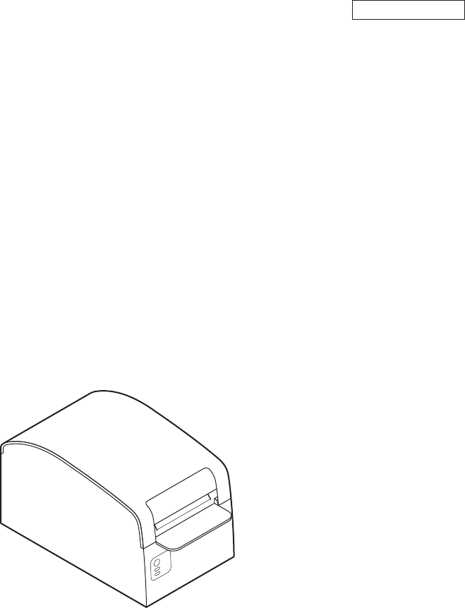
2. EXPLANATION OF PRINTER PARTS 2.1 Printer Appearance Printer cover Cover open lever Operation panel (Front view) Rear connector (Rear view) ● Printer cover Paper is loaded under this cover. ● Cover open lever To refill or replace paper, open the printer cover by lifting the cover open lever.
Operation Panel FEED button POWER LED ERROR LED ● POWER LED Illuminated when the printer power is on and off when the printer power is off. May blink or light in a special mode or in case of failure. ● ERROR LED Illuminated or blinks when paper is empty or in case of failure. The interval length of blinking represents the type of error. ● FEED button Pressing this button once causes the paper to feed one line. The longer the button is pressed, the more paper is fed.
2.2 Printer Cover Inside ● Paper feed roller Feeds paper as part of print mechanism. Print (thermal) head ● Paper-near-end sensor Detects near paper end, change position in accordance with the outer diameter of paper core. Paper feed roller Auto cutter ● Auto cutter Cuts the paper with a command at the end of printing. Cutting method is selectable between partial cut and full cut with a command. ● Print (thermal) head Prints characters and/or graphic data on thermal paper.
3. PREPARATION 3.1 Connecting Interface Cables Confirm that the power switch of the POS terminal is OFF and connect the interface cable. Orient the interface cable connector correctly and insert it into the POS terminal. CAUTION! ■ When disconnecting the cable, always hold the connector. ■ Avoid locating the interface cable in places which may cause tripping or falling.
3.2 Connecting the Cash Drawer 1. Confirm that the power switch of the POS terminal is OFF. 2. Confirm the top and bottom of the cash drawer cable connector and insert it into the cash drawer kick-out connector at the back of the printer. Cash drawer kick-out connector Cash drawer cable connector CAUTION! DO NOT connect any other device than the specified cash drawer to the cash drawer kick-out connector. (DO NOT connect a telephone line either.) (1) Connector Pin Configuration No.
3.3 Partition for Paper Roll At the time of shipment, this partition is set to 80-mm wide (with one partition) or 58-mm wide (with two partitions) depending on the model. Do not remove the partition.
3.4 Adjusting the Paper Near-end Sensor At the time of shipment, the sensor is set to “1”. 1. Lightly push in the paper near-end sensor unit. 2. Move the paper near-end sensor unit to the right and left while keeping to press it. The sensor position is as shown below depending on the diameter of the roll paper used.
4. MAINTENANCE AND TROUBLESHOOTING 4.1 Setting/Replacing the paper roll 1. Lift the cover open lever. 2. Open the printer cover. 3. Insert a paper roll with its print area facing down as shown in the figure and pull out the paper end straightforward by several cm out of the printer. 4. Firmly close the printer cover until a click can be heard. With the factory setting, the paper is fed and cut automatically. See 5.3 Manual Setting of Memory Switch CAUTION! ■ Always use the specified types of paper roll.
4.3 Cleaning the Print Head 1. Turn the POS terminal power off. 2. Open the printer cover. 3. Wait several minutes. Wipe off any debris on the heating element of the head using a cotton swab soaked in ethyl alcohol. Print (thermal) head CAUTION! The print head is hot immediately after printing. DO NOT touch it with your hand. DO NOT touch the heating element of the head with a bare hand or metal object either. 4.4 Self-printing Insert paper into the printer.
4.5 Hexadecimal Dump Printing This function is to print all received data in hexadecimal numbers. If problems such as missing data, data duplication, etc. should occur, this function allows checking whether or not the printer is receiving data correctly. Set paper to the printer and keep the printer cover open. With the FEED button pressed and held, turn the printer power on and then close the printer cover.
Lighting and blinking status of each error including the above is shown below. Status Paper-end POWER LED Lights Lights Paper near-end Lights Lights Cover open Lights Lights Cover open error *1 Lights Cutter lock error Lights Head overheat error Lights Motor overheat error Lights Memory check error ERROR LED Buzzer Lights Low voltage error Lights High voltage error Lights Macro execution wait *2 Lights *1: When the printer is printing.
5.2 Printing Paper Use the print paper shown in the following table or the paper with equivalent quality. Paper Type Product Name Recommended thermal PD160R, PD190R from Ohji Paper paper roll HP220AB-1, PB670, PB770 from Mitsubishi Paper (Unit: mm) +0 d D 4 φ102 or less 4 Maximum print area 72 75 Printing surface Paper width 80 −1 +0 Paper width 58 −1 5 Maximum print area 48 5 Core inner diameter d (mm) φ12 φ25.
5.3 Manual Setting of Memory Switch Memory switches can be set manually or by a command. For manual setting, refer to the next page. The function of each memory switch is shown in the following table. (The white-on-black characters are factory setting.) Switch No.
Switch No.
2. Selecting memory switch When the FEED button is pressed short (within 2 seconds), printing occurs in the order of “Memory SW1” → “Memory SW2” → “Memory SW3” → ......“Memory SW10” → “Save To Memory” → “Memory SW1” → ...... repeatedly. When the memory switch you want to change is reached, press and hold the FEED button (for more than 2 seconds). 3. Selecting each switch item 3-8 items are provided for setting in each switch.
TA74906-00F 1.