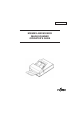
C150-E022-05EN M3093EX AND M3093GX IMAGE SCANNER OPERATOR’S GUIDE
REVISION RECORD Edition Date published Revised contents 01 Dec., 1994 First edition 02 Jan., 1995 Document specification and others changed 03 Apr., 1995 Pick Roller replacement procedure added 04 Septermber, 1995 05 January, 1996 Pad replacement procedure added Appendix C, Declaration of Conformity added Specification No.
Conventions Special information, such as warnings, cautions are indicated as follows: WARNING A WARNING indicates that personal injury may result if you do not follow a procedure correctly. CAUTION A CAUTION indicates that damage to the scanner may result if you do not follow a procedure correctly. NOTICE A NOTICE provides "how-to" tips or suggestions to help you perform a procedure correctly. NOTEs are particularly useful for first-time users.
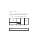
CONTENTS page CHAPTER 1 PREFACE .................................................................................................... 1-1 CHAPTER 2 COMPONENTS ........................................................................................... 2-1 2.1 Checking the Components ......................................................................................... 2-1 2.2 Part Names and Functions ........................................................................................... 2-2 2.
.4 5.3.1 Cleaning the document cover, document holding pad, and document bed ........ 5-2 5.3.2 Cleaning the ADF ............................................................................................... 5-3 Consumables/Periodical replacement parts................................................................. 5-4 5.4.1 Parts number and replacement cycle................................................................... 5-4 5.4.2 Replacing pad ASY ............................................
FIGURES page 2.1 Received components ................................................................................................. 2-1 2.2 M3093EX/GX parts names ......................................................................................... 2-2 2.3 M3093EX/GX Indicators ............................................................................................ 2-4 3.1 SCSI-ID setting .....................................................................................................
TABLES page 1.1 The differences between the M3093EX and the M3093GX ....................................... 1-1 3.1 SCSI-ID setting ........................................................................................................... 3-6 6.1 Check items ................................................................................................................. 6-1 A.1 Installation specifications ............................................................................................
CHAPTER 1 PREFACE This manual describes how to operate the M3093EX and M3093GX image scanners. An image scanner optically reads image information from a document and outputs the information to the host system. The differences between the M3093EX and the M3093GX image scanners are listed in table 1.1. Table 1.
This page is intentionally left blank.
CHAPTER 2 COMPONENTS 2.1 2.2 2.3 Checking the Components Part Names and Functions Indicator Panel Functions After unpacking image scanner, confirm that all the components have been received. This section describes the components of the image scanner and their functions. 2.1 Checking the Components These high precision components must be handled with care. Confirm that all the components shown in figure 2.1 have been received. If any component is missing, please contact your local Fujitsu sales person.
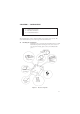
2.2 Part Names and Functions This section shows the exterior view of image scanner. This section also provides names of each part and describes their functions. 2.2.1 Exterior view of image scanner The image scanner can read a document of A4 or letter size at maximum. Document holding pad Document cover Document bed Automatic document feeder (ADF) Indicators Stacker ADF lever ADF paper chute Third party slot opening (M3093EX) Power switch Interface connectors Power inlet Figure 2.
2.2.2 Functions of each part Document cover: Closed over and holds a document to be read. Document bed: A document to be read is placed on the bed also called Flatbed (FB). Document holding pad: Presses a document to the document bed. Automatic document feeder (ADF): Automatically feeds documents to the reading position. Stacker: Stacks the read documents. Power switch: Turns the power on or off. Indicators: These LEDs indicate the status of the scanner.
2.3 Indicator Functions Power Read Check Figure 2.3 M3093EX/GX Indicators 2.3.1 Indicators The meaning of each indicator is as follows: Power indicator (Green): Lights to indicate the power is on. Read (reading in progress) indicator (Green): Lights to indicate reading is in progress. Check (device check) indicator (Yellow): Lights if a device error occurs which may result in a service call. This indicator blinks if a document is jammed in the automatic document feeder.
CHAPTER 3 3.1 3.2 3.3 3.4 3.5 INSTALLATION AND CONNECTIONS Precautions Removing the Carrier Fixing Bracket Connections Mounting the Stacker SCSI-ID Setting This chapter explains how to install and connect the image scanner. 3.1 Precautions Do not install the image scanner in the following places and environments. See the appendix A.1 “Installation Specifications” for the information such as size of installation space. Place the scanner away from electrical noise sources and strong magnetic fields.
3.2 Removing the Carrier Fixing Bracket To keep the scanner from being damaged during shipping, the carrier unit is fixed with a bracket. After placing the carrier unit at the installation place, remove this bracket as explained below. 1 Place the image scanner on the edge of the desk top so that the left side (where ADF is placed) of the scanner extends from the desk top. Do not set the image scanner upside down or on its side. × 2 × Remove the carrier fixing bracket from position A .
3.3 Connections Connect the image scanner using the following procedure. 1 Set the power switch to off. Power switch 2 Connect the power cable. Connect the power cable to the power inlet on the back of the image scanner. Connect the other end of the power cable to a power outlet. Power outlet for North America Power inlet Power cable for Europe 3 Connect the interface cables (for M3093EX).
(M3093GX) Connect the interface cables to the interface connectors and fasten the cables with the catches. Connect the other ends of the cables to the host system. If the image scanner is at the terminal side, connect the terminator. Back of the image scanner Catches Catches Interface cables 3–4 To the host system Terminator If the image scanner is at the terminal side, connect the terminator to the connector to which an interface cable is not connected.
3.4 Mounting the Stacker Mount the stacker using the following procedure. Hook the pins on the stacker to the holes of the image scanner.
3.5 SCSI-ID Setting Use the address switches to set the device address. After the setting turn the power on. Address switch Interface connector Interface cable Figure 3.1 SCSI-ID setting Table 3.1 SCSI-ID setting ID Contents 0 to 7 Available 8, 9 No Operation * When the scanner is terminated device, the termination connector must be connected on one side of the connectors.
CHAPTER 4 OPERATIONS 4.1 Turning on the Power 4.2 Reading a Document in Flatbed Mode 4.3 Reading Documents in ADF Mode Documents can be read in the flatbed mode or automatic document feeder (ADF) mode. In the flat-bed mode, each document is placed on the document bed and is read one by one. In ADF mode, documents are fed and read automatically. This section explains how to turn on the power and how to read documents.
4.2 Reading a Document in Flatbed Mode This section explains how to read a document placed on the document bed. 4.2.1 4–2 Reading a standard-size document If the size of the document is smaller than the document bed, read the document using the following procedure: 1 Open the document cover. 2 Place the document face down on the document board. Correct any curled or folded parts of the document.
Document cover Reference mark 1 4 2 5 Document Document bed Figure 4.1 3 4.2.2 Flatbed reading 2 Reading a page from a thick book To read a page from a thick book, remember the following points: 1 Do not close the document cover forcibly. Keep the cover open for reading. 2 Any document parts that are not in contact with the glass will not be read correctly. 3 Do not move the document during the read operation.
4.2.3 Reading a document larger than the document board If the size of the document is larger than the document board, read the document using the following procedure: 1 Open the document cover at an angle of about 80°, then slide the cover to the direction of the arrow to remove it. 2 Place the document face down on the document bed. 3 Place the document cover over the document. 4 Read the document. 5 After the read operation, remove the document, replace the document cover.
4.3 Reading Documents in ADF Mode This section explains how to read documents using the automatic document feeder. If the following steps are not closely followed, a feed error may occur. 1 Check the documents as follows: (a) Paper quality • Wood-free paper. • PPC paper; Specified by XEROX Corporation. (b) Paper weight • 13.91bs to 27.81bs (c) Paper size • Letter, Legal, A4, A5, B5 (d) Items to avoid • The following documents may be hard to read by ADF.
NOTICE: Paper should be straightened to fit the condition below. More than 30 mm Feed direction Less than 5 mm Less than 5 mm More than 30 mm Feed direction Read surface Top of the paper 2 Read surface Top of the paper Switch the paper select lever. Switch the lever in the following procedures: • Open the automatic document feeder (ADF) while lifting up the ADF lever. • Set the paper select lever. Plain paper: "NORMAL" Heavy paper: "THICK" • Reset the ADF.
3 Pull up the ADF paper chute as follows: • Hold the document cover with one hand and pull up the ADF paper chute with the other hand until it clicks. ADF paper chute Document cover ADF paper chute Push for storage Shaft Figure 4.3 4 Document cover ADF paper chute setting Fan the documents as follows: • Take a 15 to 20 mm thickness of documents. Lightly hold both ends with both hands. Bend the documents into an arch as shown below.
5 Take documents to be placed in the ADF paper chute. The thickness of the documents to be placed in the ADF paper chute is limited depending on the size of the documents as follows: A4 or letter size or smaller: 4 mm or less 6 Angling the documents Angle the document edges as follows: • Place the documents face down with the top to the left as shown in A. The long side is the top for landscape mode and the short side is the top for portrait mode.
7 Open the right and left guides of the ADF paper chute about 5 mm wider than the document width. 8 Place the documents face down onto the ADF paper chute with the top edges facing the automatic feeder hole. 9 Adjust the guides to the document sides. Skewing may occur if there is a gap between the guides and documents. 10 Slide the documents down until they touch the far end of the automatic feeder opening. If the documents hit the far end hard, two or more pages may be fed at once.
This page is intentionally left blank.
CHAPTER 5 MAINTENANCE 5.1 Removing Jammed Documents 5.2 Notes on Daily Use 5.3 Cleaning 5.4 Consumables/Periodical replacement parts This section explains how to remove jammed documents, and provides notes on daily use and cleaning. 5.1 Removing Jammed Documents If documents jam while being fed by the ADF, remove the jammed documents as follows: 1 Remove the documents from the ADF paper chute. 2 Pulling up the ADF lever, open the automatic document feeder. 3 Remove the jammed documents.
5.2 Notes on Daily Use Note the following points on daily use: NOTICE • Do not look directly at the light source during the read operation. Keep the document cover in place. NOTICE • See Section 5.3 “Cleaning”, to clean the document cover, document holding pad, document bed, and the automatic document feeder. Especially, clean the automatic document feeder (ADF) periodically. For the cleaning cycle, see Section 5.3.2, "Cleaning the ADF." 5.3 Cleaning This section explains how to clean the image scanner. 5.
5.3.2 Cleaning the ADF Clean the automatic document feeder (ADF) once every 5,000 pages. The cycle depends on the types of documents used (paper quality, a level of toner fusing on paper). 1 Pull the ADF lever up to open the ADF. 2 Use the dry cloth or a cloth with ethyl alcohol to softly remove dirt and dust as follows. Pad: Wipe the pad in a downward direction (indicated by the arrow). Be careful not to hook the pick spring when wiping. Glass: Wipe the glass lightly.
5.4 Consumables / Periodical replacement parts 5.4.1 Parts number and replacement cycle Customer is responsible to change these items periodically. No. Part name Part number Replacement cycle 1 Pad ASY PA02201-0020 Every 100,000 pages or annually(*1) 2 Pick roller PA02212-K001(*2) Every 200,000 pages or annually(*1) *1: These replacement cycle may vary by the paper quality and cleaning result. When PPC paper is used, replacement cycle may be 300,000 sheets or more by good cleaning.
3 Insert the pad assembly into the ADF frame hole (the bigger one), slide the assembly to the direction of the arrow until it clicks. ADF frame Pad assy NOTICE: Pad can be replaced by aligning the holes of the pad with the pins of the Pad holder. Pad holder Pad Pick spring 5.4.3 Replacing pick roller Replace the pickroller as follows. Thumb Screw Guide A a. Pull the cap up to open the ADF unit. b. Remove two thumb screws shown in Figure 5.4. And remove the Guide A. Thumb Screw Figure 5.
c. Pinch the retaining spring and slide it toward the roller. Free bearing A from the bracket by sliding it toward the roller. A dir ection Bearing A Retaining Spring Figure 5.5 Move the Retaining spring d. Slide the pick roller shaft in the direction of arrow B and remove the shaft from bearing B. The roller shaft can then be lifted and removed as shown in Figure 5.6. Arrow B e. Remove the bearing B. f. Mount the new pick roller in reverse order of removal. Bearing B Figure 5.
CHAPTER 6 TROUBLESHOOTING If a problem occurs, use Table 6.1 to resolve the problem. Table 6.1 Check items Problem Possible cause Response No power The power switch was not turned on. Press the power switch. The power cable was not connected correctly. Connect the power cable correctly. —————————— Read operation does not start. Turn off the power once and make an attempt to turn on the power again. If the power is not turned on, contact your Fujitsu service representative.
Table 6.1 Check items (continued) Problem Possible cause Response The check indicator is on. The carrier fixing bracket was not removed. Remove the carrier fixing bracket as explained in Section 3.2, “Removing the Carrier Fixing Bracket.” —————————— “Check” lamp blinks at 4 seconds period. Paper double feed. Miss pick. Paper jam. Turn the power off then on again. If the check indicator turns on again, contact the sales person in charge or a Fujitsu service representative.
APPENDIX A A.1 Installation Specifications Table A.
173 376 A.2 External Dimensions 530 (Unit: mm) Figure A.
APPENDIX B B.1 Test mode for maintenance CAUTION: Please follow the procedure here or the offset data may be changed incorrectly. If the scanner does not react as the procedure below, turn off the scanner and start from the beginning. (1) Activating a test mode Open the ADF cover and set the sensors to the following state before turning on the image scanner.
(2) Activating the continuous operation test Open the ADF and close it again. If no document is loaded on the ADF within five seconds after closing the ADF, the image scanner runs in flatbed mode. If documents are loaded on the ADF within five seconds after closing the ADF, the image scanner continuously feeds the document from ADF. Once the image scanner start reading documents in the flatbed mode, it does not feed documents from ADF even if documents are loaded on the ADF.
APPENDIX C C.1 Option Name Specification Scanner Feature IPC-2 CA01952-0191 M3093EX M3093GX Image processing • Automatic separation • Image emphasis • Outline extraction • Mirror image • Dynamic threshold • Noise suppression • Smoothing CMP-2 CA M3093GX • 4 Mbyte memory • MH/MR/MMR compression Contact your Fujitsu sales agent for more information. C.2 IPC-2/CMP-2 option board installation WARNING: Follow the outlined procedure to avoid danger from electrical components.
(5) Remove the two screws in the following figure. Two screws (6) Remove the four screws from the interface connector and remove the two screws A in the following figure. Screw A Interface connector screw (7) Remove the cover from the interface PCA. Cover (8) Connect the IPC-2 option board connector and tighten the screw.
(9) Where a CMP-2 is installed, remove the screw from the memory board and detach the memory board. Connect the CMP-2 option board connector and tighten the screw. Screw for IPC-2 IPC-2 option board CMP-2 option board or memory PCA (M3093GX) (not shown) Screw for memor board or CMP-2 (M3093GX) (10) Attach the power supply and PCA assembly in the reverse order of removal.
This page is intentionally left blank.
Comments concerning this manual can be directed to one of the following addresses: FUJITSU LIMITED International Operations Marunouchi 1-6-1, Chiyoda-ku, Tokyo 100, JAPAN TEL: (81-3) 3216-3211 FAX: (81-3) 3213-7174 TLX: J22833 Cable: “FUJITSU LIMITED TOKYO” FUJITSU COMPUTER PRODUCTS OF AMERICA, INC. 2904 Orchard Parkway, San Jose. California 95134-2022, U.S.A. TEL: 1-408-432-6333 FAX: 1-408-432-3908 FUJITSU CANADA, INC. 2800 Matheson Blvd. East, Mississauga.
Reader Comment Form We would appreciate your comments and suggestions for improving this publication. Publication No. Rev. Letter Title Current Date How did you use this publication? Is the material presented effectively? Learning Installing Sales Fully Well Well Reference Maintaining Operating Covered illustrated Organized Clean What is your overall rating of this publication? What is your occupation? Very Good Fair Very Poor Good Poor Your other comments may be entered here.