C150-E048-02EN M3097E+ AND M3097G+ IMAGE SCANNER OPERATOR’S GUIDE
REVISION RECORD Edition Date published 01 Jan., 1996 Revised contents First eddition Specification No.: C150-E048-02EN This digital apparatus does not exceed the Class A limit for radio noise emissions from digital apparatus set out in the Radio interference Regulations of the Canadian Department of Communications.
IMPORTANT NOTE TO USERS READ CAREFULLY ALL OF THIS MANUAL BEFORE USING THIS PRODUCT. IF NOT USED CORRECTLY, UNEXPECTED DAMAGES MAY BE CAUSED TO THE USERS OR THE BYSTANDERS. Conventions for Alerts This manual uses the following coventions for alerts to prevent physical or property damages to users or bystanders. ! CAUTION NOTICE IMPORTANT ii CAUTION indicates that either minor or moderate personal injury may occur if the user does not perform the procedure correctly.
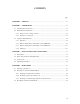
CONTENTS page CHAPTER 1 PREFACE .................................................................................................... 1-1 CHAPTER 2 COMPONENTS ........................................................................................... 2-1 2.1 Checking the Components ........................................................................................... 2-1 2.2 Part Names and Functions ........................................................................................... 2-2 2.
CHAPTER 5 MAINTENANCE ......................................................................................... 5-1 5.1 Removing Jammed Documents ................................................................................... 5-1 5.2 Notes on Daily Use...................................................................................................... 5-2 5.3 Cleaning ....................................................................................................................... 5-2 5.3.
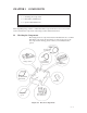
FIGURES page Figure 2.1 Received components ...................................................................................... 2-1 Figure 2.2 M3097E+/G+ parts names ............................................................................... 2-2 Figure 2.3 M3097E+ operator panel ................................................................................. 2-4 Figure 2.4 M3097G+ operator panel ................................................................................. 2-4 Figure 4.
TABLES page Table 1.1 The differences between the M3097E+ and the M3097G+ ............................. 1-1 Table 6.1 Check items ..................................................................................................... 6-1 Table A.1 Installation specifications ................................................................................
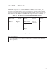
CHAPTER 1 PREFACE This manual describes how to operate the M3097E+ and M3097G+ image scanners. The M3097E+ now supports a document counter function. The M3097G+ similarly supports a new document counter and also features an 8-bit grayscale function. An image scanner optically reads image information from a document and outputs the information to the host system. The differences between the M3097E+ and the M3097G+ image scanners are listed in table 1.1. Table 1.
This page is intentionally left blank.
CHAPTER 2 COMPONENTS 2.1 Checking the Components 2.2 Part Names and Functions 2.3 Operator Panel Functions After unpacking image scanner, confirm that all the components have been received. This section describes the components of the image scanner and their functions. 2.1 Checking the Components These high precision components must be handled with care. Confirm that all the components shown in figure 2.1 have been received. If any component is missing, please contact your local Fujitsu sales person.
2.2 Part Names and Functions This section shows the exterior view of image scanner. This section also provides names of each part and describes their functions. 2.2.1 Exterior view of image scanner The image scanner can read a document of A3 or double-letter size at maximum. Document cover Automatic document feeder (ADF) Document holding pad Document bed Extension Operator panel Stacker ADF paper chute Power switch ADF lever Extension Power inlet Figure 2.
2.2.2 Functions of each part Document cover: Closed over and holds a document to be read. Document bed: A document to be read is placed on the bed also called Flatbed (FB). Document holding pad: Presses a document to the document bed. Automatic document feeder (ADF): Automatically feeds documents to the reading position. Stacker: Stacks the read documents. Extension: Keeps the stacked documents from overhanging. Power switch: Turns the power on or off.
2.3 Operator Panel Functions The operator panel has indicators and a liquid crystal display screen for displaying image scanner status. The operator panel also has operation buttons. Liquid crystal display screen Buttons Mode 1 ADF Size Density Resolution Stop Halftone Start Power Ready Mode 2 Landscape Figure 2.3 M3097E+ operator panel Liquid crystal display screen Document Check Indicators Buttons Mode 1 Power Read Mode 2 Figure 2.
2.3.1 Indicators The meaning of each indicator is as follows: Power indicator (Green): Lights to indicate the power is on. Ready (for reading) indicator (Green) (M3097E+): Lights when the image scanner becomes ready to read a document in the manual mode. This indicator turns off when the start button is pressed to read a document. Read (reading in progress) indicator (Green) (M3097G+): Lights to indicate reading is in progress.
Liquid crystal display screen The screen has two message lines. The current read mode status is displayed in the upper line, and messages and the modes set by the buttons are displayed in the lower line. Upper line ADF A 4 4 0 0 L .
The ADF, size, density, resolution, landscape, half-tone, document, and mode 1 and 2 buttons described below are effective unless otherwise specified by the host system. Automatic document feeder (ADF) button: Selects whether to feed documents automatically by ADF or manually on the flatbed. When this button is pressed, the lower line is displayed as shown in Screen 1.
Density button: Selects a density for the read operation. When this button is pressed, the lower line is displayed as shown in Screen 3. Each time this switch is pressed, the blinking part in the lower line changes, and the density indicated on the upper line changes according to the blinking part. Screen 3 — The upper line shows a typical example. Upper line Lower line ADF LG De n . : 4 0 0 P . > AT ( A u t o ) 1 Blinking The lower line is displayed as shown below.
Landscape button: Specifies whether reading is done in landscape or portrait mode. When this button is pressed, the lower line is displayed as shown in Screen 5. Each time this button is pressed, the blinking part changes in turn, and the mode indicated on the upper line changes accordingly. Screen 5 — The upper line shows a typical example. Upper line Lower line ADF L T S i z e : DL T L T 4 0 0 LG A 3 P . > A 4 Blinking Explanation: Display : Landscape mode.
Document button: Selects the type of document. When this button is pressed, the lower line is displayed as shown in Screen 7. Each time this button is pressed, “LINE” or “PHOTO” starts blinking in turn, and the document selection indication displayed on the upper line changes accordingly. Screen 7 — The upper line shows a typical example. Upper line Lower line ADF LG 3 0 0 HT 1 P . > DOC . : L . ( L i n e ) P . ( P h o t o ) Blinking Explanation: Display (lower line) Explanation P.
2.3.3 Buttons and liquid crystal display screen (M3097G+) Liquid crystal display screen: Displays messages only. The mode buttons have the following functions: Mode 1 button: See Section 5.3.4, 5.4 and 5.5. Mode 2 button: See Section 5.3.4, 5.4 and 5.5. When error messages are displayed on liquid crystal display screen, press this button to enable the read operation. 2.3.4 Messages Error messages (temporary errors) If a temporary error occurs in the scanner, one of the following messages is displayed.
Device errors One of the following messages is displayed if an device errors in the scanner. If one of the following error messages is displayed, turn the power off and then on again. If the same message is displayed again, contact your service representative.
CHAPTER 3 INSTALLATION AND CONNECTIONS 3.1 Precautions 3.2 Removing the Carrier Fixing Bracket 3.3 Connections 3.4 Mounting the Stacker This chapter explains how to install and connect the image scanner. 3.1 Precautions Do not install the image scanner in the following places and environments. See the appendix A.1 “Installation Specifications” for the information such as size of installation space. Place the scanner away from electrical noise sources and strong magnetic fields.
3.2 Removing the Carrier Fixing Bracket To keep the scanner from being damaged during shipping, the carrier unit is fixed with a bracket. After placing the carrier unit at the installation place, remove this bracket as explained below. 1 Place the image scanner on the edge of the desk top so that the left side (where ADF is placed) of the scanner extends from the desk top. Do not set the image scanner upside down or on its side. × 2 × Remove the carrier fixing bracket from position A.
3.3 Connections Connect the image scanner using the following procedure. 1 Set the power switch to off. Power switch 2 Connect the power cable. Connect the power cable to the power inlet on the back of the image scanner. Connect the other end of the power cable to a power outlet. Power outlet for North America Power inlet Power cable for Europe 3 Connect the interface cables (for M3097E+).
(M3097G+) Connect the interface cables to the interface connectors and fasten the cables with the catches. Connect the other ends of the cables to the host system. If the image scanner is at the terminal side, connect the terminator. Back of the image scanner Catches Catches Interface cables NOTICE 3–4 To the host system Terminator If the image scanner is at the terminal side, connect the terminator to the connector to which an interface cable is not connected.
3.4 Mounting the Stacker Mount the stacker and extensions using the following procedure. 1 Mount the stacker. Hook the pins on the stacker to the claws on the image scanner. Stacker Pin Claw 2 Mount the extensions. Mount extensions to the stacker and to the ADF paper chute.
This page is intentionally left blank.
CHAPTER 4 OPERATIONS 4.1 Turning on the Power 4.2 Reading a Document in Flatbed Mode 4.3 Reading Documents in ADF Mode Documents can be read in the flatbed mode or automatic document feeder (ADF) mode. In the flat-bed mode, each document is placed on the document bed and is read one by one. In ADF mode, documents are fed and read automatically. This section explains how to turn on the power and how to read documents. 4.1 Turning on the Power This section explains how to turn on the power.
4.2 Reading a Document in Flatbed Mode This section explains how to read a document placed on the document bed. ! 4.2.1 4–2 CAUTION High luminance: Do not look directly at the light source during read operation. Keep the document cover in place. Reading a standard-size document If the size of the document is smaller than the document bed, read the document using the following procedure: 1 Open the document cover. 2 Place the document face down on the document board.
Document cover Reference mark Document Operator panel Document bed Figure 4.1 Flatbed reading Portrait mode Short side Long side Landscape mode 3 Document bed 3 Document 4.2.2 Reading a page from a thick book To read a page from a thick book, remember the following points: 1 Do not close the document cover forcibly. Keep the cover open for reading. 2 Any document parts that are not in contact with the glass will not be read correctly. 3 Do not move the document during the read operation.
4.2.3 Reading a document larger than the document board If the size of the document is larger than the document board, read the document using the following procedure: 1 To remove the document cover, remove the screw from the document cover. 2 Place the document face down on the document bed. 3 Place the document cover over the document. 4 Read the document. 5 After the read operation, remove the document, replace the document cover.
4.3 Reading Documents in ADF Mode This section explains how to read documents using the automatic document feeder. If the following steps are not closely followed, a feed error may occur. After documents have been read in ADF mode, a squeaking noise is sometimes heard. This is not a problem as the noise is caused by the self-cleaning action of the rollers. 1 Check the documents as follows: (a) Paper quality • Wood-free paper. • PPC paper; Specified by XEROX Corporation. (b) Paper weight • 13.
2 Pull up the ADF paper chute as follows: • Hold the document cover with one hand and pull up the ADF paper chute with the other hand to unlock the ADF paper chute. ADF paper chute Document cover Figure 4.3 3 ADF paper chute setting Fan the documents as follows: • Take a 15 to 20 mm thickness of documents. Lightly hold both ends with both hands. Bend the documents into an arch as shown below. • Then hold the documents tightly with both hands, and straighten the documents.
4 Take documents to be placed in the ADF paper chute. The thickness of the documents to be placed in the ADF paper chute is limited depending on the size of the documents as follows: A4 or letter size or smaller: 8 mm or less Size larger than A4: 4 mm or less 5 Angling the documents Angle the document edges as follows: • Place the documents face down with the top to the left as shown in A. The long side is the top for landscape mode and the short side is the top for portrait mode.
6 Open the right and left guides of the ADF paper chute about 5 mm wider than the document width. 7 Place the documents face down onto the ADF paper chute with the top edges facing the automatic feeder hole. 8 Adjust the guides to the document sides. Skewing may occur if there is a gap between the guides and documents. 9 Slide the documents down until they touch the far end of the automatic feeder opening. If the documents hit the far end hard, two or more pages may be fed at once.
CHAPTER 5 MAINTENANCE 5.1 Removing Jammed Documents 5.2 Notes on Daily Use 5.3 Cleaning 5.4 Replacing the Lamp Unit 5.5 SCSI Address Setting (M3097G+) 5.6 Replacing the Pad 5.7 Document counter display and reset This section explains how to remove jammed documents, and provides notes on daily use and cleaning. If "Please clean-up!!" is displayed on the operator panel during the read operation, clean the mirror as explained in Section 5.3.4.
5.2 Notes on Daily Use Note the following points on daily use: • The image scanner requires one to three minutes to warm up after the power has been turned on. During this time, the message “Warming-up Now!!” is displayed on the screen. • Do not look directly at the light source during the read operation. Keep the document cover in place. • See Section 5.3 “Cleaning”, to clean the document cover, document holding pad, document bed, and the automatic document feeder. IMPORTANT 5.
5.3.2 Cleaning the ADF Clean the ADF once every 5,000 pages. The cycle depends on the types of documents used (page quality, a level of toner fusing on paper). 1 Pull the ADF lever up to open the ADF. 2 Use the dry cloth or a cloth with ethyl alcohol to softly remove dirt and dust as follows. Pad: Wipe the pad in a downward direction (indicated by the arrow). Be careful not to hook the pick spring when wiping. Glass: Wipe the glass lightly. See Section 5.
5.3.3 Cleaning the coupled feed roller 1 Pull the ADF lever up to open the ADF. 2 Pull the ADF lamp replacement lever up while pushing the lever in the direction indicated by the arrow in Figure 5.4. 3 Clean the surface of the coupled feed roller by the cloth with ethyl alcohol. NOTICE 5.3.4 If the coupled feed rollers are excessively pushed in the direction of the arrow above during cleaning, the automatic document feed performance may be affected.
5.4 Replacing the Lamp Unit Hot: Replace the lamp unit in the following procedure. If an optical alarm occurs, and the following message is displayed, replace the lamp unit as follows. Op t i c a l A l a r m • Turn off the power once. Then, turn on the power while pressing the mode 1 button. For M3097G+, press the mode 2 button so that "Lamp Exchange" blinks.
• Pull the ADF lever up and open the ADF. • Pull the ADF lamp replacement lever up while pushing the lever in the direction indicated by the arrow in Figure 5.4. • Hold the lamp unit levers and pull the glass up. Wipe the bottom surface of the glass if it is dirty. Automatic document feeder ADF lamp replacement lever Lamp unit levers ADF lever Glass Figure 5.4 Lamp unit removal 1 Lamp unit levers Lamp unit Figure 5.
• Then carefully pull it up with the front and ( 1 in Figure 5.6) first and the back and ( 2 in Figure 5.6) next. If the levers are pulled up carelessly, the lamp may be broken. ! CAUTION Hot: The lamp surface may be very hot. Be careful not to touch the lamp surface. 2 A Lamp unit Lamp unit levers 1 A Lamp unit insert direction (vertical) Arrows indicating the lamp unit insert position Figure 5.6 Lamp unit replacement • Obtain a new lamp unit. • Hold the new lamp unit with both hands.
Glass Levers Openings Figure 5.7 Inserting the glass • Close the ADF to lock ADF lever.
5.5 SCSI Address Setting (M3097G+) Press the power switch while pressing the mode 1 button. The liquid crystal display unit displays the following screen. SCS I I D L amp E x c h a n g e Blinking Press the mode 2 button to shift the blinking position. To set a device address, press the mode 1 button while “SCSI ID” is blinking. SCS I I D 0 The liquid crystal display screen displays this screen. A value from 0 to 7 is displayed in turn each time the mode 1 button is pressed.
5.6 Replacing the pad (1) Pull up the ADF open and close lever to open the ADF. (2) Remove the four screws shown in Figure 5.8 to remove the two pads. (3) Install the pad by reversing the removal procedure. Figure 5.8 NOTICE 5 – 10 Removing the pad Attach the pad so that the corner cut is top left. Attach the pad so that the edges do not go under the pick spring 2 or over guide C.
5.7 Document counter display and reset The Document counter is useful for users to check the total number of scanned documents before regular cleaning. This counter can be displayed or reset using the following procedures. (1) Turn on the power while holding down the Mode 1 button. The scanner displays the following message. For M3097E+ : Please wait Lamp is cooling off For M3097G+ : SCSI ID Lamp Exchange Continue pressing the Mode 1 button until the scanner displays the screen A.
This page is intentionally left blank.
CHAPTER 6 TROUBLESHOOTING If a problem occurs, use Table 6.1 to resolve the problem. Table 6.1 Check items Problem Possible cause Response No power The power switch was not turned on. Press the power switch. The power cable was not connected correctly. Connect the power cable correctly. —————————— Turn off the power once and make an attempt to turn on the power again. If the power is not turned on, contact your Fujitsu service representative.
Table 6.1 Check items (continued) Problem Possible cause Response The lamp does not light (ready) while the power indicator blinks. The interface cables were not connected correctly. Connect the interface cables correctly. The terminator was not connected. Connect the terminator. The check indicator is on. The carrier fixing bracket was not removed. Remove the carrier fixing bracket as explained in Section 3.2, “Removing the Carrier Fixing Bracket.” —————————— Turn the power off then on again.
APPENDIX A.1 Installation Specifications Table A.
External Dimensions 173 497 A.2 696 (Unit: mm) Figure A.
Comments concerning this manual can be directed to one of the following addresses: FUJITSU LIMITED International Operations Marunouchi 1-6-1, Chiyoda-ku, Tokyo 100 JAPAN TEL: (81-3) 3216-3211 FAX: (81-3) 3213-7174 TLX: J22833 Cable: “FUJITSU LIMITED TOKYO” FUJITSU NORDIC AB Kung Hans Vag, S-191 76 Sollentuna, SWEDEN TEL: 46-8-626-6000 FAX: 46-8-626-6711 FUJITSU ITALIA S.p.A. Via Melchiorre Gioia, No.8-20124 Milano, ITALY TEL: 39-2-63651 FAX: 39-2-6572257 FUJITSU COMPUTER PRODUCTS OF AMERICA, INC.
FUJITSU LIMITED Reader Comment Form We would appreciate your comments and suggestions for improving this publication. Publication No. Rev. Letter Title How did yu use this publication? Learning Reference Installing Maintaining Is the material presented effectively? Fiar Poor Fully Covered Sales Operating What is your overall rating of this publication? Very Good Good Current Date Well Illustrated Well Organized What is your occupation? Very Poor Your other comments may be entered here.