MAA3182 SERIES MAB3091, MAB3045 SERIES MAC3091, MAC3045 SERIES DISK DRIVES PRODUCT MANUAL C141-E035-03EN
REVISION RECORD Edition Date published Revised contents 01 Mar., 1997 02 Nov., 1997 Pages 1-2, 1-5 to 1-11, 2-2 to 2-5, 2-7, 3-2 to 3-4, 3-7 to 3-10, Chapter 4, 5-2, 5-3, 5-5 to 5-10, 5-12 to 5-24, Chapter 6, Appendix A, C-1, C-2, D-2, Appendix E revised. 03 Jan., 1998 Pages 1-3, 1-4, 1-7 to 1-9, Chapter 2, 3-2 to 3-4, 3-6, 3-10, 4-4, 4-5, 4-7, 4-8, 4-10, 4-11, 4-14, 4-22, 4-23, 4-27, 6-2, 6-3, D-2 revised. Specification No.
FOR SAFE OPERATION Handling of This manual This manual contains important information for using this product. Read thoroughly before using the product. Use this product only after thoroughly reading and understanding especially the section “Important Alert Items” in this manual. Keep this manual handy, and keep it carefully. FUJITSU makes every effort to prevent users and bystanders from being injured or from suffering damange to their property. Use the product according to this manual.
Related Standards Specifications and functions of products covered by this manual comply with the following standards. Standard (Text) No. Name ANSI X3.131-1986 American National Standard for American National Information Systems—Small Computer Standards Institute System Interface (SCSI) (ANSI) ANSI X3.131-1994 American National Standard for American National Information Systems—Small Computer Standards Institute System Interface - 2(SCSI-2) (ANSI) X3T9.2/85-52 Rev 4.
PREFACE This manual describes the MAA3182xx (hereafter, MAA31xxxx), MAB3091xx, MAB3045xx (hereafter, MAB30xxxx), MAC3091xx, MAC3045xx (hereafter, MAC30xxxx) series 3.5-inch fixed disk drives with an embedded SCSI controller. This manual details the specifications and functions of the above disk drive, and gives the requirements and procedures for installing it into a host computer system. This manual is written for users who have a basic understanding of fixed disk drives and their use in computer systems.
CONVENTIONS This manual uses the following conventions for alerts to prevent physical or property damages to users or by standards. DANGER DANGER indicates that personal injury will occur if the user does not perform the procedure correctly. WARNING WARNING indicates that personal injury could occur if the user does not perform the procedure correctly. CAUTION CAUTION indicates that either minor or moderate personal injury may occur if the user does not perform the procedure correctly.
DISCLAIMER Failure of the MAA31xxxx, MAB30xxxx and MAC30xxxx series intelligent disk drive is defined as a failure requiring adjustments, repairs, or replacement. Fujitsu is not responsible for drive failures caused by misuse by the user, poor environmental conditions, power trouble, host problems, cable failures, or any failure not caused by the drive itself.
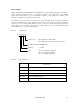
MANUAL ORGANIZATION PRODUCT MANUAL (This manual) viii 1. 2. 3. 4. 5. 6. General Description Specifications Data Format Installation Requirements Installation Diagnostics and Maintenance SCSI Physical Interface Specifications 1. SCSI Bus 2. SCSI Message 3. SCSI Bus Error Recovery Processing SCSI Logical Interface Specifications 1. 2. 3. 4. 5. Command Processing Data Buffer Management Command Specification Sense Data and error Recovery Procedure Disk Medium Management Maintenance Manual 1. 2. 3. 4.
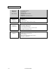
CONTENTS CHAPTER 1 page GENERAL DESCRIPTION .......................................................................... 1-1 1.1 Standard Features ........................................................................................................... 1-2 1.2 Hardware Structure......................................................................................................... 1-5 1.3 System Configuration...........................................................................................
4.3 Connection Requirements .............................................................................................. 4-14 4.3.1 Single-ended 16-bit SCSI model (MAA31xxSP, MAB30xxSP, MAC30xxSP) ............ 4-14 4.3.2 SCA2 type SCSI model (MAA31xxSC, MAB30xxSC, MAC30xxSC)......................... 4-22 4.3.3 Cable connector requirements ........................................................................................ 4-24 4.3.4 External operator panel.....................................
A.1 Locations of Connectors and Setting Terminals (MAx3xxxSC: SCA2 type 16-bit SCSI)......................................................................... A-2 A.2 Locations of Connectors and Setting Terminals (MAx3xxxSP: single-ended type 16-bit SCSI)............................................................... A-3 APPENDIX B SETTING TERMINALS................................................................................ B-1 B.1 Setting Terminals (MAx3xxxSP: Single-ended 16-bit SCSI).............
FIGURES 1.1 page MAA31xxSC outer view................................................................................................ 1-5 1.2 MAA31xxSP outer view ................................................................................................ 1-6 1.3 MAB30xxSC outer view ................................................................................................ 1-6 1.4 MAB30xxSP outer view..........................................................................................
4.17 16-bit SCSI interface connector...................................................................................... 4-15 4.18 Power supply connector (16-bit SCSI model) ................................................................ 4-15 4.19 External operator panel connector (CN1) ....................................................................... 4-16 4.20 External operator panel connector (CN7) ....................................................................... 4-17 4.
TABLES 2.1 page Function specifications................................................................................................... 2-2 2.2 Environmental/power requirements................................................................................ 2-4 2.3 SCSI function specifications........................................................................................... 2-7 3.1 Zone layout and track capacity (MAA31xxxx) ..............................................................
CHAPTER 1 GENERAL DESCRIPTION 1.1 Standard Features 1.2 Hardware Structure 1.3 System Configuration This chapter describes the feature and configuration of the intelligent disk drives (IDD). IDDs are high performance large capacity 3.5-inch fixed disk drives with an embedded SCSI controller. The interface between the IDD and host system is based on SCSI (Small Computer System Interface) standard [ANSI X3.131 - 1986: Small Computer System Interface (SCSI), ANSI X3.
1.1 Standard Features (1) Compactness Since the SCSI controller circuit is embedded in the standard 3.5-inch fixed disk drive form factor, the IDD is extremely compact. The IDD can be connected directly to the SCSI bus of the host system .
Note: The maximum data transfer rate in asynchronous mode may be limited by the response time of initiator and the length of SCSI bus length. The maximum data transfer rate in synchronous mode on the single-ended SCSI bus may be limited by the cable length, transmission characteristics of the SCSI bus and the connected SCSI device number. (5) Continuous block processing The addressing method of data blocks is logical block address.
(10) Error recovery The IDD can try to recover from errors in SCSI bus or the disk drive using its powerful retry processing. If a recoverable data check occurs, error-free data can be transferred to the initiator after being corrected in the data buffer. The initiator software is released from the complicated error recover processing by these error recovery functions of the IDD.
(18) Low power consumption By using highly integrated LSI components, the power consumption of the IDD is very low, and this enables the unit to be used in wide range of environmental conditions. (19) Low noise and low vibration Approx. 4.2 bels for the IDD. This makes it ideal for office use. The IDD has rubber vibration isolators, which minimize the transfer of vibration. (20) Microcode downloading The IDD implements the microcode download feature. maintainability of the IDD and function enhancing.
1-6 Figure 1.2 MAA31xxSP outer view Figure 1.
Figure 1.4 MAB30xxSP outer view Figure 1.5 MAC30xxSC outer view Figure 1.
(1) Disks The disks have an outer diameter of 95 mm (3.74 inch) and inner diameter of 25 mm (0.98 inch). The disks are good for at least 10,000 contact starts and stops. Each model contains following number of disks. MAA3182:10 MAB3091, MAC3091:5 MAB3045, MAC3045:3 (2) Heads The MR (Magnet - Resistive) of the CSS (contact start/stop) type heads are in contact with the disks when the disks are not rotating, and automatically float when the rotation is started. Figure 1.
(4) Actuator The actuator, which uses a rotary voice coil motor (VCM), consumes little power and generates little heat. The head assembly at the end of the actuator arm is controlled and positioned via feedback of servo information in the data. The actuator positions heads on the CCS zone over the disk and is locked by the mechanical lock when the power is off or the spindle motor is stopped.
1.3 System Configuration Figure 1.8 shows the system configuration. The IDDs are connected to the SCSI bus of host systems and are always operated as target. The IDDs perform input/output operation as specified by SCSI devices which operate as initiator. Figure 1.
(2) Addressing of peripheral device Each SCSI device on the bus has its own unique address (SCSI ID:#n in Figure 1.6). For input/output operation, a peripheral device attached to the SCSI bus that operates as target is addressed in unit called as logical unit. A unique address (LUN: logical unit number) is assigned for each logical unit. The initiator selects one SCSI device by specifying that SCSI ID, then specifies the LUN to select the peripheral device for input/output operation.
CHAPTER 2 SPECIFICATIONS 2.1 Hardware Specifications 2.2 SCSI Function Specifications This chapter describes specifications of the IDD and the functional specifications of the SCSI. 2.1 Hardware Specifications 2.1.1 Model name and part number Each model has a different data format and front panel type when shipped. (See Appendix D for the model name (type) and product number.) The data format can be changed by reinitializing with the user's system.
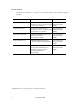
2.1.2 Function specifications Table 2.1 shows the function specifications of the IDD. Table 2.1 Function specifications Specification MAB3045xx 4.55 GB 5.
(*1) The formatted capacity can be changed by changing the logical block length and using spare sector space. See Chapter 3 for the further information. (*2) The number of user cylinders indicates the max., and includes the alternate cylinder. The number of user cylinders and alternate cylinders can be specified at format of the IDD.
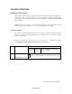
2.1.3 Environmental specifications Table 2.2 lists environmental and power requirements. Table 2.2 Environmental/power requirements MAA3182xx MAB3091xx MAB3045xx Operating Temperature (*1) Non-operating – 40 to 60°C DE surface temperature at operating 5 to 55°C Gradient 15°C/h or less Operating 20 to 80%RH Non operating 20 to 80%RH Packaged (inside of a week) 5 to 90%RH Maximum wet bulb temperature 29°C (no condensation) Operating (*3) 0.3 mm (5 to 20Hz)/0.
(*6) The terminator power pin (SCSI connector) which supplies power to other terminators is not used (See Section 4.3). (*7) High frequency noise is less than 100 mVp-p. 2.1.4 Error rate Errors detected during initialization and replaced by alternate block assignments are not included in the error rate. Data blocks to be accessed should be distributed over the disk medium equally.
(3) Service life The service life under suitable conditions and treatment is as follows. The service life is depending on the environment temperature. Therefore, the user must design the system cabinet so that the average DE surface temperature is as possible as low.
2.2 SCSI Function Specifications Table 2.3 shows the SCSI functions provided with the IDD. See Appendix E for the SCSI interface functions provided for the IDD. Refer to the OEM Manual –SCSI Physical Specifications–, for details or specifications. Table 2.
CHAPTER 3 DATA FORMAT 3.1 Data Space 3.2 Logical Data Block Addressing 3.3 Defect Management This chapter explains data space definition, logical data block addressing, and defect management on the IDD. 3.1 Data Space The IDD manages the entire data storage area divided into the following three data spaces.
Figure 3.1 Cylinder configuration Apart from the above logical configuration, the IDD intends to increase the storage capacity by dividing all cylinders into several zones and changing a recording density of each zone. Tables 3.1 and 3.2 show the zone layout and the track capacity.
Table 3.
(1) User space The user space is a storage area for user data. The data format on the user space (the length of data block and the number of data blocks) can be specified with the MODE SELECT or MODE SELECT EXTENDED command. The default number of cylinders in the user space is 9,041 for MAA31xxxx, 8,491 for MAB30xxxx and 8,691 for MAC30xxxx.
3.1.2 Alternate spare area The alternate spare area is provided in the last track of each primary cylinder in the user space, and in the last track of the cylinder and the alternate cylinder. The spare area in each cylinder is placed at the end of the last track as shown in Figure 3.2. These spare sectors are located in the end of the track logically, not necessarily located at the end physically because of track skew or cylinder skew. (Details are explained on Subsection 3.1.3.
3.1.3 Track format (1) Physical sector allocation Figure 3.4 shows the allocation of the physical sectors in a track. The length in bytes of each physical sector and the number of sectors per track vary depending on the logical data block length. The unused area (G4) exists at the end of the track in formats with most logical data block lengths. The interval of the sector pulse (length of the physical sector) is decided by multiple of 15MHz free running frequency.
(2) Track skew and cylinder skew To avoid waiting for one turn involved in head and cylinder switching, the first logical data block in each track is shifted by the number of sectors (track skew and cylinder skew) corresponding to the switching time. Figure 3.5 shows how the data block is allocated in each track.
3.1.4 Sector format Each sector on the track consists of an ID field, a data field, and a gap field which separates them. Figure 3.6 gives sector format examples. Figure 3.6 Sector format Each sector on the track consists of the following fields: (1) Gaps (G1) The gap length at the time of formatting (initializing) is listed in Figure 3.6. Pattern X'00' is written on the gap field. (2) PLO Sync In this field, pattern X'00' in the length in bytes listed in Figure 3.6 is written.
(6) BCRC It is a 2-byte error detection code. Errors in the ID field. Single burst errors with lengths of up to 16 bits for each logical block can be detected. (7) ECC 24-byte data error detection/correction code for the data field. It is possible to on-the-fly correct the single burst errors with lengths of up to 89 bits. (8) PAD 1 A specified length of x‘00’ pattern shown in Figure 3.6 is written in this field. This field includes the variation by rotation and circuit delay till reading/writing.
3.1.5 Format capacity The size of the usable area for storing user data on the IDD (format capacity) varies according to the logical data block or the size of the spare sector area. Table 3.4 lists examples of the format capacity when the typical logical data block length and the default spare area are used. The following is the general formula to calculate the format capacity.
3.2 Logical Data Block Addressing Independently of the physical structure of the disk drive, the IDD adopts the logical data block addressing as a data access method on the disk medium. The IDD relates a logical data block address to each physical sector at formatting. Data on the disk medium is accessed in logical data block units. The INIT specifies the data to be accessed using the logical data block address of that data.
3.3 Defect Management 3.3.1 Defect list Information of the defect location on the disk is managed by the defect list. The following are defect lists which the IDD manages. • P list (Primary defect list): This list consists of defect location information available at the disk drive shipment and is recorded in a system space. The defects in this list are permanent, so the INIT must execute the alternate block allocation using this list when initializing the disk.
• Alternate sector treatment: The logical data block corresponding to defective sectors is allocated to unused spare sectors in the same cylinder or unused spare sectors in the alternate cylinder. The alternate block allocation is executed by the FORMAT UNIT command, the REASSIGN BLOCKS command, or the automatic alternate block allocation. Refer to OEM Manual–SCSI Logical Specifications–for details of specifications on these commands.
: n represents a logical data block number : Defective sector : Unused spare sector Figure 3.7 Alternate block allocation by FORMAT UNIT command If the data block verifying operation (certification) is not permitted (DCRT flag = 0) in the FORMAT UNIT command, the IDD checks all initialized logical data blocks by reading them out after the above alternate block allocation is made to initialize (format) the disk.
(2) Alternate block allocation by REASSIGN BLOCKS command When the REASSIGN BLOCKS command is specified, the alternate block is allocated to the defective logical data block specified by the initiator by means of alternate sector treatment. If there are unused spare sectors in the same cylinder as the specified defective logical data block, the alternate block is allocated to these unused spare sectors.
(3) Automatic alternate block allocation If the ARRE flag in the MODE SELECT parameter permits the automatic alternate block allocation, the IDD automatically executes the alternate block allocation and data duplication on the defective data block detected during the READ EXTENDED command. This allocation method is the same as with the REASSIGN BLOCKS command (alternate sector treatment). IMPORTANT Automatic alternate block allocation is made only once during the execution of one command.
CHAPTER 4 INSTALLATION REQUIREMENTS 4.1 Mounting Requirements 4.2 Power Supply Requirements 4.3 Connection Requirements This chapter describes the environmental, mounting, power supply, and connection requirements. 4.1 Mounting Requirements 4.1.1 External dimensions Figures 4.1 to 4.4 show the external dimensions of the IDD and the positions of the holes for the IDD mounting screws. Note: Dimensions are in mm.
Figure 4.
Figure 4.
Figure 4.
Figure 4.
4.1.2 Mounting The permissible orientations of the IDD are shown in Figure 4.5, and the tolerance of the angle is ±5° from the horizontal plane. (a) Horizontal –1 (b) Horizontal –2 (c) Vertical –1 Direction of gravity (d) Vertical –2 (e) Upright mounting –1 Figure 4.5 4.1.
c) Tightening torque of screw must be secured with 6kg-cm. Damage : To absolutely guarantee integrity of the IDD disk enclosure (DE) insulation once actually mounted to the frame inside the system, special attention must be given to the cautionary notes below. Figure 4.6 (2) Mounting frame structure Limitation of side-mounting Mount the side using the screw holes at both the ends as shown in Figure 4.7. Do not use the center hole. Do not use these holes Use these holes Figure 4.
(3) Environmental temperature Temperature condition at installed in a cabinet is indicated with ambient temperature measured 3 cm from the disk drive. At designing the system cabinet, consider following points. • Make a suitable air flow so that the DE surface temperature does not exceed 55°C. CAUTION An air flow with an adequate wind velocity must be maintained to deal with much heat generated from the MAC30xxxx. Reference value: An air flow with a wind velocity of more than 0.
(4) Service clearance area The service clearance area, or the sides which must allow access to the IDD for installation or maintenance, is shown in Figures 4.9. [Surface P’] • Setting terminal • External operator panel connector • Spindle sync connector [Surface R] • Hole for mounting screw [Surface P] • Cable connection [Surface Q] • Hole for mounting screw Figure 4.
MAA31xxxx Air pressure adjustment hole MAB30xxxx Air pressure adjustment hole MAC30xxxx Air pressure adjustment hole Figure 4.
4.2 Power Supply Requirements (1) Allowable input voltage and current The power supply input voltage measured at the power supply connector pin of the IDD (receiving end) must satisfy the requirement given in Subsection 2.1.3. (For other requirements, see Items (4) and (5) below.) (2) Current waveform (reference) Figure 4.11 shows the waveform of +12 VDC. MAA31xxxx, MAC30xxxx current wave form MAB30xxxx current wave form Figure 4.
c) In a system which does not use the terminating resistor power supply signal (TERMPWR) on the SCSI bus, the requirements for +5 VDC given in Figure 4.13 must be satisfied between the IDD and the SCSI device with the terminating resistor circuit. SCSI devices with the terminating resistor Figure 4.
(4) Sequential starting of spindle motors After power is turned on to the IDD, a large amount of current flows in the +12 VDC line when the spindle motor rotation starts. Therefore, if more than one IDD is used, the spindle motors should be started sequentially using one of the following procedures to prevent overload of the power supply unit. For how to set a spindle motor start control mode, see Subsection 5.3.2. a) Issue START/STOP commands at 20-second intervals to start the spindle motors.
4.3 Connection Requirements 4.3.1 Single-ended 16-bit SCSI model (MAA31xxSP, MAB30xxSP, MAC30xxSP) (1) Connectors Figures 4.16 show the locations of connectors and terminals on the single-ended 16-bit SCSI model. • • • Power supply connector SCSI connector External operator panel connector External operator panel Spindle sync connector (CN7) Power supply connector (CN1) External operator panel connector SCSI connector (CN1) (CN1) Figure 4.
(2) SCSI connector and power supply connector a. 16-bit SCSI The connector for the SCSI bus is an unshielded P connector conforming to SCSI-3 type which has two 34-pin rows spaced 1.27 mm (0.05 inch) apart. Figure 4.17 shows the SCSI connector. See Section C3 in Appendix C for the signal assignments on the SCSI connector. For details on the physical/electrical requirements of the interface signals, refer to Sections 1.3 and 1.4 in the SCSI Physical Interface Specifications. The tolerance is ±0.127 mm (0.
Figure 4.18 Power supply connector (16-bit SCSI model) (3) SG terminal The IDD is not provided with an SG terminal (fasten tab) for DC grounding. Therefore, when connecting SG and FG in the system, use the +5 VDC RETURN (ground) inside the power supply connector as the SG on the power supply side. (4) Connector for external operator panel • Connector for 16-bit SCSI external operator panel CN1 provides connector for the external operator panel other than the SCSI bus as shown in Figure 4.19.
Figure 4.
(5) External operator panel connector Signals a. 16-bit SCSI –ID3, –ID2, –ID1, –ID0: Input signals These signals are used for providing switches to set the SCSI ID of the IDD externally. Figure 4.21 shows the electrical requirements. For the recommended circuit examples, see Subsection 4.3.5. Figure 4.
b. –LED and LED (V): Output signals These signals actuate the external LED as same as LED on the front panel of the disk drive. The electrical requirements are given in Figure 4.22. Notes: 1. The external LED is identical in indication to the LED on the front of the IDD. The meaning of indication can be selected with the CHANGE DEFINITION command. For details of command, refer to SCSI Logical Interface Specifications. 2. Any load other than the external LED (see Subsection 4.3.
2) Inputs the master signal when the IDD carries out rotational synchronization with the external master signal. This signal is pulled up with 3 kΩ resistor internally, it is necessary to connect the external terminating resistor. For details of spindle synchronization function , refer to Section 3.1, in the SCSI Logical Interface Specifications. CAUTION Make the CN1-A6 pin or CN7-10 pin open when not having the IDD carry out spindle synchronization. d.
(6) Cable connection requirements The requirements for cable connection between the IDD, host system, and power supply unit are given in Figure 4.23. Recommended components for connection are listed in Table 4.1. External operator panel (example) Figure 4.
4.3.2 SCA2 type SCSI model (MAA31xxSC, MAB30xxSC, MAC30xxSC) (1) Connectors Figure 4.24 shows the locations of connectors and terminals on the SCA2 type SCSI model. SCSI connector (including power supply connector) SCSI connector Figure 4.
(2) SCSI connector and power supply connector a. SCA type SCSI The connector for the SCSI bus is an unshielded SCA-2 connector conforming to SCSI-3 type which has two 40-pin rows spaced 1.27 mm (0.05 inch) apart. Figure 4.25 shows the SCSI connector. See Section C.5 in Appendix C for signal assignments on the connector. For details on the physical/electrical requirements of the interface signals, refer to Sections 1.3 and 1.4 in SCSI Physical Interface Specifications. ESD contact Figure 4.
4.3.3 Cable connector requirements Table 4.3 lists the recommended components cable connection. Table 4.3 Recommended components for connection Name Applicable model MAx3xxxSP SCSI cable (CN1) External operator panel (CN7) MAx3xxxSC SCSI connector (CN1) (1) Manufacturer Reference (Figures 4.23 and 4.
16-bit SCSI Symbol Remarks mm inch C1 2.540 0.110 C2 41.910 1.650 C3 1.270 0.050 C4 46.280 1.822 C5 5.690 2.240 C6 42.540 1.675 Note: The tolerance is ±0.127 mm (0.005 inch) unless otherwise specified. Figure 4.
The maximum length of the SCSI cable is as follow. If more than one SCSI device is connected, the total cable length must not exceed the value given in Table 4.2. The cable length between single-ended type SCSI devices must be more than 30 cm (recommended: 50 cm or more). Each system should decide the cable length between SCSI devices so that the total cable length of the system satisfies the specification. Table 4.
Figure 4.27 SCSI cable termination (2) Power cable IDDs must be star-connected to the DC power supply (one to one connection) to reduce the influence of load variations. (3) DC ground The DC ground cable must always be connected to the IDD because no fasten terminal dedicated to SG is provided with the IDD. Therefore, when SG and FG are connected in the system, it is necessary to connect SG and FG at the power supply or to connect SG of the power supply to FG of the system.
4.3.4 External operator panel A recommended circuit of the external operator panel is shown in Figure 4.28. Since the external operator panel is not provided as an option, this panel must be fabricated at the user site referring to the recommendation if necessary. Figure 4.28 External operator panel circuit example (MAx3xxxSP) Note: Do not connect the external LED to both CN1 and CN7. Connect it to either of them.
CHAPTER 5 INSTALLATION 5.1 Notes on Handling Drives 5.2 Connections 5.3 Setting Terminals 5.4 Mounting Drives 5.5 Connecting Cables 5.6 Confirming Operations after Installation and Preparation for Use 5.7 Dismounting Drives This chapter describes the notes on handling drives, connections, setting switches and plugs, mounting drives, connecting cables, confirming drive operations after installation and preparation for use, and dismounting drives. 5.
(3) Installation a) Do not attempt to connect or disconnect connections when power is on. The only pin settings that may be altered are pins 13, 14 (Write Protect) in CN7. b) Do not move the drive when power is turned on or until the drive completely stops (for 30 seconds) after power is turned off. (4) Packaging a) Store the drive in an antistatic vinyl bag with a desiccant (silica gel). b) It is recommended to use the same cushions and packages as those at delivery.
5.2 Connections Figure 5.1 shows examples of connection modes between the host system and the IDD. For the 16-bit SCSI, up to 16 devices including the host adapter, IDD, and other SCSI devices can be connected to the SCSI bus in arbitrary combinations. Install a terminating resistor on the SCSI device connected to both ends of the SCSI cable. See Section 4.4 for the cable connection requirements and power cable connections.
(3) Connecting more than one IDD (multi-host) Figure 5.
5.3 Setting Terminals The user must set the following terminals and SCSI terminating resistor before installing the IDD in the system. • Setting terminal: CN6, CN7 Figures 5.2 shows the setting terminal position of SP model. Figures 5.3 shows SP models for allocation and default settings. CAUTION 1. The user must not change the setting of terminals not described in this section. Do not change setting status set at factory shipment. 2.
Figure 5.
5.3.1 SCSI ID setting (1) SCA type 16-bit SCSI model (MAx3xxxSC) There is no SCSI ID setting terminal for SCA type model. Set the SCSI ID using ID0, ID1, ID2, and ID3 signals on the SCSI interface connector (CN1). (2) Single-ended 16-bit SCSI model (MAx3xxxSP) Table 5.1 shows the SCSI ID setting. Refer to Figures 5.2 and 5.3 for connector positioning and allocation. IMPORTANT When the SCSI ID is set using the external operator panel connector CN1, all pins listed in Table 5.1 should be open.
IMPORTANT 1. Set the SCSI ID so that there are no duplicates between SCSI devices on the same SCSI bus. 2. The priority of SCSI bus use in ARBITRATION phase is determined by SCSI ID as follows: 7 > 6 > 5 > 4 > 3 > 2 > 1 > 0 > 15 > 14 > 13 > 12 > 11 > 10 > 9 > 8 5.3.2 Each mode setting (1) Setting terminal power supply Refer to Table 5.2 for controlling the supply of power from the drive to the SCSI terminal resistance power source (TERMPOW).
5.3.3 Write protect, terminating resistor setting (1) Write protect When the write protect function is enabled, writing to the disk medium is disabled. The write protect function setting is not provided to the SCA2 type 16-bit SCSI model (MAx3xxxSC). For information on MAx3xxxSP, refer to Figure 5.2 and 5.3. Table 5.4 Write protect setting (single-ended 16-bit SCSI model: MAx3xxxSP) Write protect MAx3xxxSP CN7 13-14 Write operation is enabled. Open (*1) Write operation is disable.
5.3.4 Mode settings In addition to the previously described settings using setting terminals, the IDD is provided with several mode settings. The mode settings are enabled by specifying the CHANGE DEFINITION command. Table 5.6 lists the mode settings and their settings at factory shipment. Refer to Section 3.1.4 of the SCSI Logical Interface Specifications for details of the command. Table 5.
5.4 Mounting Drives 5.4.1 Check before mounting Reconfirm if the setting terminals are set correctly before mounting the drive in the system cabinet. For setting terminals location, see Section 5.3. (1) Single-ended 16-bit SCSI model (MAx3xxxSP) Reconfirm if the setting terminals are set correctly according to Table 5.7. Table 5.7 No. Setting terminal CN6 5.4.
• Use mounting screws whose lengths inside the drive mounting frame are 4 mm or less when the screws are tightened (see Figure 4.6). • When mounting the drive, be careful not to damage parts on the PCAs. 3) Check that the DE (signal ground) does not touch the system cabinet chassis (frame ground). There must be a 2.5 mm or more space between the DE and chassis (see Figure 4.6). 5.5 Connecting Cables Connect the IDD and system with the following cables. See Section 4.
CAUTION 1. Be careful of the insertion directions of the SCSI connectors. With the system in which terminating resistor power is supplied via the SCSI cable, if the power is turned on, the overcurrent protection fuse of the terminating resistor power supplier may be blown or the cable may be burnt if overcurrent protection is not provided. When the recommended parts listed in Table 4.1 are used, inserting the cables in the wrong direction can be prevented. 2.
c) The spindle motor does not start rotating until the START/STOP UNIT command for the start is issued. The INIT needs to issue the START/STOP UNIT command to start the spindle motor by the procedure in Subsection 5.6.2. d) The disk drive enters the READY status in 30 seconds after the START/STOP UNIT command is issued. At this time, the IDD reads "system information" from the system space on the disk. e) The LED blinks during command execution.
5.6.2 Checking SCSI connection When the initial operation is checked normally after power is turned on, check that the IDD is connected to the SCSI bus from the host system. Although checking the connection depends on the structure of the host system, this section describes the general procedures. (1) Checking procedure Issuing the commands and determining the end status depends on the start mode of the spindle motor and UNIT ATTENTION report mode (specified with setting terminal). Figure 5.
Motor starts when power is turned on Figure 5.
Motor starts by START/STOP command Figure 5.
(2) Checking at abnormal end a) When sense data can be obtained with the REQUEST SENSE command, analyze the sense data and retry recovery for a recoverable error. Refer to Chapter 4 of SCSI Logical Interface Specifications for further details. b) Check the following items for the SCSI cable connection: • • • All connectors including other SCSI devices are connected correctly. The terminating resistor is mounted on both ends of the cable. Power is connected to the terminating resistor.
b. Format parameter (page code = 3) Specify the number of spare sectors for each cylinder in the "alternate sectors/zone" field and specify the number of tracks for alternate cylinders (= number of alternate cylinders × number of disk drive heads) in the "alternate tracks/zone" field. It is recommended not to specify values smaller than the IDD default value in this field. c.
5.6.4 Setting parameters The user can specify the optimal operation mode for the user system environments by setting the following parameters with the MODE SELECT or MODE SELECT EXTENDED command: • • • • Error recovery parameter Disconnection/reconnection parameter Caching parameter Control mode parameter With the MODE SELECT or MODE SELECT EXTENDED command, specify 1 for the "SP" bit on CDB to save the specified parameter value on the disk.
5. (1) The saved value of the MODE SELECT parameter is assumed as the initial value of each parameter after the power-on, the RESET condition, or the BUS DEVICE RESET message. The INIT can change the parameter value temporary (actively) at any timing by issuing the MODE SELECT or MODE SELECT EXTENDED command with specifying "0" to the SP bit in the CDB. Error recovery parameter The following parameters are used to control operations such as IDD internal error recovery: a.
Notes: 1. The user can arbitrarily specify the following parameters according to the system requirements: • • • 2. (2) ARRE TB PER The user also can arbitrarily specify parameters other than the above. However, it is recommended to use the default setting in normal operations.
(3) Caching parameters The following parameters are used to optimize IDD Read-Ahead caching operations under the system environments. Refer to Chapter 2 of SCSI Logical Interface Specifications for further details. a.
a. Control mode parameters Parameter • Queue algorithm modifier 5.7 Default value 0 (Ordering is executed by read command only.
CHAPTER 6 DIAGNOSTICS AND MAINTENANCE 6.1 Diagnostics 6.2 Maintenance Information This chapter describes diagnostics and maintenance information. 6.1 Diagnostics 6.1.1 Self-diagnostics The IDD has the following self-diagnostic function. This function checks the basic operations of the IDD. • • Initial self-diagnostics Online self-diagnostics (SEND DIAGNOSTIC command) Table 6.1 lists the contents of the tests performed with the self-diagnostics.
Brief test contents of self-diagnostics are as follows. a. Hardware function test This test checks the basic operation of the controller section, and contains following test. • • • • RAM (microcode is stored) Peripheral circuits of microprocessor (MPU) Memory (RAM) Data buffer b. Seek test This test checks the positioning operation of the disk drive using several seek modes (2 points seek, 1 position sequential seek, etc.).
The IDD does not reply to the SCSI bus for up to 2 seconds after the initial self-diagnostics is started. After that, the IDD can accept the I/O operation request correctly, but the received command, except the executable commands under the not ready state (such as INQUIRY, START/STOP UNIT), is terminated with the CHECK CONDITION status (NOT READY [=2]/logical unit not ready [=04-00]) during the interval from the spindle motor becomes stable to the IDD becomes ready.
When an error is detected in the self-diagnostics, the IDD terminates the SEND DIAGNOSTIC command with the CHECK CONDITION status. At this time only when an error is detected in the hardware function test, the LED on the front panel of the disk drive blinks. The INIT should issue the REQUEST SENSE command when the CHECK CONDITION status is posted. The sense data collected by the REQUEST SENSE command indicates the detail information of the error detected in the self-diagnostics.
(1) Interface (SCSI bus) test The operations of the SCSI bus and data buffer on the IDD are checked with the WRITE BUFFER and READ BUFFER commands. (2) Basic operation test The basic operations of the IDD are checked by executing self-diagnosis with the SEND DIAGNOSTIC command (see Subsection 6.1.1). (3) Random/sequential read test The positioning (seek) operation and read operation are tested in random access and sequential access modes with the READ, READ EXTENDED, or VERIFY command.
Note: The "average DE surface temperature" means the average temperature at the DE surface throughout the year when the IDD is operating. (3) Parts that can be replaced in the field The PCA cannot be replaced in the field. The DE cannot be replaced in the field. (4) Service system and repairs Fujitsu has the service system and repair facility for the disk drive. Contact Fujitsu representative to submit information for replacing or repairing the disk drive.
See Section 5.1 for notes on packing and handling when returning the disk drive. 6.2.2 Revision numbers The revision number of the disk drive is represented with a letter and a number indicated on the revision label attached to the DE. Figure 6.1 shows the revision label format. Machine revision Figure 6.
At shipment Rev. A2 Revising at field Rev. A3 Figure 6.
APPENDIX A LOCATIONS OF CONNECTORS, SETTING TERMINALS, AND TERMINATING RESISTORS A.1 Locations of Connectors and Setting Terminals (MAx3xxxSC: SCA2 type 16-bit SCSI) A.2 Locations of Connectors and Setting Terminals (MAx3xxxSP: single-ended type 16-bit SCSI) This appendix shows the locations of connectors, setting terminals, and terminating resistor for 8- and 16-bit SCSIs.
A.1 Locations of Connectors and Setting Terminals (MAx3xxxSC: SCA2 type 16-bit SCSI) CN1 (Viewed from bottom side) (MAA31xxSC) (Rear view) Pin 80 Pin 41 4.6±0.5 Pin 1 (MAB30xxSC) Pin 40 (Rear view) Pin 80 Pin 41 4.6±0.5 Pin 40 Pin 1 Figure A.
A.
APPENDIX B SETTING TERMINALS B.1 Setting Terminals (MAx3xxxSP : Single-ended 16-bit SCSI) This appendix describes setting terminals.
B.1 Setting Terminals (MAx3xxxSP : Single-ended 16-bit SCSI) Table B.
Table B.
APPENDIX C CONNECTOR SIGNAL ALLOCATION C.1 SCSI Connector Signal Allocation: SCA2 type 16-bit SCSI C.2 SCSI Connector Signal Allocation: single-ended type 16-bit SCSI This appendix describes the connector signal allocation.
C.1 SCSI Connector Signal Allocation: SCA2 type 16-bit SCSI Table C.1 SCSI connector (SCA2 type, 16-bit SCSI): CN1 Pin No. Signal Signal Pin No. 01 +12V (Charge) 12V RETURN (GND) 41 02 +12V 12V RETURN (GND) 42 03 +12V 12V RETURN (GND) 43 04 +12V 12V RETURN (MATED 1) 44 05 Reserved (N.C.) Reserved (N.C.) 45 06 Reserved (N.C.) Reserved (N.C.
C.2 SCSI Connector Signal Allocation: single-ended type 16-bit SCSI Table C.2 SCSI connector (single-ended type 16-bit SCSI): CN1 Pin No. Signal Signal Pin No.
APPENDIX D MODEL NAMES AND PRODUCT NUMBERS D.1 Model Names and Product Numbers This appendix lists model names (types) and product numbers.
D.1 Model Names and Product Numbers Table D.1 MAA, MAB and MAC series model names and product numbers Model name (type) SCSI type Data block length (at factory shipment) Total storage capacity (user area) MAA3182SP 16-bit SE 512B 18.2 GB #6-32UNC MAA3182SC 16-bit SE CA01606-B922 1.6-inch height 7,200 rpm 10 disks CA01606-B962 19 heads MAB3091SP 16-bit SE 512B 9.
APPENDIX E SCSI INTERFACE FUNCTIONS E.1 SCSI interface function specifications This appendix lists the SCSI interface functions provided for the IDD. Refer to the SCSI Logical Interface Specifications for details of each functions.
E.1 SCSI interface function specifications Table E.
Table E.
Table E.
Table E.
Table E.
Table E.
Table E.
Table E.
Index – SYNC 4-19 – Spindle Sync 4-19 16-bit SCSI 1-2, 4-15, 5-7 8-bit SCSI 1-2 A AC noise filter 4-14 Actuator 1-9 Additional error recovery parameters 5-21 Addressing of peripheral device 1-11 Air circulation 1-9 Air pressure adjustment hole 4-10 Allowable input current 4-12 Allowable input voltage 4-12 Alternate area 3-11 Alternate block allocation 3-12, 3-13, 3-14 Alternate cylinder 3-5 Alternate sector treatment 3-13 Alternate spare area 3-5 Atitute 2-4 Automatic alternate block allocation 3-16 Autom
Error indication of self-diagnostics 6-3 Error rate 2-5 Error recovery 1-4 Error recovery during self-diagnostics 6-3 Error recovery parameters 5-21 External dimensions 4-1, 4-2, 4-3, 4-4, 4-5 External inputs for operating terminating resistor 4-20 External magnetic field 4-9 External operator panel 4-27, 4-28 External operator panel circuit example 4-28 External operator panel connector 4-16, 4-17 External operator panel connector signals 4-18 F FG 4-27 FORMAT UNIT command 5-19 Format capacity 3-10 Format
Power supply 4-15 Power supply connector 4-15, 4-16, 4-23 Prefetches 1-3 Preparating after Installation for use 5-13 Preventive maintenance 6-5 Product number 2-1 Programmable data block length 1-4 Programmable multi-segment data buffer 1-3 R Random read test 6-5 Read circuit 1-9 Read-ahead cache feature 1-3 Read/write error recovery parameter 5-21 Recirculation filter 1-9 Recommended components for connection 21, 4-24 Reconnection parameter 5-22 Release function 1-3 Reliability 2-5 Reporting result of sel
Comments concerning this manual can be directed to one of the following addresses: FUJITSU LIMITED Business Planning Solid Square East Tower 580 Horikawa-cho,Saiwai-ku, Kawasaki, 210-0913, Japan TEL: 81-44-540-4056 FAX: 81-44-540-4123 FUJITSU COMPUTER PRODUCTS OF AMERICA, INC. 2904 Orchard Parkway, San Jose, California 95134-2009, U.S.A. TEL: 1-408-432-6333 FAX: 1-408-432-3908 FUJITSU CANADA INC. 2800 Matheson Blvd.
FUJITSU LIMITED Reader Comment Form We would appreciate your comments and suggestions for improving this publication. Publication No. Rev. Letter Title Current Date How did you use this publication? Is the material presented effectively? Learning Installing Sales Reference Maintaining Operating What is your overall rating of this publication? Very Good Fair Good Poor Fully covered Well Illustrated What is your occupation? Very Poor Your other comments may be entered here.