answers 2 Technisches Handbuch / Technical Manual Mainboard D1931 Deutsch / English
Sie haben ... ... technische Fragen oder Probleme? Wenden Sie sich bitte an: ● Ihren zuständigen Vertriebspartner ● Ihre Verkaufsstelle Aktuelle Informationen und Updates (z. B. BIOS-Update) zu unseren Mainboards finden Sie im Internet: http://www.fujitsu-siemens.com/mainboards Are there ... ... any technical problems or other questions you need clarified? Please contact: ● your sales partner ● your sales outlet The latest information and updates (e.g.
Dieses Handbuch wurde auf Recycling-Papier gedruckt. This manual has been printed on recycled paper. Ce manuel est imprimé sur du papier recyclé. Este manual ha sido impreso sobre papel reciclado. Questo manuale è stato stampato su carta da riciclaggio. Denna handbok är tryckt på recyclingpapper. Dit handboek werd op recycling-papier gedrukt. Herausgegeben von/Published by Fujitsu Siemens Computers GmbH Bestell-Nr./Order No.
Deutsch English Mainboard D1931 Technisches Handbuch Technical Manual Ausgabe Mai 2004 May 2004 edition
Intel, Pentium und Celeron sind eingetragene Warenzeichen der Intel Corporation, USA. Microsoft, MS, MS-DOS und Windows sind eingetragene Warenzeichen der Microsoft Corporation. PS/2 und OS/2 Warp sind eingetragene Warenzeichen von International Business Machines, Inc. Alle weiteren genannten Warenzeichen sind Warenzeichen oder eingetragene Warenzeichen der jeweiligen Inhaber und werden als geschützt anerkannt.
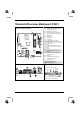
Übersicht/Overview Mainboard D1931 1= 2= Interne Anschlüsse und Steckplätze / Internal connectors and slots 21 Channel B Channel A 1 2 3 4 20 5 slot 4 slot 2 slot 3 slot 1 PCI Express x16 PCI Express x1 6 7 8 9 PCI 1 19 PCI 2 18 17 16 12 14 15 11 10 13 3= 4= 5= 6= 7= 8= 9= 10 = 11 = 12 = 13 = 14 = 15 = 16 = 17 = 18 = 19 = 20 = 21 = Diskettenlaufwerk / Floppy disk drive Stromversorgungsüberwachung / Power supply control Bedienfeld / Front panel Stromversorgung / Power supply IDE-Laufwe
Contents Übersicht/Overview Mainboard D1931 Mainboard D1931.............................................................................................................................1 Notational conventions...............................................................................................................1 Important notes .................................................................................................................................2 Information about boards ...................
Mainboard D1931 Your mainboard is available in different configuration levels. Depending on the configuration chosen, some of the hardware components described may not be available on your mainboard. Additional information Information on the BIOS Setup and additional descriptions of the drivers are contained: ● in the readme files on your hard disk ● on the driver floppy disks included ● on the CD "Drivers & Utilities Collection" or "Drivers & Utilities" or "ServerStart".
Important notes Important notes With the mainboard installed you must open the system to access the mainboard. How to dismantle and reassemble the system is described in the operating manual accompanying the system. Connecting cables for peripherals must be adequately shielded to avoid interference. ! Observe the safety notes in the operating manual of your system. Incorrect replacement of the lithium battery may lead to a risk of explosion.
List of features List of features Onboard features D1931-A Intel® 915G Chipset Board size µATX VGA ! Audio / 8-channel / S/PDIF Buzzer / int. Speaker Support LAN 1 Gbit / 100 Mbit / 10 Mbit LAN ASF / Alert-on-LAN / WoL / Boot SATA / ATA / RAID TM FireWire / HI-SPEED USB 2.
List of features Internal ports (continued) Front panel Audio (9-pin for headphone, microphone) AC'97 / High Definition Audio (Azalia) D1931-A 1/- FireWireTM * (9-Pin, Intel standard header) - USB Ports* (2.0, ~480 MB/s) 4 Serial Ports* (FIFO, 16550 compatible) Fan Connectors PSU** / CPU (FAN1) / AUX1 (FAN2) / AUX2 (FAN3) -/1/1/- SMBus Connector* (Case Temperature) - Cover monitoring* (Casing open) - BTX (24-pin) / ATX12V (20-pin) power supply 1/1 External ports VGA 1 Audio Mic.
List of features Special features Your mainboard is available in different configuration levels. Depending on the configuration, your mainboard is equipped with or supports the features described in the following. Silent Fan LT A controller regulates the processor fan in the PC and thus prevents unnecessary noise pollution. The controller operates independently of the operating system and the processor. Silent Drives Hard disks and optical drives (CD-ROM, CD-RW, DVD etc.
List of features Safe Standby With Safe Standby the content of the main memory is saved to the hard disk when the PC switches into the Standby mode. In case of an unexpected power failure, the content of the main memory is loaded during booting from the hard disk. Additional information is available on the Internet at www.fujitsusiemens.com/manageability.
Brief instructions on installing mainboard If you have purchased a separate mainboard, you can install the mainboard in your system in accordance with the following brief instructions. The activities described here assume a basic knowledge of PCs and cannot be carried out by a layperson. If you are not sure whether you have the necessary specialised knowledge, then leave this work to an expert. The illustrations of the system show examples of possible cases.
Brief instructions on installing mainboard ► Should no suitable connection field be provided in the case, then you must install the connection field (1) provided. Ensure the plate is aligned properly so that the connections are suitable for the mainboard later. ► Set the mainboard on the edge on which the connection field is located (2) and then insert the board in the case (3). Make sure that spacers in the housing are only mounted at points at which there are mounting holes in the mainboard.
Interfaces and connectors The positions of the interfaces and connectors are shown on page "Cover". The components and connectors marked are not necessarily present on the mainboard. External ports The positions of the external ports are shown on page "Cover".
Internal ports and connectors Graphics port Technical data Function: 2D/3D graphics controller, Dynamic Video memory Technology, 400 Mhz integrated 24-bit RAMDAC Features: Display Data Channel (DDC), 2 DVO channels (up to 165 megapixels per channel), dual-view support for ADD2 boards Screen resolution Depending on the operating system used, the screen resolutions in the following table refer to the mainboard screen controller.
Internal ports and connectors Audio front panel If you want to use the internal connection for the audio front panel for the front side of the system, then proceed as follows: ► Remove all plug-in jumpers from the audio front panel connection. ► Connect the cable for the audio front panel. i If you connect audio devices on both the front and the back of the system, you can only use the connections Line out and Microphone once each.
Pin assignment of internal ports Pin assignment of internal ports The pin assignment of some internal connections is shown in English in the following. i Some of the following connectors may be optional! Front panel Watch the poling of the LEDs. The positive pole of the connection cables is often indicated with a coloured wire.
Pin assignment of internal ports Pin Signal Pin Signal 1 3 5 7 9 11 GND "Stand by" LED + Key "Power On" LED + "Power On" LED + "Power On" LED "Stand by" LED (GND) "Message" LED + "Message" LED Key "HD" LED + "HD" LED GND Power-Button (low asserted) reserved Reset-Button (low asserted) 2 4 6 8 10 12 Speaker Key GND Speaker + Reserved Reserved 14 16 18 20 22 24 26 28 30 Key Password Skip "SCSI" LED Input (low asserted) "SCSI" LED Input (low asserted) Recover BIOS Key GND GND GND 13 15 17 19 21 23 2
Pin assignment of internal ports ATA interface 2 1 Pin Signal Pin Signal 1 3 5 7 9 11 13 15 17 19 21 23 25 27 29 31 33 35 37 39 Reset drive (low asserted) Data 7 (high asserted) Data 6 (high asserted) Data 5 (high asserted) Data 4 (high asserted) Data 3 (high asserted) Data 2 (high asserted) Data 1 (high asserted) Data 0 (high asserted) GND DRQ (high asserted) I/O write (low asserted) I/O read (low asserted) I/O ready (low asserted) DAK (low asserted) IRQ (high asserted) ADR 1 (high asserted) ADR 0
Pin assignment of internal ports Audio Input 1 Pin Signal 1 2 3 4 Left audio input Audio GND Audio GND Right audio input 1 Power control (system monitoring) Pin Signal 1 2 3 4 5 6 7 8 Power Guard Control PS FAN Control PS FAN Sense 1 Audio port front 2 Pin Signal Pin Signal 1 Micro input 2 Analogue GND 3 Micro bias 4 Analogue VCC 5 Right line output 6 Right line return 7 not connected 8 Key 9 Left line output 10 Left line return If the audio front panel is not used, yo
Pin assignment of internal ports USB - dual channel (Chipcard reader ready) 1 2 11 12 Pin Signal Pin Signal 1 Key 2 Chipcard reader on or not connected 3 VCC 1 or 3 4 VCC 2 or 4 5 Data negative 1 or 3 6 Data negative 2 or 4 7 Data positive 1 or 3 8 Data positive 2 or 4 9 GND 10 GND 11 Key 12 not connected 1 Fan 1, 2 and 3 Pin Signal 1 2 3 4 GND +12 V Fan sense Fan Control 16 - English A26361-D1931-Z120-1-7419, Edition 1
Pin assignment of internal ports 1 Power supply BTX (ATX compatible) 13 Pin Signal Pin Signal 1 2 3 4 5 6 7 8 9 10 11 12 +3,3 V (P3V3P) +3,3 V (P3V3P) GND +5V (VCC) GND +5V (VCC) GND Powergood (high asserted) +5 V Auxiliary (VCC Aux) +12 V (P12VP) +12 V (P12VP) 13 14 15 16 17 18 19 20 21 22 23 24 +3,3 V (P3V3P) -12 V (P12VN) GND PS on (low asserted) GND GND GND -5 V (P5VN) +5 V (VCC) +5 V (VCC) +5 V (VCC) GND Additional power supply ATX12 V 3 1 Pin Signal Pin Signal 1 3 GND +12 V 2 4 GN
Pin assignment of internal ports Jumper settings Your mainboard is equipped with jumpers. The positions of the jumpers are shown on page "Cover".
Add-on modules / Upgrading ! Exit energy-saving mode, switch off the system and remove the power plug from the mains outlet, before carrying out any of the procedures described in this chapter! Even when you have run down the device, parts of the device (e.g. memory modules, PCI extension boards) are still energised. Replacing processor Technical data ● Intel Pentium 4 with 533 or 800 MHz front side bus in the LGA775 design.
Replacing processor ► Remove the old processor (2) from the socket. a ► Insert the new processor in the socket so that the marking of the processor is aligned with the marking on the socket (a). 1 2 3 ► Fold down the frame (1). ► Press the lever downward (2) until it is hooked in again (3).
Replacing processor Mounting heat sink Be sure to use heat conducting material between the processor and the heat sink. If a heat conducting pad (rubber-like foil) is already applied to the heat sink, then use it. Otherwise you must apply a very thin layer of heat conducting paste. Heat conducting pads can only be used once. If you remove the heat sink, you must clean it and apply new heat conducting paste before you remount it.
Upgrading main memory Upgrading main memory Technical data Technology: DDR 333 or DDR 400 unbuffered DIMM modules 184-Pin; 2.5 V; 64 Bit, no ECC Size: 128 Mbytes to 4 Gbyte DDR 333 SDRAM 128 Mbytes to 4 Gbyte DDR 400 SDRAM Granularity: 128, 256, 512 or 1024 Mbyte for one socket ● A current list of the memory modules recommended for this mainboard is available on the Internet at: www.fujitsu-siemens.com/mainboards. At least one memory module must be installed.
Upgrading main memory Installing a memory module 2 2 ► Push the holders on each side of the memory slot outwards. ► Insert the memory module into the location (1). ► At the same time flip the lateral holders upwards until the memory module snaps in place (2). Removing a memory module 1 1 ► Push the clips on the right and left of the memory slot outward (1). ► Pull the memory module out of the memory slot (2).
Adding PCI Express cards Adding PCI Express cards The PCI Express x16 slot is intended for graphics cards, and the PCI Express x1 slot for PCI Express x1 cards. Adding PCI cards Technical data: 32 bit / 33 MHz PCI slots 5 V and 3.3 V supply voltage 3.3 V auxiliary voltage PCI bus interrupts - Selecting correct PCI slot i To achieve optimum stability, performance and compatibility, avoid the multiple use of IRQ Lines (IRQ sharing).
Adding PCI cards Multifunctional expansion cards or expansion cards with integrated PCI-PCI bridge: These expansion cards require up to four PCI interrupts: INT A, INT B, INT C, INT D. How many and which of these interrupts are used is specified in the documentation provided with the card.
Adding PCI cards Replacing the lithium battery In order to permanently save the system information, a lithium battery is installed to provide the CMOS-memory with a current. A corresponding error message notifies the user when the charge is too low or the battery is empty. The lithium battery must then be replaced.
BIOS update BIOS update When should a BIOS update be carried out? Fujitsu Siemens Computers makes new BIOS versions available to ensure compatibility to new operating systems, new software or new hardware. In addition, new BIOS functions can also be integrated. A BIOS update should always also be carried out when a problem exists that cannot be solved with new drivers or new software. Where can I obtain BIOS updates? The BIOS updates are available on the Internet at www.fujitsu-siemens.de/mainboards.
BIOS Recovery - Recovering System BIOS BIOS Recovery - Recovering System BIOS i ► All BIOS settings are reset to the default values. Open the casing as described in the operating manual. ► Set the switch for "Restore system BIOS" to ON. ► Close the casing as described in the operating manual. ► Insert a BIOS update floppy disk and start the PC. ► Note the signals issued from the loudspeaker.
Microcode Update Microcode Update What is a microcode update? As there are no drivers for processors, Intel offers the possibility from the P6 family (Pentium Pro) on to update the command set (microcode) of the processor. This enables minor errors to be corrected and the performance to be increased. To guarantee the best possible performance and error-free operation, Intel recommends updating the microcode for every new processor.
Drivers Drivers Only when no drivers are installed on your system, or you want to update these, proceed as follows: ► Insert the CD "Drivers & Utilities Collection" into the CD-ROM drive. ► If the CD does not start automatically, run the START.EXE programme in the main directory of the CD. ► Select DeskUpdate - Fully automatic installation. ► Follow the instructions on screen.
Annex Electrical Properties Loadability for connections and fuses i Make sure that the connected devices do not overload the connections. Fuse no. Fuse Connection Maximum loadability 1 750 mA 2 2000 mA 3 2000 mA Keyboard Mouse VGA port USB port 1 USB port 2 USB port 3 USB port 4 USB port 5 USB port 6 USB port 7 USB port 8 Not specified Not specified Not specified 500 mA 500 mA 500 mA 500 mA 500 mA 500 mA 500 mA 500 mA The fuses on this mainboard can be used several times (polyfuses).
APM and ACPI system status, energy-saving modes The specifications apply to the onboard components and represent the least favourable case. In addition, at least 350 mA is required for PCI on 3.3 V, and 500 mA per connected device for USB on 5 V.
Mainboard Revision and BIOS Version Mainboard Revision and BIOS Version The compatibility, e.g. with new processors, can be independent of the BIOS version or the revision status of the mainboard used. The CPU and BIOS compatibility lists are available on the Internet at www.fujitsu-siemens.de/mainboards. Mainboard Revision The revision status of the mainboard exactly identifies which mainboard you have.
Error messages This chapter contains error messages generated by the mainboard. Available CPUs do not support the same bus frequency - System halted! Memory type mixing detected Non Fujitsu Siemens Memory Module detected - Warranty void There are more than 32 32 RDRAM devices in the system Check whether the system configuration has changed. If necessary, correct the settings.
Error messages DMA test failed EISA CMOS not writable Extended RAM Failed at offset: nnnn Extended RAM Failed at address line: nnnn Failing Bits: nnnn Fail-Safe Timer NMI failed Multiple-bit ECC error occurred Memory decreased in size Memory size found by POST differed from EISA CMOS Single-bit ECC error occurred Software NMI failed System memory exceeds the CPU’s caching limit System RAM Failed at offset: nnnn Shadow RAM Failed at offset: nnnn Switch the device off and on again.
Error messages Missing or invalid NVRAM token Switch the device off and on again. If the message is still displayed, please contact your sales outlet or customer service centre. Monitor type does not match CMOS - RUN SETUP Correct the entry for the monitor type in the Main menu of the BIOS Setup. On Board PCI VGA not configured for Bus Master In the BIOS Setup, in the Advanced menu, submenu PCI Configuration, set the Shared PCI Master Assignment entry to VGA.
Error messages System battery is dead - Replace and run SETUP Replace the lithium battery on the mainboard and redo the settings in the BIOS Setup. System Cache Error - Cache disabled Switch the device off and on again. If the message is still displayed, please contact your sales outlet or customer service centre. System CMOS checksum bad - - Default configuration used Call the BIOS Setup and correct the previously made entries or set the default entries.
Glossary The technical terms and abbreviations given below represent only a selection of the full list of common technical terms and abbreviations. Not all technical terms and abbreviations listed here are valid for the described mainboard.
Glossary Data) SMBus System Management Bus SVGA Super Video Graphic Adapter TEMP Temperature USB Video Graphic Adapter USB Universal Serial Bus VGA Video Graphic Adapter WOL Wake On LAN A26361-D1931-Z120-1-7419, Edition 1 English - 39