C141-E124-01EN MAN3184, MAN3367, MAN3735 SERIES DISK DRIVES SCSI LOGICAL INTERFACE SPECIFICATIONS
This Product is designed, developed and manufactured as contemplated for general use, including without limitation, general office use, personal use and household use, but is not designed, developed and manufactured as contemplated for use accompanying fatal risks or dangers that, unless extremely high safety is secured, could lead directly to death, personal injury, severe physical damage or other loss (hereinafter “High Safety Required Use”), including without limitation, nuclear power core control, airpl
FOR SAFE OPERATION Handling of This manual This manual contains important information for using this product. Read thoroughly before using the product. Use this product only after thoroughly reading and understanding especially the section “Important Alert Items” in this manual. Keep this manual handy, and keep it carefully. FUJITSU makes every effort to prevent users and bystanders from being injured or from suffering damage to their property. Use the product according to this manual.
Related Standards Specifications and functions of products covered by this manual comply with the following standards. Standard (Text) No. ANSI X3. 131-1986 ANSI X3. 131-1994 X3T9.2/85-52 Rev 4.B Name American National Standard for Information Systems --- Small Computer System Interface (SCSI) American National Standard for Information Systems --- Small Computer System Interface-2 (SCSI-2) COMMON COMMAND SET (CCS) of the Small Computer System Interface (SCSI) X3T9.
REVISION RECORD Edition Date published 01 March, 2001 Revised contents Specification No.
PREFACE This manual explains concerning the MAH3182/MAH3091, MAK3728 and MAJ3364/MAJ3182/ MAJ3091 series 3.5 inch hard disk drives with internal SCSI controller. The purpose of this manual is to provide specifications of each command and detailed explanations of their functions for use of these magnetic disk drives incorporated into user systems, and to present the information necessary for creating host system software.
Chapter 6 Disk Media Management This chapter describes the procedure for initializing the disk media, methods of treating media defects and data recovery methods for the disk drives. Glossary The glossary explains technical terms which are necessary to the reader’s understanding when reading this manual. List of Abbreviations This list shows the full spelling of abbreviations used in this manual.
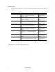
Note 2: Typical model name Type model name MAH3182 MAH3091 MAK3728 MAJ3364 MAJ3182 MAJ3091 Model name MAH3182MP, MAH3182MC MAH3091MP, MAH3091MC MAK3728MP, MAK3728MC MAJ3364MP, MAJ3364MC MAJ3182MP, MAJ3182MC MAJ3091MP, MAJ3091MC Warning Indications The following warning indications are shown in this manual to prevent the user and other nearby persons or property from being injured or damaged. Note “Note” indicates the most effective method of use or information that is of value to the user.
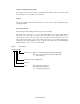
Manual Organization Product/ Maintenance Manual SCSI Physical Interface Specifications SCSI Logical Interface Specifications (This Manual) 1. 2. 3. 4. 5. 6. 7. 8. General Description Specifications Data Format Installation Requirements Installation Diagnostics and Maintenance Error Analysis Principle of Operation 1. SCSI Bus 2. SCSI Messages 3. Error Recovery 1. 2. 3. 4. 5. 6.
CONTENTS page CHAPTER 1 COMMAND PROCESSING .................................................................................. 1-1 1.1 Command Format ......................................................................................................... 1-1 1.2 Status Byte .................................................................................................................... 1-7 1.3 Outline of Command Processing.............................................................................
2.1.2 Operation mode setting ................................................................................................. 2-5 2.2 Look-Ahead Cache Feature .......................................................................................... 2-7 2.2.1 Caching operation ......................................................................................................... 2-7 2.2.2 Caching parameters............................................................................................
3.1.19.1 PERSISTENT RESERVE OUT service actions ........................................................... 3-66 3.1.19.2 PERSISTENT RESERVE OUT parameter list............................................................. 3-67 3.1.20 REPORT LUNS (A0) ................................................................................................... 3-69 3.1.21 REPORT DEVICE IDENTIFIER (A3) ........................................................................ 3-71 3.1.
4.1.7 Control mode parameters (page code = 0A) ................................................................ 4-29 4.1.8 Notch parameter (page code = 0C) ............................................................................... 4-33 4.1.9 Informational exceptions control page (page code = 1C) ............................................. 4-35 4.1.10 Additional error recovery parameters (page code = 21) ............................................... 4-39 4.2 Log Parameters .................
4.2.9 Application client page (X'0F') ..................................................................................... 4-58 4.2.9.1 General usage application client parameter data (Page 0F, Code 0000-003F) ............. 4-59 4.2.10 Self-test result page (X'10') ........................................................................................... 4-59 4.2.10.1 Self-test result parameter data (Page 10, Code 0001-0014).......................................... 4-60 4.2.
FIGURES Pages 1.1 6-Byte CDB Basic Format ....................................................................................................... 1-2 1.2 10-Byte CDB Basic Format ..................................................................................................... 1-2 1.3 12-Byte CDB Basic Format ..................................................................................................... 1-3 1.4 Status Byte .....................................................................
4.1 MODE SELECT parameters: read/write error recovery parameters ........................................ 4-2 4.2 MODE SELECT parameters: disconnect/reconnect parameters .............................................. 4-11 4.3 MODE SELECT parameters: format parameters .................................................................... 4-15 4.4 MODE SELECT parameters: drive parameters ...................................................................... 4-19 4.
CHAPTER 1 COMMAND PROCESSING 1.1 Command Format 1.2 Status Byte 1.3 Outline of Command Processing 1.4 Command Queuing Function 1.5 UNIT ATTENTION Condition 1.6 Sense Data Hold State 1.7 Command Processing Exceptions 1.8 Data Block Addressing This chapter describes the basic logical specifications of the IDD command processing functions. Note: 1.1 The IDD operates as the target (TARG) on the SCSI bus.
Bit Byte 7 6 5 0 3 LUN Logical Block Address 3 Logical Block Address (LSB) 4 Transfer Data Length 5 Control Byte Figure 1.
Bit 7 Byte 6 5 4 0 3 2 1 0 0 0 0 0 0 0 Operation Code 1 LUN 0 0 2 Logical Block Address (MSB) 3 Logical Block Address 4 Logical Block Address 5 Logical Block Address (LSB) 6 Transfer Data Length (MSB) 7 Transfer Data Length (LSB) 8 Transfer Data Length (MSB) 9 Transfer Data Length (LSB) 10 0 0 0 11 0 0 Control Byte Figure 1.3 12-Byte CDB Basic Format The meanings of each of the fields in the CDB are explained below.
b. Command code Command code specifies the type of command in each group. (2) LUN (Logical Unit Number) This field specifies the address of the logical unit (device) connected under the TARG in cases where the IDENTIFY message is not used. If the IDENTIFY message is used, the value of the CDB’s LUN field is ignored when the LUN is specified. Note: It is possible that the definition of this field may be changed in future SCSI standards.
b. Transfer byte length or parameter list length When this field is specified as the “Transfer Byte Length” or “Parameter List Length,” that command specifies data length to be transferred between the INIT and the IDD, expressed as the number of bytes. When 0 is specified in this field, data transfer is not executed, except in cases where it is expressly stated in the individual command specifications in Chapter 3.
Note: It is possible that bits 7 and 6 of the control byte will be used in future product specifications as an inherent control field. It is recommended that zeros be specified in this field. (6) Handling an illegal CDB If there is an error in the contents of a description (specification) in the CDB, or if there is an error in the specifications in parameters transferred from the INIT by CDB specifying, that command ends with a CHECK CONDITION status.
1.2 Status Byte Figure 1.4 shows status byte format and the type of status that the IDD supports. The status byte is one byte of information sent from the TARG to the INIT in the STATUS phase when one command is completed, and notifies the INIT of the results of the command’s execution. The status byte is also sent even in cases when the TARG is in a state which it makes it impossible for it to execute the command when it receives a request for an input/output operation.
(1) GOOD status This status indicates that execution of the command ended normally. (2) CHECK CONDITION status This status is reported in the following cases a) to c). The IDD generates sense data when it reports this status and indicates the detailed cause. The INIT issues a REQUEST SENSE command when it receives this status and should sample sense data.
(5) INTERMEDIATE status This status indicates that a command which specifies a link (except the last command in a group of linked commands with “1” as its Link bit) has been completed normally. If a command which specifies a link is completed abnormally and the CHECK CONDITION status or RESERVATION CONFLICT status is reported, the command link is broken an the subsequent linked commands are not executed.
1.3 Outline of Command Processing 1.3.1 Single commands Following shows single command processing examples which are the most basic operations on the SCSI bus. Furthermore, if disconnect processing is permitted, it may be accompanied by disconnect/reconnect processing during the command execution, depending on the type of command, but this operation is omitted in the following explanation. The disconnect function is described in Section 1.3.3.
1.3.2 Command link The command link function is a function which causes the TARG to execute continuous processing of multiple commands. Following shows examples of command link processing. 1) The INIT sets the initial values for the command in the command pointer, data pointer and status pointer. 2) Obtaining the SCSI bus usage, selection of the TARG and specification of the LUN by the IDENTIFY message are the same as in the case of single command.
Table 1.
1.3.3 Disconnect/reconnect processing When processing is performed by the TARG during the command execution process which does not require operation on the SCSI bus, the TARG can return the SCSI bus to the BUS FREE phase temporarily by disconnect processing and execute command internally. Through this function, the INIT is enabled to process multiple commands on the SCSI bus.
Table 1.2 Types of Command and Disconnect Processing Commands with executing disconnect processing. (Note 2) Commands without executing disconnect processing.
other than cases where the command is in a queue, disconnect processing may not be executed depending on the processing content specification of the command. (2) Basic disconnect processing procedure Disconnect processing is executed basically by the following processing procedure. 1) If the IDD judges that it is possible for it to disconnect from the SCSI bus during execution of a command, it sends a DISCONNECT message to the INIT and enters the BUS FREE phase.
b. If disconnecting after the final data transfer is completed In the case of a disconnect after transfer of all the data necessary for execution of a command has been completed normally, (example: a WRITE command), the IDD sends a DISCONNECT message after sending the SAVE DATA POINTER message. After that, the IDD executes reconnection processing and enters the STATUS phase immediately and reports the status byte without requesting a data transfer.
command necessary for reconnection processing and generates sense data indicating ABORTED COMMAND[=B]/Select /Reselect failure[=45-00]. 2) If the INIT rejects the IDENTIFY message, or if it rejects the SIMPLE message when executing a tagged queuing command, the IDD clears the command that was being executed during reconnection processing and enters the BUS FREE phase. In this case, the IDD generates sense data indicating ABORTED COMMAND[=B]/Message error[=43-00].
The data transfer mode set with the INIT once is effective until a RESET condition occurs or until a TARGET RESET message is issued by any INITs. Therefore, in order for the INIT to avoid overhead time for message exchange, the INIT should not send the WIDE DATA TRANSFER REQUEST message and the SYNCHRONOUS DATA TRANSFER REQUEST message or PARALLEL PROTOCOL REQUEST message to the TARG each time the SELECTION phase is executed.
1.4 Command Queuing Function The IDD equips a command queuing function. Through queuing of commands, the IDD can receive multiple commands in advance and execute them. There are two methods used in the queuing function, tagged and untagged. In tagged queuing, the IDD can receive multiple commands from each INIT. In untagged queuing, the IDD can receive a single command from each INIT. Both queuing methods are possible for the IDD, but an INIT can use only one queuing method at a time.
• If disconnect processing is impossible. If disconnect processing is impossible because the INIT which issued the command does not meet the conditions for permitting a disconnect (see Section 1.3.3), or if the DISCONNECT message is rejected by the INIT even though it meets the conditions for permitting a disconnect, the IDD responds with a BUSY status without queuing the received command except the case described in item 1) in following Note during executing or queuing command already.
1.4.2 Tagged queuing Through the tagged queuing function, the IDD can receive multiple commands from the same INIT or from different INITs until the command queue is full. The number of commands that it is possible to receive by the IDD is 128 maximum, without relation to the INIT. When the IDD receives a new command, if the command queue is full, it responds to the new command with the QUEUE FULL status.
When “0” is specified in the QErr bit, the IDD enters any one of a number of sense hold states, and when this state is released, it continues to execute the commands in the queue. The IDD queues any commands received from other INITs while it is in the sense hold state, but during this period, execution of all the commands in the queue is interrupted. If “1” is specified in the QErr bit, if the IDD enters any one of a number of sense hold states, the queue is cleared after the sense hold state is released.
1.5 UNIT ATTENTION Condition The UNIT ATTENTION condition is a function used to notify the INIT asynchronously of an event (status change) that has occurred in the TARG or logical unit. 1.5.1 Generation of the UNIT ATTENTION condition Events which cause a UNIT ATTENTION condition to be generated are one of the following.
1.5.2 Response and Release Condition at UNIT ATTENTION Condition Hold State A UNIT ATTENTION condition generated by the IDD by the occurrence of the previously mentioned events is held individually for each INIT and it is held until it is released by the INIT it is held for issuing the commands specified below.
(2) INQUIRY command The INQUIRY command is executed normally, but the UNIT ATTENTION condition is not cleared. (3) REQUEST SENSE command One of the following operations is performed depending on whether or not the IDD is in the sense data hold state (shown in Section 1.6). a. In the case of a Sense Data Hold state The IDD executes the REQUEST SENSE command normally and sends the sense data which are being held to the INIT. In this case, the UNIT ATTENTION condition is not cleared. b.
1.6 Sense Data Hold State 1.6.1 Sense data hold condition The IDD generates sense data if any of the following conditions occurs and enters the sense data hold state until the conditions for cancellation, described in Section 1.6.2, are established. The sense data which are generated, are held for each individual INIT that issued the applicable command. The sense data hold state is also maintained individually for each INIT which is their object.
1.6.2 Response and release conditions at sense data hold state The response of the IDD when it receives a new command while it is in the sense data hold state, and conditions for releasing the sense data hold state are shown below. 1) If a command is issued to the logical unit in the sense data hold state by the INIT which is the object of sense data holding.
1.7 Command Processing Exceptions 1.7.1 Overlapping commands If the following state occurs, the IDD recognizes that overlapping commands have been generated and the command is terminated abnormally. 1) During the IDD is executing or queuing an untagged command, the INIT that issued that command before the completion of the command execution issues either an untagged command or a tagged command.
1.7.2 Illegal LUN specification The logical unit number (LUN) supported by the IDD is LUN = 0 only. If a LUN other than this (1 to 7) is specified, the IDD performs one of the following operations, depending on the type of command issued at that time. 1) The INQUIRY command is executed normally even if the LUN specification is illegal. However, byte 0 of the “Standard INQUIRY Data” (“Qualifier” field and “Device Type Code” field) transferred to the INIT for that command indicates X ‘7F.
(1) General response in not ready state The IDD reports a CHECK CONDITION status for a command, except in cases where the command is one of the commands in item (2). The sense data generated at this time depends on the state of the IDD, as shown in Table 1.3. Table 1.3 IDD State (2) Sense data in not ready state Sense Key Spindle motor not rotating at normal speed. NOT READY Reading system information have not completed. Reading system information failed.
(3) Operation if formatting is not completed normally While the FORMAT UNIT command is not being executed after a change in data format related parameters by the MODE SELECT command, if the FORMAT UNIT command is terminated abnormally for any reason (example: power cut off or RESET condition), the data on the disk media cannot be accessed normally. In this case, the IDD reports a CHECK CONDITION status for the command accessing the disk media.
(2) Recovery procedures for disk drive errors The IDD executes error recovery listed in Table 1.5 for an error detected during access to data on the disk. Note that the recovery increases command processing time because of rotation delay for repositioning to the data block on the disk or initialization of the positioning control system.
1.7.6 Reset processing The INIT can reset the SCSI bus with following. x x x x x RESET condition TARGET RESET message CLEAR TASK SET message ABORT TASK SET message ABORT TASK message The RESET condition resets all the SCSI devices connected on the same SCSI bus. The IDD is initialized to the same state as when its power is switched on by the RESET condition, with the currently executed command as well as all the commands in the queue cleared.
Table 1.6 Type of command Reset processing during write Halting process of command execution WRITE WRITE EXTENDED WRITE AND VERIFY SEND DIAGNOSTIC (Write/Read Test) WRITE LONG WRITE SAME Data blocks which are currently being written are processed normally, including the ECC portion, and execution of the command is terminated at the point when that processing is completed. Not all the data transferred from the INIT to the IDD will necessarily be written to the disk media.
1.7.7 Fatal hardware errors (1) Self-diagnostic errors If a hardware fatal error is detected during the initial self-diagnosis, in off-line self diagnosis or in on-line self-diagnosis (SEND DIAGNOSTIC command), rotation of the spindle motor will be halted. When in this state, the IDD reports the CHECK CONDITION status for all input/output operation requests except the REQUEST SENSE command. The sense data reported at this time indicate HARDWARE ERROR [=4] / Diagnostic failure on component “nn” [=40-nn].
1.8 Data Block Addressing 1.8.1 Definition of data space The IDD manages the data storage area on the disk drive in the following 2 types of data space. x x User space: user data storage area System space: IDD exclusive area Within these 2 areas, the user can clearly access the user space. The data format and defect management methods in this space are the same and it is possible to access this space by logical data block addressing described in Section 1.8.2.
Physical cylinder [System space] Track 0 Cylinder 0 Track 0 Cylinder 1 Cell 0 Track 0 Zone 0 Cylinder (a-1) Cell 1 [User space] Track 0 Alternate cylinder (b-1) (b cylinders) Zone 1 Cylinder (a-1) Zone (x-1) Alternate cylinder (c cylinders) Last cylinder (d-1) (Last cylinder) Figure 1.
1.8.2 Logical block addressing The IDD uses logical data block addressing which is not dependent on the disk drive’s physical structure as the method of data access on the disk medium. The IDD makes correspondence between each physical sector and each logical data clock address during formatting. Access to the data on the disk medium is performed in logical data block units and the INIT specifies the logical data block address that is its object during access.
CHAPTER 2 DATA BUFFER MANAGEMENT 2.1 Data Buffer 2.2 Look-Ahead Cache Feature 2.3 Write Cache In this chapter, the configuration of the data buffer with which the IDD is equipped, its operation and the operation of the cache feature are described. 2.1 Data Buffer 2.1.1 Data buffer configuration and basic operation The IDD is equipped with a data buffer, which makes it possible to efficiently execute data transfer operations between INIT (initiator) and a disk drive.
Segment Segment 7 Segment 6 Segment 5 Segment 4 Segment 3 Segment 2 Segment 1 Segment 0 Disk Media Valid Data INIT Writeo Writeo mRead mRead Figure 2.1 Data buffer configuration (in the case of 8 cache segments) The basic functions and operations of the data buffer in a read operation and a write operation are shown below. (1) Read operation Data read from the disk media are temporarily stored in the data buffer.
6) When transfer of all the specified data is completed, the IDD reports the status and terminates the command. Note: In order to avoid frequent repetition of the disconnect/reconnect processing after data transfer starts on the SCSI bus, and avoid the occurrence of data overruns, it is necessary to set the buffer full ratio (see Section 2.1.2) of the MODE SELECT parameter so the difference in the data transfer rates between the INIT (SCSI bus) and the disk drive is maintained in a good balance. Figure 2.
3) If the data transfer rate of the INIT (SCSI bus) is lower than the data transfer rate of the disk drive, since the data pre-fetch of data that are to be written to that data block is not completed, it may not be possible to write the data continuously to the disk (data underrun). In this case, the IDD waits one disk revolution while continuing to pre-fetch data from the INIT, then repositions the block that caused the data underrun and continues the writing of data to the disk.
2.1.2 Operation mode setting (1) MODE SELECT parameter In order to make it possible to control from the INIT the reconnection processing start timing for executing data transfers with the SCSI bus in read and write operations, the IDD is provided with the MODE SELECT parameter (Disconnect/Reconnect Parameter: Page code = 2) shown in Figure 2.4. The user can set the optimum operating state in the system environment as necessary.
is performed when it becomes possible to transfer 2 blocks of data [16 x (32/256)], from the data buffer. b. Buffer empty ratio This parameter specifies the timing for the IDD to start reconnection when it is requested by the INIT to transfer data in the WRITE, WRITE EXTENDED or WRITE AND VERIFY command. In a write operation, after the IDD receives a command, the IDD begins transferring data (data pre-fetch) while locating the position of the target data blocks on the disk media in parallel.
2.2 Look-Ahead Cache Feature In order to use the data buffer more effectively and improve the disk drive's effective access speed, the IDD is equipped with a simple cache feature called a "Look-Ahead Cache Feature." The LookAhead cache feature is an effective, simple cache function for an INIT which reads data block groups on the disk media sequentially using multiple commands. 2.2.
b) Data which have been hit by the READ or READ EXTENDED command and transferred to the INIT once are also objects of caching as long as they are not invalidated. c) Data transferred from the INIT and written to the disk media by the WRTTE and WRITE EXTENDED command are objects of caching. d) Data transferred from the INIT and written to the disk media by the WRITE AND VERIFY command is not the objects of caching.
2.2.2 Caching parameters The IDD supports the MODE SELECT parameters (caching parameters: page code = 8) shown in Figure 2.5 for controlling the cache feature. See Section 4.1 concerning details of the MODE SELECT parameters.
2.2.3 Look-Ahead operation, Look-Ahead volume 1) Excluding the conditions in 3) and 4) for the amount of data specified as the minimum prefetch volume, data are read for look-ahead irrespective of track boundaries or cylinder boundaries. Commands which are already in the queue or commands which are newly received while a look-ahead operation is in progress, are executed after the look-ahead operation is completed.
2.3 Write Cache The IDD is equipped with a write cache function in order to reduce the INIT's command processing time. If that operation is permitted by the MODE SELECT command (caching parameters: Page code = 8, WCE bit), at the point when the IDD completes the transfer of all data specified in the WRITE or WRITE EXTENDED command, it reports the GOOD status and terminates the command.
CHAPTER 3 COMMAND SPECIFICATIONS 3.1 Control/Sense Commands 3.2 Data Access Commands 3.3 Format Commands 3.4 Maintenance, Diagnostic Commands This chapter describes detailed specifications of the SCSI commands which the IDD is equipped with and how to use them. 3.1 Control/Sense Commands 3.1.
3.1.2 INQUIRY (12) Bit Byte 7 6 5 4 0 3 2 1 0 0 0 CmdDt EVPD 0 0 0 0 Flag Link X‘12’ 1 LUN 0 2 Page Code/Operation Cpde 3 0 0 0 4 0 0 Transfer Byte Length 5 0 0 0 0 0 This command transfers the information showing the IDD's characteristics (INQUIRY data) to the application client. This command is executed immediately without queuing in a system which issues only commands with no tags or links.
If bytes 1, the "EVPD (enable vital product data)" bits, the "CmdDt (Command Support Data)" bits, and byte 2, the "Page code" field in the CDB are enabled only in the case that transfer of the SCSI-2/SCSI-3 mode's INQUIRY data is specified. In the case of the SCSI-1/CCS mode, zero must be set in these bits and in this field. And if both the "EVPD" and "CmdDt" bits are one, this command is terminated by a CHECK CONDITION status (ILLEGAL REQUEST [=5] / Invalid Field in CDB [=24-00]).
Bit 7 6 5 4 3 2 1 SCSI mode 0 Byte 0 Qualifier (0, 0, 0) or (0, 1, 1) RMB 0 0 0 RMB 0 0 0 1 2 3 AENC TrmIOP 0 0 0 1 AERC Obsolete 0 0 4 0 1 0 0 SCCS 0 0 0 0 (Reserved) 5 6 0 0 BQue EncServ 0 0 0 0 RelAdr WBus32 0 0 RelAdr Obsolete 0 0 7 8 9 ~ ~ ~ ~ ~ ~ 15 16 17 31 32 33 34 35 36 37 Device Type Code (0, 0, 0, 0, 0) or (1, 1, 1, 1, 1) Reserved 0 0 0 0 0 Device Type Code 0 0 0 0 0 Version X’ 01’ (SCSI-1) X’ 02’ (SCSI-2) X’ 03’ (SPC) or X’ 04’ (SPC-2) Response Data Format 0 0 0 0 0 1 0
a. Qualifier field (0,0,0): The specified logical unit shows the type of input/output device shown in the "Device Type Code" field. Even if this code is reported, it does not mean that that logical unit is in the ready state. (0,0,1): The specified logical unit shows the type of input/output device shown in the "Device Type Code" field, but it shows that an actual input/output device is not connected to that logical unit. The IDD does not report this code.
f. Additional data length This field shows the length of the INQUIRY data (byte length) after byte 5. This value shows the length in the INQUIRY data held by the IDD without relation to the specification in the transfer byte length field in the CDB, and is always X‘5B’ (total data length = 96 bytes). g.
Bque CmdQue 0 0 1 1 0 1 0 1 Description No command queuing of any kink supported Command queuing with all types of task tags supported Basic task set model supported Illegal combination of BQue and CmdQue bits - VS (Vendor specific): Not defined x [0] SCSI-2 mode [Byte 3] - AENC (Asynchronous event notification capability): Asynchronous condition notify function - TrmIOP (Terminate I/O process): TERMINATE I/O PROCESS message [Byte 6] - DualP (Dual port): Dual port function - Port: Connection port, '0
i. Product ID field The product's model name is displayed in left-justified ASCII code in this field. j. Product Revision field The IDD's microcode version number is displayed in ASCII code in this field. k. Device Serial Number field The value following byte 4 of the device serial number in the VPD information is indicated in this field. Higher order digits which do not contain valid numbers are filled with ASCII code spaces (X '20'). l.
(6) BYTE Code Description 58 to 59 OX00, OX40 SAM2 60 to 61 OX0B, OX18 SPI3 T10/1302D rev10 62 to 63 OX01, 0X3C SPC ANSI X3.301: 1997 64 to 65 OXS01, OX9B SBC T10/0996 rev08C 66 to 67 OX00, OX00 - 68 to 69 OX00, OX00 - 70 to 71 OX00, OX00 - 72 to 73 OX00, OX00 - Command Support Data Figure 3.2 shows the format and contents of the command support data transferred to the INIT by this command if "0" is specified in the "EVPD" bit and "1" is specified in the "CmdDt" bit.
b. Support This field indicates the value defined below. "Support" Bit 2 1 0 0 0 0 0 0 1 0 1 0 0 1 1 1 0 0 1 0 1 1 1 0 1 1 1 Description Data about the requested SCSI operation code is not currently available. The device server does not support the tested SCSI operation code. All data after byte 1 is undefined. Reserved The device server supports the tested SCSI operation code in conformance with an SCSI standard.
(7) VPD information When "1" is specified in the "EVPD" bits of the CDB, the VPD information described below is transferred to the INIT by this command. The INIT specifies the type of VPD information required in the "Page code" field of the CDB. The type of VPD information supported by the IDD and its page code number are as shown below.
Byte 4 and subsequent bytes list all the VPD information page codes supported by the IDD, with the VPD page code indicated in ascending order in each byte. b. Device serial No. This VPD information reports the device serial number of the IDD. The format of this VPD information is shown in Figure 3.4. Bit 7 Byte 0 6 5 4 3 Qualifier 2 1 0 Device Type Code 1 X‘80’ (Page Code) 2 X‘00’ 3 X‘0C’ (Page Length) 4 5 ~ ~ ~ ~ Device Serial No. (ASCII) ~ ~ 15 Figure 3.
c. Operation mode This VPD information reports the IDD's current operation mode. The format of this VPD information is shown in Figure 3.5. Bit Byte 7 0 6 5 4 3 Qualifier 2 1 0 RSRTY 0 Device Type Code 1 X‘C0’ (Page Code) 2 X‘00’ 3 X‘04’ (Page Length) 4 0 0 0 WDTR UNTAIN SDTR 5 PHSCRC AGD ACE 0 0 0 6 X‘xx’ (Spindle Motor Start Delay Timing) 7 X‘00’ (Reserved) Figure 3.
3.1.3 READ CAPACITY (25) Bit Byte 7 6 5 0 4 3 2 1 0 0 0 0 0 0 X‘25’ 1 LUN 2 Logical Block Address (MSB) 3 Logical Block Address 4 Logical Block Address 5 Logical Block Address (LSB) 6 0 0 0 0 0 0 0 0 7 0 0 0 0 0 0 0 0 8 0 0 0 0 0 0 0 PMI 9 0 0 0 0 0 0 Flag Link This command transfers information related to the disk drive's capacity and the data block size to the INIT.
By using this command with the "PMI" bit specified as "1", the INIT can search for usable data space continuously without being interrupted by data transfers for alternate sector processing or switching of cylinders. The format of the data transferred to the INIT by this command is shown in Figure 3.6.
3.1.4 CHANGE DEFINITION (40) Bit Byte 7 6 5 4 3 2 1 0 0 0 0 0 0 0 0 0 0 Save 0 X‘40’ 1 LUN 2 0 0 0 3 0 4 0 0 0 0 0 0 0 0 5 0 0 0 0 0 0 0 0 6 0 0 0 0 0 0 0 0 7 0 0 0 0 0 0 0 0 0 Flag Link SCSI Level 8 Parameter List Length 9 0 0 0 0 0 This command changes the IDD's SCSI level and the operation mode.
If zero is specified in the "SCSI Level" field, the IDD operates at the current SCSI level without changing the SCSI level. However, if the correct operation mode parameter (described later) is transferred at the same time, the IDD changes its operation mode. The total byte length of the operation mode parameter transferred by the INIT with this command is specified in the "Parameter List Length" field in CDB byte 8.
(1) Header a) Bytes 0 to 2 X '00' must be specified in this field. b) Parameter length The parameter list length in byte 4 and subsequent bytes which follows the header must be specified in this field. The parameter list length supported by the IDD is X '04' and the INIT must not specify a value other than X '04' in this field.
c) SDTR (synchronous data transfer request) Specifies whether or not it is permitted for the TARG to request a synchronous mode data transfer. "1" (Permitted) : After the power is switched on, after a RESET condition occurs or when the first command is received following reception of a BUS DEVICE RESET message, if a SYNCHRONOUS DATA TRANSFER REQUEST (SDTR) message is not sent by the INIT, the IDD sends the SDTR message and attempts to establish synchronous mode data transfer.
g) AGD (AIP generation disabled) This specifies whether or not it is permitted to generate AIP (Asynchronous Information Protection). "1" (Prohibited): Prohibited generation "0"*(Permitted): Permitted generation * Set at shipping time h) RTD (reselection timeout delay) This specifies the reselection timeout delay time.
3.1.5 MODE SELECT (15) Bit Byte 7 6 5 4 3 2 1 0 PF 0 0 0 SP 0 X‘15’ 1 LUN 2 0 0 0 0 0 0 0 0 3 0 0 0 0 0 0 0 0 0 Flag Link 4 5 Parameter List Length 0 0 0 0 0 This command performs setting and changing of each type of parameter related to disk drive physical attributes, data format, timing of SCSI bus disconnect/reconnect processing and error recovery procedures, etc.
If a "Header," "Block Descriptor" or any "Page Descriptor" cannot be transferred with all the defined length because the total defined length of the MODE SELECT parameters actually transferred from the INIT do not match the value specified in the "Parameter List Length" field, or if the total of the MODE SELECT parameter's defined length transferred from the INIT exceeds the value specified in the "Parameter list length" field, this command is terminated with a CHECK CONDITION status (ILLEGAL REQUEST [=5] /
Current values MODE SELECT [Command to all INITs] Pages: 1, 2, 7, 8, A, C, 1C, 21 Power-on RESET condition Save values TARGET RESET message [Command to all INITs] MODE SELECT (SP=1) Pages: 1, 2, 7, 8, A, 1C, 21 Power-on [Command to all INITs] [Command to all INITs] FORMAT UNIT Block descriptor Pages: 3, 4 Power-on RESET condition TARGET RESET message Default values [Command to all INITs] Pages: 1, 2, 7, 8, A, C, 1C, 21 Figure 3.
If the IDD performs rounding processing ("rounding up" or "rounding down") of parameter values specified by the INIT, in some cases a "CHECK CONDITION" status (RECOVERED ERROR [=1] / Rounded parameter [37-00]) is reported, and in some cases it is not reported. Whether or not a "CHECK CONDITION" status is reported is determined by the type of "rounding up" or "rounding down" and the conditions.
Header Bit 7 Byte 6 5 4 3 0 X‘00’ 1 X‘00’ (Media Type) u 2 0 3 u 0 0 2 1 0 0 0 0 1 0 X‘00’ or X‘08’ (Product Descriptor Length) Block Descriptor Bit 7 Byte 6 5 4 3 2 0 Data Block Count (MSB) 1 Data Block Count 2 Data Block Count 3 Data Block Count (LSB) 4 X‘00’ 5 Data Block Length (MSB) 6 Data Block Length 7 Data Block Length (LSB) Page Descriptor Bit Byte 0 Page Header 7 6 0 0 5 4 3 2 1 0 Page Code 1 Page Length 2 ~ ~ ~ ~ Parameter Field
a. Header x Media type X '00' (default type) must be specified in this field. x Byte 2 Bits 7 and 4 of this field have meaning only in the header transferred to the INIT by the MODE SENSE and MODE SENSE EXTENDED commands. The values specified in these bits are disregarded in the MODE SELECT and MODE SELECT EXTENDED commands. "0" must always be specified by the INIT in the other bit positions.
x Data block count This field specifies the total number of logical data blocks (the block length is specified in "Data block length) allocated in the user space on the disk media. The maximum logical block address is a value with 1 subtracted from the value in this field. The "Data block count" has an intimate relationship with the specifications on Pages 3 and 4.
c. Page descriptor The "Page descriptor" is configured from a 2-byte page header followed by a parameter field and each parameter function attribute is classified in a unit called a "Page." The individual "Page descriptors" in the MODE SELECT and MODE SELECT EXTENDED commands may be specified independently by the INIT and multiple "Page descriptors" may be specified continuously in the desired sequence. x Page code This field specifies a code (Page No.) that indicates the type of "Page descriptor.
Notes: 1. The MODE SELECT parameter is ordinarily different in its configuration depending on the input/output device and the type of controller. It is also possible that current definitions may be expanded in accordance with the expansion of the functions of the IDD in the future.
3.1.
Header Bit 7 Byte 6 5 4 0 X‘00’ 1 X‘00’ 2 X‘00’ (Medium Type) u 3 0 u 0 3 2 1 0 0 0 0 0 1 0 4 X‘00’ 5 X‘00’ 6 X '00' (Block Descriptor Length: LSB) 7 X‘00’ or X‘08’ (block descriptor length: MSB) Block Descriptor Bit 7 Byte 6 5 4 3 2 0 Data Block Count (MSB) 1 Data Block Count 2 Data Block Count 3 Data Block Count (LSB) 4 X‘00’ 5 Data Block Length (MSB) 6 Data Block Length 7 Data Block Length (LSB) Page Descriptor Bit Byte 0 Page Header 7 6 0 0
3.1.7 MODE SENSE (1A) Bit Byte 7 6 5 4 0 LUN 2 0 1 0 DBD 0 0 0 0 0 0 0 Flag Link PC 0 Page Code 0 0 4 5 2 X‘1A’ 1 3 3 0 0 Transfer Byte Length 0 0 0 0 0 This command reports the values for each type of parameter related to the disk drive's physical attributes, data format, timing for SCSI bus disconnect and reconnect processing, error recovery procedures, etc., as well as the attributes of those parameters, to the INIT.
When the value specified in the "Page code" field is other than X '3F', the specified "Page descriptor" only is transferred to the INIT, and when X '3F' is specified, all the "Page descriptors" supported by the IDD are transferred to the INIT in the ascending order of the page code, but if SCSI-1/CCS is specified by the CHANGE DEFINITION command (SCSI level), Page code 7, Page code 8 and Page code A are not transferred.
Table 3.1 PC MODE SENSE Data Type Specifications Type of Parameter Transferred to the INIT 00 Current Values: Reports each "Current" parameter value. The "Current" values are either of the following values. x Values specified by a MODE SELECT or MODE SELECT EXTENDED command which is finally normally terminated.
Header Bit 7 Byte 6 5 4 3 0 Sense Data Length 1 X‘00’ (Media Type) 2 WP 0 3 0 DPOFUA 0 2 1 0 0 0 0 1 0 X‘00’ or X‘08’ (Block Descriptor Length) Block Descriptor Bit 7 Byte 6 5 4 3 2 0 Data Block Count (MSB) 1 Data Block Count 2 Data Block Count 3 Data Block Count (LSB) 4 X‘00’ 5 Data Block Length (MSB) 6 Data Block Length 7 Data Block Length (LSB) Page Descriptor Bit Byte 0 Page Header 7 6 0 0 1 5 4 3 2 1 0 Page Code Page Length 2 ~ ~ ~ ~ ~
(1) Header a. Sense data length This field indicates the length (number of bytes) of the parameter list (MODE SENSE data) which it is possible to transfer to the INIT by this command. The length of the "Sense data length" field itself is not included in this value. Also, a value for a portion of data with a length that is supported by the IDD is reported in this field for a parameter list of the type specified in the CDB regardless of the specification of the "Transfer byte length" field in the CDB.
(2) Block descriptor The 8-byte "Block descriptor" indicates the logical attributes of the data format on the disk media. a. Data block count This field indicates the total number of logical data blocks (the block length is shown in the "Data block length" field) existing in the "User Space" on the disk media. This value does not include the number of spare sectors reserved for alternate block processing.
3.1.
Header Bit 7 Byte 6 5 4 3 0 Sense Data Length (MSB) 1 Sense Data Length (LSB) 2 X‘00’ (Media Type) 3 WP 0 0 DPOFUA 0 2 1 0 0 0 0 4 X‘00’ 5 X‘00’ 6 X‘00’ (Block Descriptor Length: MSB) 7 X‘00’ or X‘08’ (Block Descriptor Length: LSB) Block Descriptor Bit 7 Byte 6 5 4 3 2 0 Data Block Count (MSB) 1 Data Block Count 2 Data Block Count 3 Data Block Count (LSB) 4 X‘00’ 5 Data Block Length (MSB) 6 Data Block Length 7 Data Block Length (LSB) 1 0 Page Descri
3.1.9 REZERO UNIT (01) Bit Byte 7 6 5 4 3 2 1 0 0 0 0 0 0 0 X‘01’ 1 LUN 2 0 0 0 0 0 0 0 0 3 0 0 0 0 0 0 0 0 4 0 0 0 0 0 0 0 0 5 0 0 0 0 0 0 Flag Link This command moves the read/write heads of the disk drive to the initial position. A data block with the logical block address of zero exists at the initial position (cylinder 0 / track 0).
3.1.10 START/STOP UNIT (1B) Bit Byte 7 6 5 4 3 2 1 0 0 0 0 0 Immed 0 X‘1B’ 1 LUN 2 0 0 0 0 0 0 0 0 3 0 0 0 0 0 0 0 0 4 0 0 0 0 0 0 LoEj Start 5 0 0 0 0 0 0 Flag Link This command controls starting and stopping of the disk drive's spindle motor. Control of the spindle motor is performed through the "Start" bit in bit 0 of the CDB byte 4. The spindle motor can be stopped if this command is issued with the "Start" bit as "0.
a. In the case of the start specification ("Start" bit = "1") x When the "Immed" bit is "1," simply by instructing starting of the spindle motor, a GOOD status is reported without waiting until the disk drive is in the Ready state, and command execution is completed. x When the "Immed" bit is "0," the status byte is reported, and command execution is completed, at the point when the disk drive has entered the Ready state after the spindle motor has started. b.
3.1.11 RESERVE (16) Bit Byte 7 6 5 4 0 3 2 1 0 X‘16’ 1 LUN 3rd Pty 3rd Pty Dev ID 0 2 u u u u u u u u 3 u u u u u u u u 4 u u u u u u u u 5 0 0 0 0 0 0 Flag Link Together with the RELEASE command, this command controls exclusive access to the logical unit (IDD) under a multi-initiator environment. The IDD is reserved by this command for the INIT which issued this command or for some other SCSI device specified in the CDB.
(2) Reserve right and third party reserve function If the "3rd Pty" bit in byte 1 of the CDB is "0," the IDD is reserved by the INIT which issued this command and that INIT has the Reserve right for the IDD. If the "3rd Pty" bit is "1," the third party reserve function is specified. An INIT which specifies the third party reserve function and issues this command can reserve the IDD for use by another SCSI device.
x Reserve right and the third party reserve function Remark In order to clarify the jurisdiction related to reserve and release, the term "Reserve Right" is used in this manual. INIT #B INIT #A SCSI Bus TARG/INIT #1 TARG #0 1. If INIT #A issues a RESERVE command which does not specify the third party reserve function to TARG #0, TARG #0 enters the reserved state from INIT #A and INIT #A has the reserve right with respect to TARG #0. In this case, x INIT #A has an exclusive monopoly over TARG #0.
3. An example of the third party reserve function is applicable when using the COPY command. For example, TARG/INIT #1 supports the COPY command, uses the COPY command and in the case that a data transfer between TARG #0 and TARG/INIT#1 is executed, if the third party reserve in 2) is executed before INIT #A issues a COPY command to TARG/INIT #1, access to TARG #0 by INIT #B during execution of the COPY command can be prohibited.
3.1.12 RESERVE EXTENDED (56) Bit Byte 7 6 5 4 3 2 1 0 3rd Pty 0 0 0 0 u u u u u 0 X‘56’ 1 2 LUN u u u 3 Third Party Device ID 4 0 0 0 0 0 0 0 0 5 0 0 0 0 0 0 0 0 6 0 0 0 0 0 0 0 0 7 u u u u u u u u 8 u u u u u u u u 9 0 0 0 0 0 0 Flag Link This command controls exclusive access to a logical unit (IDD) under a multi-initiator environment together with the RELEASE and RELEASE EXTENDED commands.
3.1.13 RELEASE (17) Bit Byte 7 6 5 4 0 3 2 1 0 X‘17’ 1 LUN 3rd Pty 3rd Pty Dev ID 0 2 u u u u u u u u 3 0 0 0 0 0 0 0 0 4 0 0 0 0 0 0 0 0 5 0 0 0 0 0 0 Flag Link This command releases the reserve state of an IDD in relation to the INIT that issued this command.
Since only 3 bits are defined in the "3rd Pty Dev ID" in this command, the third party release function is valid only for SCSI devices with SCSI IDs 7 to 0. 3.1.
3.1.15 REQUEST SENSE (03) Bit Byte 7 6 5 4 3 2 1 0 0 0 0 0 0 0 X‘03’ 1 LUN 2 0 0 0 0 0 0 0 0 3 0 0 0 0 0 0 0 0 0 Flag Link 4 Transfer Byte Length 5 0 0 0 0 0 This command transfers sense data to the INIT. This command is executed immediately without queueing in a system which issues only commands with no tags or links. The length of the sense data in the IDD is 48 bytes.
Note: See Section 1.6, "Sense Data Hold State" concerning details of the sense data hold state and see Section 5.1, "Sense Data" concerning the format of sense data transferred by this command from the IDD to the INIT, and its contents.
3.1.16 LOG SELECT (4C) Bit 7 6 5 4 3 2 1 0 0 0 0 PCR SP 0 0 0 0 0 0 Byte 1 X'4C' 2 LUN 3 PC 4 0 0 0 0 0 0 0 0 5 0 0 0 0 0 0 0 0 6 0 0 0 0 0 0 0 0 0 Flag Link 7 Parameter List Length (MSB) 8 Parameter List Length (LSB) 9 0 0 0 0 0 This command provides a means for an application client to manage statistical information maintained by the IDD about IDD.
The "PC" bits are ignored by the drive. The drive assumes that current cumulative parameters are selected. The "Parameter List Length" field specifies the length in bytes of the parameter list that is located in the Data-Out Buffer. If a parameter list length results in the truncation of any log parameter, the device server terminates this command with CHECK CONDITION status (ILLEGAL REQUEST [=5] / Invalid field in CDB [=24-00]).
Page Code (2) Description Changable Parameter 01 Buffer Overrun / Underrun Page Disable 02 Write Error Counter Page Enable 03 Read Error Counter Page Enable 05 Verify Error Counter Page Enable 06 Non-medium Error Page Enable 0D Tempature Page Disable 0E Start-stop Cycle Counter Page 0F Application Client Log Page Enable 10 Self-Test Result Log Page Disable Enable only 0002 Page length This field specifies the length in bytes of the following log parameters.
(2) Byte 2 a) DU (Disable Update) "1" : The IDD does not update the log parameter value except in responce to a LOG SELECT command that specifies a new value for the parameter. "0" : The IDD updates the log parameter value to reflect all events that are noted by that parameter. b) DS (Disable Save) "1" : The IDD does not support saving that log parameter in response to LOG SELECT or LOG SENSE command with an "SP" bit of one. "0" : The IDD supports saving for that log paramter.
3.1.17 LOG SENSE (4D) Bit 7 6 5 4 3 2 1 0 0 0 PPC SP Byte 0 X'4D' 1 LUN 2 0 PC Page Code 3 0 0 0 0 0 0 0 0 4 0 0 0 0 0 0 0 0 0 Flag Link 5 Parameter Pointer (MSB) 6 Parameter Pointer (LSB) 7 Parameter List Length (MSB) 8 Parameter List Length (LSB) 9 0 0 0 0 0 This command provides a means for the application client to retrieve statistical or other operational information maintained by the device about the device or its logical units.
Page Code 00 01 02 03 05 06 0D 0E 0F 10 2F 38 Description Parameter Pointer Supported Log Pages Buffer Overrun / Underrun Page Write Error Counter Page Read Error Counter Page Verify Error Counter Page Non-medium Error Page Temperature Page Start-stop Cycle Counter Page Application Client Log Page Self-Test Result Log Page SMART Status Page SMART Data Page Ignored Supported Supported Supported Supported Should be zero Supported Supported Supported Supported Ignored Ignored The "Parameter Pointer" field
3.1.18 PERSISTENT RESERVE IN (5E) Bit 7 6 5 4 3 2 1 0 Byte 0 X'5E' 1 0 0 0 Service Action 2 0 0 0 0 0 0 0 0 3 0 0 0 0 0 0 0 0 4 0 0 0 0 0 0 0 0 5 0 0 0 0 0 0 0 0 6 0 0 0 0 0 0 0 0 0 Flag Link 7 Allocation Length (MSB) 8 Allocation Length (LSB) 9 0 0 0 0 0 This command is used to obtain information about persistent reservations and reservation keys that are active within a device server.
3.1.18.1.1 READ KEYS The READ KEYS service action requests that the device server return a parameter list containing a header and a list of each currently registered initiator's reservation key. If multiple initiators have registered with the same key, then that key value shall be listed multiple times, once for each such registration. 3.1.18.1.
The "Generation" field shall contain a 32-bit counter maintained by the device server that shall be incremented every time a PERSISTENT RESERVE OUT command requests a REGISTER, a REGISTER AND IGNORE EXISTING KEY, a CLEAR, a PREEMPT, or a PREEMPT AND ABORT service action.
3.1.18.3 PERSISTENT RESERVE IN parameter data for READ RESERVATIONS The format for the parameter data provided in response to a PERSISTENT RESERVE IN command with the READ RESERVATIONS service action is shown below.
Bit Byte 0 ~ 7 6 5 4 3 2 1 (MSB) ~ ~ Reservation Key 7 (LSB) 8 ~ (MSB) ~ ~ Scope-specific Address 11 (LSB) 12 13 14-15 0 X'00' (Reserved) Scope Type X'00' (Reserved) If a persistent reservation is present in the logical unit that does not contain elements, there shall be a single Reservation descriptor in the list of parameter data returned by the device server in response to the PERSISTENT RESERVE IN command with a READ RESERVATIONS service action.
3.1.18.3.1 Persistent reservations scope The value in the "Scope" field shall indicate whether a persistent reservation applies to an entire logical unit or to an element. The values in the "Scope" field are defined below. Code Name Description 0h Logical Unit Persistent reservation applies to the full logical unit 1h Reserved Reserved 2h Element Persistent reservation applies to the specified element 3h-Fh Reserved Reserved 3.1.18.3.1.
Table 3.2 Code Name 0h 1h Persistent reservations type codes Description Reserved Write Exclusive Reads Shared: Any application client on any initiator may execute tasks that request transfers from the storage medium or cache of the logical unit to the initiator. Writes Exclusive: Any task from any initiator other than the initiator holding the persistent reservation that requests a transfer from the initiator to the storage medium or cache of the logical unit shall result in a reservation conflict.
3.1.19 PERSISTENT RESERVE OUT (5F) Bit 7 6 5 4 3 2 1 0 Byte 0 1 X'5F' 0 0 2 0 Service Action Scope Type 3 0 0 0 0 0 0 0 0 4 0 0 0 0 0 0 0 0 5 0 0 0 0 0 0 0 0 6 0 0 0 0 0 0 0 0 0 Flag Link 7 Parameter List Length (MSB) 8 Parameter List Length (LSB) 9 0 0 0 0 0 This command is used to request service actions that reserve a logical unit or element for the exclusive or shared use of a particular initiator.
3.1.19.1 PERSISTENT RESERVE OUT service actions When processing the PERSISTENT RESERVE OUT service actions, the device server shall increment the generation value as specified in 3.1.18.2. The PERSISTENT RESERVE OUT command service actions are defined in table 3.3. Table 3.3 PERSISTENT RESERVE OUT service action codes Code Name Description 00h REGISTER Register a reservation key with the device server. 01h RESERVE Creates a persistent reservation having a specified SCOPE and TYPE.
3.1.19.2 PERSISTENT RESERVE OUT parameter list The parameter list required to perform the PERSISTENT RESERVE OUT command are defined below. All fields shall be sent on all PERSISTENT RESERVE OUT commands, even if the field is not required for the specified service action and scope values.
If the scope is an Element reservation, the "Scope-specific Address" field shall contain the Element address, zero filled in the most significant bytes to fit the field. If the service action is REGISTER, REGISTER AND IGNORE EXISTING KEY, or CLEAR or if the scope is a Logical Unit reservation, the "Scope-specific Address" field shall be set to zero. The "Activate Persist Through Power Loss (APTPL)" bit shall be valid only for the REGISTER, or the REGISTER AND IGNORE EXISTING KEY service action.
3.1.20 REPORT LUNS (A0) Bit 7 6 5 4 3 2 1 0 Byte 0 X'A0' 1 0 0 0 0 0 0 0 0 2 0 0 0 0 0 0 0 0 3 0 0 0 0 0 0 0 0 4 0 0 0 0 0 0 0 0 5 0 0 0 0 0 0 0 0 6 Allocation Length (MSB) 7 Allocation Length 8 Allocation Length 9 Allocation Length (LSB) 10 0 0 0 0 0 0 0 0 11 0 0 0 0 0 0 Flag Link This command requests that the peripheral device logical unit inventory be sent to the application client.
Bit Byte 0 ~ 7 6 5 4 3 2 1 0 (MSB) ~ ~ LUN List Length (N-7) 3 (LSB) Header 4 ~ (MSB) ~ 7 (LSB) 8 ~ (MSB) First LUN ~ 15 LUN List ~ ~ ~ Reserved ~ (LSB) ~ ~ ~ ~ n-7 ~ (MSB) ~ Last LUN n ~ (LSB) The "LUN List Length" field shall contain the length in bytes of the LUN list that is available to be transferred. The "LUN list length" is the number of logical unit numbers in the logical unit inventory multiplied by eight.
3.1.21 REPORT DEVICE IDENTIFIER (A3) Bit 7 6 5 4 3 2 1 0 Byte 0 X'A3' 1 0 0 0 Service Action (X’ 05’) 2 0 0 0 0 0 0 0 0 3 0 0 0 0 0 0 0 0 4 0 0 0 0 0 0 0 0 5 0 0 0 0 0 0 0 0 6 Allocation Length (MSB) 7 Allocation Length 8 Allocation Length 9 Allocation Length (LSB) 10 0 0 0 0 0 0 0 0 11 0 0 0 0 0 0 Flag Link This command requests that the device server send device identification information to the application client.
The "Identifier Length" field specifies the length in bytes of the "Identifier" field. If the "Allocation Length" field in the CDB is too small to transfer all of the identifier, the length shall not be adjusted to reflect the truncation. The identifier length shall initially equal zero, and shall be changed only by a successful SET DEVICE IDENTIFIER command. The "Identifier" field shall contain a vendor specific value.
3.1.
Bit Byte 0 ~ 7 6 5 4 3 2 1 0 (MSB) ~ Identifier n (LSB) The "Identifier" field shall be a vendor specific value, to be returned in subsequent REPORT DEVICE IDENTIFIER commands.
3.2 Data Access Commands 3.2.1 READ (08) Bit Byte 7 6 5 4 0 3 1 0 X‘08’ 1 LUN Logical Block Address (MSB) 2 Logical Block Address 3 Logical Block Address (LSB) 4 Transfer Block Count 5 2 0 0 0 0 0 0 Flag Link This command reads the number of blocks of data in continuous logical data blocks specified in the "Transfer block count" field with the logical data block on the disk media specified in the "Logical block address" field in the CDB as the top.
3.2.
3.2.3 WRITE (0A) Bit Byte 7 6 5 4 0 3 2 0 X‘0A’ 1 LUN Logical Block Address (MSB) 2 Logical Block Address 3 Logical Block Address (LSB) 4 Transfer Block Count 5 1 0 0 0 0 0 0 Flag Link This command transfers the number of blocks of data specified in the "Transfer block count" field from the INIT and writes them in continuous logical data blocks with the logical data block on the disk media specified in the "Logical block address" field in the CDB as the top.
Note: Even when there is an error in the specification in the CDB, or when a write operation to the disk media cannot be executed normally due to various other causes, the transfer of data (data is pre-fetched to the data buffer) from the INIT to the IDD may be executed. In this case, the length of data transferred from the INIT to the IDD is undefined. Also, all the data transferred to the IDD will not necessarily be actually written to the disk media.
When this bit is "1", it indicated that the IDD shall access the media in performing the command prior to returning GOOD status. WRITE commands shall not return GOOD status until the logical blocks have actually been written on the media (i.e., the data is not write cached). 3.2.
3.2.
3.2.7 SEEK (0B) Bit Byte 7 6 5 4 0 3 2 1 0 X‘0B’ 1 LUN Logical Block Address (MSB) 2 Logical Block Address 3 Logical Block Address (LSB) 4 0 0 0 0 0 0 0 0 5 0 0 0 0 0 0 Flag Link This command executes a seek operation of the cylinder/track where the logical data block specified in the "Logical block address" field in the CDB exists. When disconnect processing is permitted, the IDD performs disconnect processing after receiving the CDB.
3.2.8 SEEK EXTENDED (2B) Bit Byte 7 6 5 4 0 3 2 1 0 0 0 0 0 X‘2B’ 1 LUN 0 2 Logical Block Address (MSB) 3 Logical Block Address 4 Logical Block Address 5 Logical Block Address (LSB) 6 0 0 0 0 0 0 0 0 7 0 0 0 0 0 0 0 0 8 0 0 0 0 0 0 0 0 9 0 0 0 0 0 0 Flag Link This command executes a seek operation of the cylinder/track where the logical data block specified in the "Logical block address" field in the CDB exists.
3.2.
Also, the size of the range where access is permitted, specified in this command in the "Block count" field in the CDB, specifies the number of logical data blocks from that starting point. However, when zero is specified in the "Block count" field, access to the final logical data block of the specified data space (User Space or CE Space), with the logical data block specified in the "Logical block address" field as the starting point, is permitted. Figure 3.
When access to logical data blocks outside the address range defined by this command by linked commands which follow this command is specified, or when a prohibited type of access operation is specified, that command is terminated with a CHECK CONDITION status without being executed. (When there is a violation of the (DATA PROTECT [=7] / Write protect [=27-00]: "WrInh" flag, or when there is a violation of the (DATA PROTECT [=7] / No additional sense information [=00-00]: "RdInh" flag.
3.2.10 SYNCHRONIZE CACHE (35) Bit Byte 7 6 5 4 0 3 2 1 0 0 0 Immed 0 0 0 0 0 Flag Link X‘35’ 1 LUN 0 2 Logical Block Address (MSB) 3 Logical Block Address 4 Logical Block Address 5 Logical Block Address (LSB) 6 0 0 0 0 0 7 Block Count (MSB) 8 Block Count (LSB) 9 0 0 0 0 0 This command matches the logical block data in the data buffer with the same logical block data recorded on the disk media.
3.3 Format Commands 3.3.1 FORMAT UNIT (04) Bit Byte 7 6 5 4 0 LUN 0 0 FmtData CmpLst 0 0 0 3 Interleave factor (MSB) 4 Interleave factor (LSB) 5 2 1 0 X‘04’ 1 2 3 0 0 0 0 0 Defect List Format 0 0 0 0 Flag Link This command initializes (formats) the entire area of the disk media that can be accessed from the INIT (User Space).
(1) Defect list In order to register or specify the positions of defects on the disk media in connection with defect management processing that can be specified from the INIT, the following types of “Defect List” are defined. a. P List: primary defect list Defect position information (permanent defects) is registered in this list at the time the disk drive is shipped from the factory. The P List registers areas on the disk media which clearly cannot be accessed from the INIT.
(2) Specifying the initialization method The INIT can specify the method of defect processing executed by this command in the “FmtData (format data)” bit and “CmpLst (complete list)” bit of CDB byte 1 and the “Defect List Format” field. When “1” is specified in the “FmtData (format data) bit, it indicates that the format parameters (header and defect list), described later, are transferred from the INIT when this command is executed.
(3) Format parameters Figure 3.13 shows the data format of the Format parameter transferred from the INIT when “1” is specified in the “FmtData (format data)” bit of the CDB.
a. Header The top of the format parameter transferred from the INIT is a 4-byte header. The INIT can specify the method used for defect processing that is executed by this command by control flags within the header. x x FOV (format option valid) 0: Indicates that the INIT does not specially specify concerning the functions specified by the control flags in bits 6 to 4 of byte 1 (see following “DPRY” to “STPF”.).
x STPF (stop format): Default value: “1” When the defect list (P List or G List) necessary for executing the defect processing specified in this command, cannot be read from the disk media, this bit indicates whether to continue (“0” is specified) or terminate (“1” is specified) command processing, but in the IDD, this bit’s specification is disabled, and the specified value is disregarded. When the necessary defect list cannot be read, this command is terminated with a CHECK CONDITION status.
x Byte distance from the index format defect descriptor Figure 3.14 shows this description format of the defect descriptor. Defect descriptor in this format specifies the cylinder number, head (track) number and byte distance to the top byte of those data (8 bytes), of the data which includes defective bits, on the disk media. One defect is treated as a defect with a length of 8 bytes (64 bits length).
x Physical sector address format defect descriptor Figure 3.15 shows this description format of the defect descriptor. A defect descriptor with this format specifies the physical sector number of the data block which includes the defect on the disk media together with the cylinder No. and the head (track) No. When specifying multiple defect descriptors, the cylinder No. must be specified in the top position and the physical sector No.
x Cautions in specifying the D list The P List, containing defect position information, is always recorded on the IDD when it is shipped from the factory. Also, information on defect positions for which alternate block processing has been implemented during operation are recorded as the G List.
(4) Defect processing during initialization Table 3.5 shows each combination of control flag specification values and the contents of processing executed by the IDD. Furthermore, see Chapter 3 “Data Format” of the “Product Manual” concerning alternate block allocation processing methods. Table 3.
Table 3.5 FORMAT UNIT command defect processing (2 of 2) CDB Byte 1 Header FmtData CmpLst Defect list FOV format DPRY Defect List Length 1 1 0 0 1 1 >0 1 0 0 0 0 >0 1 0 1 1 0 1 0 0 1 1 0 1 0 1 (Note 1, Note 3) 1 1 1 1 >0 1 0 1 Defect Processing Method c Alternate block allocation is performed for defects registered in the previously existing G List and the defects described in the D List transferred from the INIT. d The P List is saved, but it is not used in defect processing.
3.3.2 REASSIGN BLOCKS (07) Bit 7 Byte 6 5 4 3 2 1 0 0 0 0 0 0 0 X‘07’ 1 LUN 2 0 0 0 0 0 0 0 0 3 0 0 0 0 0 0 0 0 4 0 0 0 0 0 0 0 0 5 0 0 0 0 0 0 Flag Link This command allocates alternate data blocks for defective data blocks specified in the “Defect Data” list transferred form the INIT. See Chapter 3, “Product Specifications/Installation Procedures” in the Product Manual concerning alternate block processing methods implemented by this command.
The format of the “Defect Data” list transferred from the INIT by this command is shown in Figure 3.16. Bit 7 Byte Header Defect Descriptor List 6 5 4 3 0 X‘00’ 1 X‘00’ 2 1 2 Defect List Length (m) (MSB) 3 Defect List Length (m) (LSB) 4 Defective Block Logical Block Address (MSB) 5 Defective Block Logical Block Address 6 Defective Block Logical Block Address 7 Defective Block Logical Block Address (LSB) 0 8 ~ ~ ~ ~ Defective Block Logical Block Address ~ ~ n+3 Figure 3.
The logical block address of defective data blocks is described in 4-byte format in the defect descriptor. When multiple defect descriptors are specified, it is best for the INIT to describe defect descriptors in the ascending order of the logical data block addresses.
Note: Precautions for use of command If this command is terminated with a CHECK CONDITION status, the sense code/sub-sense code in the sense data is other than “No defect spare location available [=32-00], and a valid logical block address (other than X ‘FFFFFFFF’) is displayed in the “Command inherent information” field, it is necessary for the INIT to reissue this command by the following procedure after executing recovery processing (shown in Section 5.
3.3.3 READ DEFECT DATA (37) Bit 7 Byte 6 5 4 3 2 1 0 0 0 0 0 0 0 X‘37’ 1 LUN 2 0 0 0 PList GList 3 0 0 0 0 0 0 0 0 4 0 0 0 0 0 0 0 0 5 0 0 0 0 0 0 0 0 6 0 0 0 0 0 0 0 0 0 Flag Link 7 Transfer Byte Length (MSB) 8 Transfer Byte Length (LSB) 9 0 0 0 0 0 Defect List Format This command transfers the list described in the defect position information of the disk media (defect data) to the INIT.
The “Transfer byte length” field in the CDB specifies the defect data length (number of bytes) that can be received by the INIT. The IDD terminates data transfer when transfer of the length of defect data specified in the “Transfer byte length” field is completed or when transfer of all the defect data of the specified type is completed. Also, when zero is specified in the “Transfer byte length” field, this command is terminated without execution of data transfer. Figure 3.
(1) Header a. P List (primary list) bit When this bit is “1,” it indicates that P List defect data are included in the defect descriptor list that is actually transferred to the INIT. When it is “0,” it indicates that the P List defect data are not included. See 3) of item (2).) b. G List (grown list) bit When this bit is “1,” it indicates that G List defect data are included in the defect descriptor list that is actually transferred to the INIT.
Notes: Precautions for use of command 1. When “1” is specified in both the “P List” bit and the “G List” bit in the CDB, and transfer of both the P List and G List is requested, the IDD first of all transfers the P List, then transfers the G List afterward (merging of the defect information in the two lists is not performed). 2.
6. 7. 3 - 106 The number of defects reported by this command differs depending on the defect data format. x When data are in the “Block Address Format,” defect position information is not reported for portions which cannot be clearly accessed from the INIT. x When data are in the “Block Address Format” or the “Physical Sector Address Format,” even if defects exist in multiple locations within that sector, that defect information is reported by one defect descriptor.
3.4 Maintenance, Diagnostic Commands 3.4.1 SEND DIAGNOSTIC (1D) Bit Byte 7 6 5 4 3 2 1 0 PF 0 SelfTest DevOfl UnitOfl 0 0 0 0 0 0 Flag Link 0 X‘1D’ 1 2 SELF-TEST CODE 0 0 0 3 Parameter List Length (MSB) 4 Parameter List Length (LSB) 5 0 0 0 0 0 This command executes self-diagnosis tests which the IDD is equipped to perform and operation specified in the parameter list transferred from the INIT.
When the IDD completes all the specified self-diagnosis tests normally, it reports a GOOD status. On the other hand, when an error is detected in any of the specified self-diagnosis tests, a CHECK CONDITION status is reported and information related to the detected error is shown in the sense data.
Remark: The error recovery control flag is valid only for PER. Therefore, the only error recovery flag combination that is actually executed in the above self-diagnosis tests is the (PER, DTE) = (1, 0) combination. (2) Parameter specification When “0” is specified in the “SelfTest (self test) bit in the CDB, the IDD executes the operations specified in the parameter list transferred from the INIT by this command.
Bit 7 Byte 6 5 0 4 3 2 1 0 0 0 0 Page Code 1 0 0 0 0 0 Header 2 Page Parameter Length (MSB) 3 Page Parameter Length (LSB) 4 Page Parameter ~ ~ ~ ~ ~ ~ Parameter n Figure 3.18 SEND DIAGNOSTIC command: parameter list configuration x Page code This field specifies the code which identifies the type of parameter page being transferred from the INIT and the operation that should be executed.
a. Page code list This parameter page specifies transfer of the “Page code” list of the parameter page supported by the IDD in the SEND DIAGNOSTIC command and the RECEIVE DIAGNOSTIC RESULTS command to the INIT. Figure 3.19 shows the format of this parameter page. The page code list supported by the IDD is transferred to the INIT by the RECEIVE DIAGNOSTIC RESULTS command which is issued following the SEND DIAGNOSTIC command that specifies this parameter page (shown in Section 3.4.
The “Address Format Before Conversion” field shows the format of the address information specified in bytes 6 to 13. The IDD converts that address information to the expression format specified in the “Address Format After Conversion” field. the following codes can be specified as the “Address Format.
SELF-TEST Code Description 0,0,0 Refer to clause (2), Parameter Specification. 0,0,1 The device server shall start its short self-test routine in the background mode. 0,1,0 The device server shall start its extended self-test routine in the background mode. 0,1,1 Reserved 1,0,0 Abort the current self-test running in background mode. This value is only valid if a previous this command specified a Background self-test function and that function has not completed.
3.4.2 RECEIVE DIAGNOSTIC RESULTS (1C) Bit 7 Byte 6 5 4 3 2 1 0 0 0 0 0 0 0 0 0 0 0 0 Flag Link 0 X‘1C’ 1 LUN 2 0 0 0 3 Transfer Byte Length (MSB) 4 Transfer Byte Length (LSB) 5 0 0 0 0 0 This command transfers data (response data) which show the results of executing the SEND DIAGNOSTIC command from the IDD to the INIT. The format and content of response data are determined by the parameter list (page code) specified by the INIT in the SEND DIAGNOSTIC command.
Bit 7 Byte 6 5 0 4 3 2 1 0 0 0 0 Page Code 1 0 0 0 0 0 Header 2 Page Parameter Length (MSB) 3 Page Parameter Length (LSB) 4 5 Page Parameters ~ ~ ~ ~ Parameter ~ ~ n Figure 3.
Bit 7 Byte 6 0 5 4 3 2 1 0 0 0 0 0 X ‘00’ (Page Code) 1 0 0 0 0 2 X ‘00’ (Page Parameter Length) 3 X ‘02’ (Page Parameter Length) 4 X ‘00’ (Page Code List) 5 X ‘40’ (Logical/Physical Address Conversion) Figure 3.
The “Address Format Before Conversion” field in byte 4 and the “Address Format After Conversion” field in byte 5 are the same values as the codes which show the expression format for address information specified by the SEND DIAGNOSTIC command parameters. The “Address Format After Conversion” field shows the expression format of the address information reported in bytes 6 to 13 of this response data. “Address format” codes are as shown below.
3.4.3 WRITE BUFFER (3B) Bit Byte 7 6 5 4 0 3 1 0 Flag Link X‘3B’ 1 LUN 0 Mode 2 Buffer Address (MSB) 3 Buffer Address 4 Buffer Address 5 Buffer Address (LSB) 6 Transfer Byte Length (MSB) 7 Transfer Byte Length 8 Transfer Byte Length (LSB) 9 2 0 0 0 0 0 0 This command is used in combination with the READ BUFFER command to diagnose the normality of the IDD’s data buffer memory or the SCSI bus, or to download microcode to the IDD.
“Mode Bit” (1) 3 2 1 0 Transfer Mode 0 0 0 0 Header + Data, without Address Specification 0 0 0 1 Header + Data, with Address Specification 0 0 1 0 Data Only, with Address Specification 0 1 0 0 Microcode Download, without Saving 0 1 0 1 Microcode Download, with Saving 0 1 1 0 Microcode Download with offset, without Saving 0 1 1 1 Microcode Download with offset, and Saving 1 0 1 0 Echo buffer Mode = 0, 0, 0, 0: Header + data, without address specification In thi
(2) Mode = 0, 0, 0, 1: Header + data, without address specification The format of data transferred from the INIT in this mode must be the same as in the case of Mode = 0, 0, 0, 0, and the 4-byte header (with zero specified in all its contents) must be added to them. In this mode, the top address of the data buffer where the data transferred from the INIT are stored can be specified in the “Buffer address” field in the CDB.
(4) Mode = 0, 1, 0, 0: Microcode download, without saving In this mode, the controller’s microcode or control information is transferred to the IDD’s control memory area. “0” must be specified in the “Buffer ID” field and the “Buffer address” field. The "Transfer byte length" field specifies the total number of transfer bytes of data transferred from the INIT. When downloading of microcode is completed, the IDD generates a UNIT ATTENTION condition for all the INITs.
(6) Mode = 0, 1, 1, 0 : Microcode Download with offsets, without saving In this mode the INIT may split the transfer of the controller's microcode or control information over two or more WRITE BUFFER commands. If the last WRITE BUFFER command of a set of one or more commands completes successfully, the microcode or control information shall be transferred to the control memory space of the IDD.
The microcode or control information is written to the logical unit buffer starting at the location specified by the BUFFER Address field. If the IDD is unable to accept the specified buffer offset, it shall return CHECK CONDITION status and it shall set the sense key to ILLEGAL REQUEST [=5] with an additional sense code of INVALID FIELD IN CDB [=24-00]. (8) Mode = 1, 0, 1, 0 : Echo buffer In this mode the IDD transfers data from the INIT and stores it in the echo buffer.
3.4.4 READ BUFFER (3C) Bit Byte 7 6 5 4 0 3 2 0 Flag Link X‘3C’ 1 LUN 0 Mode 2 X‘00’ (Buffer ID) 3 Buffer Offset (MSB) 4 Buffer Offset 5 Buffer Offset (LSB) 6 Transfer Byte Length (MSB) 7 Transfer Byte Length 8 Transfer Byte Length (LSB) 9 1 0 0 0 0 0 0 This command is used in combination with the WRITE BUFFER command to diagnose the normalcy of the IDD’s data buffer memory and the SCSI bus. The IDD have a 7680 K byte size data buffer..
(1) Mode = 0, 0, 0, 0: Header + data, without address specification When this mode is specified, the data stored in the IDD’s data buffer are transferred to the INIT after the 4-byte header. Zero must be specified in the “Buffer offset” field in the CDB. The “Transfer byte count” field in the CDB specifies the total number of bytes of the header and buffer data which can be received by the INIT.
(2) Mode = 0, 0, 0, 1: Header + data, with address specification The format of the data transferred to the INIT when this mode is specified is the same as the format of the data in the case of Mode = 0, 0, 0, 0, with the data stored in the IDD’s data buffer transferred to the INIT following the 4-byte header. In this mode, the address in the data buffer can be specified in the “Buffer offset” field in the CDB.
(4) Mode = 0, 0, 1, 1: Buffer descriptor When this mode is specified, the IDD transfers only the 4-byte buffer descriptor to the INIT. the IDD’s data buffer attributes are indicated in the 4-byte buffer descriptor. Zero must be specified in the “Buffer offset” field in the CDB when this mode is specified. The IDD transfers the data length specified in the “Transfer byte length” field in the CDB or 4 bytes, whichever portion of data is smaller, to the INIT.
(5) Mode = 1, 0, 1, 0 : Echo buffer In this mode the IDD transfers data to the INIT from the echo buffer. The echo buffer shall transfer the same data as when the WRITE BUFFER command with the mode field set to echo buffer was issued. The BUFFER ID and BUFFER OFFSET fields are ignored in this mode. (6) Mode = 1, 0, 1, 1 : Echo buffer descriptor In this mode, a maximum of four bytes of READ BUFFER descriptor information is returned.
3.4.5 READ LONG (3E) Bit Byte 7 6 5 4 0 3 2 1 0 0 0 CORRCT 0 0 0 Flag Link X‘3E’ 1 LUN 0 2 Logical Block Address (MSB) 3 Logical Block Address 4 Logical Block Address 5 Logical Block Address (LSB) 6 0 0 0 0 0 0 7 Transfer Byte Length (MSB) 8 Transfer Byte Length (LSB) 9 0 0 0 0 0 0 This command reads the logical data block data and its ECC byte, specified in the “Logical block address” field in the CDB, from the disk media and transfers it to the INIT.
x x x x x Sense Key : 05 = ILLEGAL REQUEST Sense Code/Sub-sense Code : 24-00 = Invalid field in CDB “VALID” Bit : “1” “ILI” bit : “1” Information Field : (“Transfer byte length in the CDB) – (Original “Transfer byte length”) Remark The calculation formula for the information field expresses 1 logical data block as n physical sectors, and when negative, as a complement of 2.
3.4.
If a value specifying a length (other than zero) that does not match the data format on the disk media is specified in the “Transfer byte length” field in the CDB, that command is terminated with a CHECK CONDITION status without data being transferred to the INIT. The sense data at this time indicate the following contents and the INIT can determine the correct “Transfer byte length” from their contents.
3.4.
CHAPTER 4 PARAMETER DATA FORMATS 4.1 Mode Parameters 4.2 Log Parameters This chapter describes detailed parameter data formats provided by the IDD and how to use them. 4.1 Mode Parameters This clause describes the block descriptors and the pages used with MODE SELECT and MODE SENSE commands that are applicable to all SCSI devices. Pages specific to each device type are described in the command standard that applies to that device type. 4.1.
Bit Byte 0 7 6 5 4 3 2 1 0 0 0 0 0 0 0 0 1 1 X‘0A’ or X‘06’ (Page Length) 2 AWRE ARRE TB RC ERR PER DTE DCR Default 1 1 1 0 1 0 0 0 Variable 1 1 1 1 1 1 1 1 3 Number of retries during READ Default X‘3F’ (=63 times) Variable X‘FF’ 4 Correctable Bit Length Default X‘E9’ (=233 bits) Variable X‘00’ 5 X‘00’ (Head Offset Count) 6 X‘00’ (Data Strobe Offset Count) 7 X‘00’ (Reserved) 8 Number of retries during WRITE Default X‘3F’ (=63 times) Variabl
Error recovery parameters defined in this page descriptor are applicable for the following commands, except in cases where it is specifically pointed out. x x x x READ READ EXTENDED READ LONG SEND DIAGNOSTIC (Write/read test) x x x x WRITE WRITE AND VERIFY (Write operation) WRITE EXTENDED WRITE LONG a. AWRE (automatic write reallocation enabled) "1" : An "automatic alternate block allocation processing" operation is specified during execution of a write operation.
"0" : Data blocks which contain errors that are impossible to correct are not transferred to the INIT during a read operation. d. RC (read continuous) This bit specifies continuous transfer of all the data requested by a command unaccompanied by a delay for executing error recovery processing. The IDD disregards the specification in this bit and operates according to the default value (=0). e.
h. DCR (disable correction) "1" : Even when a correctable data check has been detected, data correction according to the ECC is prohibited. However, On-the-fly correction processing is not prohibited. "0" : When a correctable data check has been detected, data correction according to the ECC is applied. The IDD disregards this bit and operates according to the default value (=0). i.
l. Data strobe offset count (not supported) This field specifies in two's-complement notation an incremental position to where the recovered data strobe is adjusted from its nominal setting. Any value specified in this field does not preclude the device server from using positive or negative data strobe offset during error recovery. However, after any error recovery is completed the device server returns the data strobe offset to the value specified in this field. The IDD is not supported this field.
Table 4.1 Combination of error recovery flags (1 of 4) EER PER DTE DCR Error Recovery Procedure 0 0 0 0 1. Rereading is tried repeatedly up to the number of times specified in the "Read Retry Count", "Write Retry Count" or "Verify Retry Count" parameter. If possible, data correction is executed afterward according to the ECC. 2. When error recovery has succeeded, processing of the command is continued. 3. The contents of recovered errors are not reported. 4.
Table 4.1 Combinations of error recovery flags (2 of 4) EER PER DTE DCR Error Recovery Procedure 0 1 0 1 1. Rereading is tried repeatedly up to the number of times specified in the "Read Retry Count", "Write Retry Count" or "Verify Retry Count" parameter. Data correction is not executed according to the ECC. 2. When error recovery has succeeded, processing of the command is continued. 3. If unrecoverable errors have been detected, execution of that command is terminated at that point. 4.
Table 4.1 Combinations of error recovery flags (3 of 4) EER PER DTE DCR Error Recovery Procedure 1 0 0 0 1. When a correctable data check is detected, immediately, correction is executed according to the ECC. For data checks which cannot be corrected, rereading is tried repeatedly up to the number of times specified in the "Read Retry Count", "Write Retry Count" or "Verify Retry Count" parameter.
Table 4.1 Combinations of error recovery flags (4 of 4) EER PER DTE DCR Error Recovery Procedure 1 1 1 0 1. When a correctable data check is detected, immediately, correction is executed according to the ECC. For data checks which cannot be corrected, rereading is tried repeatedly up to the number of times specified in the "Read Retry Count", "Write Retry Count" or "Verify Retry Count" parameter.
4.1.2 Disconnect/reconnect parameters (page code = 2) The format of the page descriptor in this MODE SELECT parameter is shown in Figure 4.2. Bit Byte 0 7 6 5 4 3 2 1 0 0 0 0 0 0 0 1 0 1 X‘0E’ or X‘0A’ (Page Length) 2 Buffer Full Ratio Default X‘00’ Variable X‘FF’ 3 (See the "Note.
page length was specified. The X '0A' page length, is provided in consideration of compatibility with previous models, but it is recommended that the page length X '0E' be used by the INIT to support expansions in the specifications in the future. See Section 2.1, "Data Buffer" concerning specification methods for the "Buffer Full Ratio" and "Buffer Empty Ratio" parameters in this page descriptor and details of data buffer operation. a.
held as is and those values are reported in response to a MODE SENSE or MODE SENSE EXTENDED command. (Rounding processing of the parameters is not done by the IDD.) c. Bus inactivity limit This parameter indicates the maximum time that the TARG is permitted to keep the SCSI bus in the busy state (BSY signal = TRUE) without executing a REQ/ACK handshake, in multiples of 100 Ps. In the IDD, this value is 100 Ps during normal operation. It is impossible for this parameter to be changed by the INIT.
command is completed. The specified values in the "connect limit time" and "bus inactivity limit" fields are ignored during the data transfer. 10b= Reserved. 11b= When a data transfer by the command is started, the target will never try disconnection until execution of the command is completed. The specified values in the "connect limit time" and "bus inactivity limit" fields are ignored during the data tranfer. h.
4.1.3 Format parameter (page code = 3) The Page descriptor format of this MODE SELECT parameter is shown in Figure 4.3.
a. Parameters for specifying alternate processing areas for defective blocks (bytes 2 to 9) The following 4 parameters specify the position and number of spare sectors for performing defective block alternate allocation processing on the disk media. See Chapter 3, "Data Format" of Product Manual for details of the IDD's alternate block processing. x Track count/zone This parameter specifies the number of tracks a unit for alternating blocks. The INIT cannot clearly specify this value.
c. Parameters specifying sector format (bytes 12 to 19) x Data byte length/physical sectors This parameter specifies the data length per 1 physical sector as the number of bytes. In the IDD, the data byte length per 1 physical sector is the same as the data byte length in 1 logical data block. The INIT can specify the value of this parameter at 0 or 512 to 528 bytes (4-byte boundary). If a value less than 512 bytes, the IDD sets a byte length of 512.
d. Parameters related to device type (byte 20) 4 - 18 x SSEC (soft sectoring) When this bit is "1," it indicates that the data formatting method on the disk media is "soft sectoring." However, since the IDD uses only the "hard sectoring" method (refer to previously shown item b), this bit is disregarded. Furthermore, it is impossible to change this parameter. x HSEC (hard sectoring) When this bit is "1," it indicates that the data formatting method on the disk media is "hard sectoring.
4.1.4 Drive parameter (page code = 4) The page descriptor format of this MODE SELECT parameter is shown in Figure 4.4.
a. Cylinder count This parameter specifies the total number of cylinders configured in the user space on the disk media. This value includes the number of cylinders for alternate blocks specified in the "Alternate Track Count/Drive" parameter of the format parameters (Page code = 3). It is impossible to change this parameter. b. Number of heads This parameter indicates the number of data Read/Write heads in the disk drive. It is impossible to change this parameter.
4.1.5 Verify error recovery parameters (page code = 7) The page descriptor format of this MODE SELECT parameter is shown in Figure 4.5. Bit Byte 0 7 6 5 4 3 2 1 0 0 0 0 0 0 1 1 1 1 (See the Note.) X‘0A’ (Page Length) 2 (Reserved) EER PER DTE DCR Default 0 0 0 0 1 0 0 0 Variable 0 0 0 0 1 1 1 1 3 Number of retries during VERIFY.
a. Error recovery flags x x x x EER (enable early recovery) PER (post error) DTE (disable transfer on error) DCR (disable correction) The definitions and functions of these control flags are the same as for the read/write error recovery parameters. See item (1) concerning the details. b. Number of retries during VERIFY This parameter specifies the number of times reading of the disk media should be retried when a "Data Check" type error is detected in a read operation.
4.1.6 Caching parameters (page code = 8) The page descriptor format of this MODE SELECT parameter is shown in Figure 4.
The parameters defined in this page descriptor control the range of look-ahead data in the LookAhead cache feature and enable or disable the caching operation. See Section 2.2, "Look-Ahead Cache Feature" and Section 2.3, "Write Cache" concerning details of the Look-Ahead cache feature and parameter setting methods. a. RCD (read cache disable) This bit can be specified, and its operation is as specified. This bit specifies whether or not to activate the cache operation for a read command.
"1" : This enables the write cache. Write data remains in the buffer memory, the cache is made the object even for a read command, and when all of the write data has been received, "GOOD" status is reported without disconnecting. Sequential writing is performed without waiting for rotation. "0" : This prohibits operation of the write cache function.
"F" : Data put into the cache via a READ command was not replaced if there is other data in the cache that was placed into the cache by other means and it may be replaced. "1" : Data put into the cache via a READ command was replaced sooner than data placed into the cache by other means. "0" : Indicates the device server was not distinguish between retaining the indicated data and data placed into the cache memory by other means. h.
l. Maximum pre-fetch control block count (not supported) This parameter specifies the maximum quantity of logical data blocks pre-fetched to the data buffer with the READ command or READ EXTENDED command. In the IDD the maximum pre-fetch quantity cannot be limited. This parameter cannot be changed. The IDD disregards the specification in this field. m. DRA (Disable Read-ahead) (not support) This bit specifies whether or not activate the read-ahead operation. This bit cannot be changed.
This parameter indicates the same value for all initiators and if it is changed by any initiator, a UNIT ATTENTION condition (UNIT ATTENTION [=6] / Mode select parameter changed [=2A-01]) is generated for all the initiators that did not change it. Mode select parameter (page 8-byte 13) Cache segment length 4 5 6 7 8 9 10 11 12 13 14 15 16 (default) 17 18 19 20 21 22 23 24 25 26 27 28 29 30 31 32 (max) (T. B. D) q.
4.1.7 Control mode parameters (page code = 0A) The page descriptor format of this MODE SELECT parameter is shown in Figure 4.7.
a. TST (Task Set Type) This field specifies the type of task set defined below. Value Description 000b Task set per logical unit for all initiators 001b Task set per initiator per logical unit 010b-111b Reserved The IDD operates according to "000b". If other value is specified in this field, the IDD reports a "CHECK CONDITION" status (ILLEGAL REQUEST [=5] / Invalid parameter in list [=2600]). b.
When other value is specified in this parameter, the IDD reports a CHECK CONDITION status (ILLEGAL REQUEST [=5] / Invalid parameter in List [=26-00]). e. QErr (queue error management) This field controls processing of commands queued after a sense hold state is canceled when the IDD is in the sense hold state.
The IDD is not supported this bit. Therefore, the IDD always report "0", and ignore specified value. i. RAERP, UAAERP, EAERP, READY AER HOLDOFF PERIOD (not supported) These field specify the action method of asynchronous event reporting protocol. The IDD is not supported these field. Therefore, the IDD always report '0', and ignore specified value. j.
4.1.
If this parameter is issued, only the format parameter of the zone specified by the MODE SENSE command can be referred to without changing the number of accessible blocks. Also, if a MODE SENSE command with a SP = "1" that includes a notch page is issued, the current value is reported for this page and the zone value which is the object is reported if Page 3 is notched, then the command is terminated normally.
x Ending Boundary This field is valid in the MODE SENSE command. This field indicates the ending of the active notch or, if the active notch is zero, the ending of the logical unit (IDD). x Page Notch This is a bit map which shows whether or not other mode pages are being changed if the device is notched. The most significant bit of this field corresponds to page code 3Fh and the least significant bit corresponds to page code 00h. If it is specified, the IDD disregards this value. 4.1.
false device failure is reported with an additional sense code of FAILURE PREDICTION THRESHOLD EXCEEDED [=50-FF]. If both the Test and the DExcpt bits are one, the device server terminate the MODE SELECT command with CHECK CONDITION status. The sense key is set to ILLEGAL REQUEST [=5] with the additional sense code set to INVALID FIELD IN PARAMETER LIST [=26-05]. A Test bit of zero instructs the device server not to generate any false device faulure notifications.
MRIE X’00’ Descriptor No reporting of informational exception conditions: This method instructs the target to not report informational exception conditions. X’01’ Asynchronous event reporting: This method instructs the target to report informational exception conditions by using the rules for asynchorous event reporting as described in the SCSI-3 Architecture Model and the relevant Protocol Standard.
MRIE X’06’ Descriptor Only report informational exception condition on request: This method instructs the target to report informational exception(s) information. To find out about information exception conditions the Application Client polls the target by issuing an unsolicited REQUEST SENSE command. The sense key shall be set to NO SENSE and the additional sense code shall indicate the cause of the information exception condition.
4.1.10 Additional error recovery parameters (page code = 21) The page descriptor format of this MODE SELECT parameter is shown in Figure 4.9 [Fujitsu unique parameter] Bit Byte 0 7 6 5 4 3 2 1 0 0 0 1 0 0 0 0 1 1 X‘02’ (Page Length) Number of retries during a Seek Error 2 0 0 RPR 0 Default 0 0 0 0 1 1 1 1 Variable 0 0 0 0 1 1 1 1 3 RFJ Default 0 0 0 0 0 0 0 0 Variable 0 0 0 0 0 0 0 0 Figure 4.
4.2 Log Parameters This clause describes the log page structure and the log pages that are applicable to all SCSI devices. Pages specific to each device type are described in the command standard that applies to that device type. The LOG SENSE command returns a single log page specifed in the page code field of the command descriptor block. 4.2.1 Supprot log page (X'00') The supported log page returns the list of log pages implemented by the drive.
4.2.
x Count Basis 0h : Undefined 1h : Per command, optional 2h : Per failed reconnect, optional 3h : Per unit of time, optional 4h-7h : Reserved The drive does not support this field. Zero is always reported. x Data Underrun Count of data underruns which occur during write operation when a buffer empty condition prevents continued transfer of data to the media from the buffer. The drive does not support this field due to a hardware limitation. Zero is always reported.
4.2.3 Write error count page (X'02') Bit Byte 0 7 6 5 4 3 2 1 0 0 0 0 0 0 0 1 0 1 X‘00’ (Reserved) 2 Page Length (MSB) 3 Page Length (LSB) All of the following parameters have this header. Page Length will be defined based on the value of Parameter Pointer. (CDB 5-6) 4.2.3.
4.2.3.2 Write errors recovered with possible delays (Page 02, Code 0001) Bit Byte 4 7 6 5 4 3 2 1 0 (MSB) X'0001' (Parameter code) (Errors Recovered With Possible Delays) 5 6 DU DS TSD ETC 0 0 0 0 7 TMC 0 0 (LSB) LBIN LP 0 0 X'04' (Parameter Length) 8 (MSB) 9 Counter Value 10 11 (LSB) The Counter Value indicates the count of all recovered write errors that would not be reported to the initiator during write operations, because possible delay is incurred. 4.2.3.
4.2.3.4 Total posted recoverable write errors (Page 02, Code 0003) Bit 7 Byte 4 6 5 4 3 2 1 0 (MSB) X'0003' (Parameter code) (Total Posted Recoverable Errors) 5 6 DU DS TSD ETC 0 0 0 0 7 TMC 0 0 (LSB) LBIN LP 0 0 X'04' (Parameter Length) 8 (MSB) 9 Counter Value 10 11 (LSB) The Counter Value indicates the count of all posted recovered (01/xx/xx) errors to the interface during write operations. 4.2.3.
4.2.3.6 Total posted unrecoverable write errors (Page 02, Code 0006) Bit Byte 4 7 6 5 4 3 2 1 0 (MSB) X'0006' (Parameter code) (Total Posted Unrecoverable Errors) 5 6 DU DS TSD ETC 0 0 0 0 7 TMC 0 0 (LSB) LBIN LP 0 0 X'04' (Parameter Length) 8 (MSB) 9 Counter Value 10 11 (LSB) The Counter Value indicates the count of all posted unrecovered errors (03/xx/xx) to the interface during write operations. 4.2.
4.2.4.1 Read errors recovered without delays (Page 03, Code 0000) Bit Byte 4 7 6 5 4 3 2 1 0 (MSB) X'0000' (Parameter code) (Errors Recovered Without Delays) 5 6 DU DS TSD ETC 0 0 0 0 7 TMC 0 (LSB) LBIN LP 0 0 0 X'04' (Parameter Length) 8 (MSB) 9 Counter Value 10 11 (LSB) The Counter Value indicates the count of all recovered read errors that would not be reported to the initiator during read operations, because no delay is incurred. 4.2.4.
4.2.4.3 Total posted read errors (Page 03, Code 0002) Bit Byte 4 7 6 5 4 3 2 1 0 (MSB) X'0002' (Parameter code) (Total Posted Errors) 5 6 DU DS TSD ETC 0 0 0 0 7 (LSB) TMC 0 0 LBIN LP 0 0 X'04' (Parameter Length) 8 (MSB) 9 Counter Value 10 11 (LSB) The Counter Value indicates the count of all posted errors to the interface during read operations. The value includes the count of all posted verify errors to the interface (page X'05', Parameter code X'0002').
4.2.4.5 Total read bytes processed (Page 03, Code 0005) Bit 7 Byte 4 6 5 4 3 2 1 0 (MSB) X'0005' (Parameter code) (Total Bytes Processed) 5 6 DU DS TSD ETC 0 0 0 0 7 (LSB) TMC 0 0 LBIN LP 0 0 X'0A' (Parameter Length) 8 (MSB) 9 ~ ~ ~ ~ ~ ~ Total Write Bytes Processed (10 bytes) 16 17 (LSB) The Total Read Bytes Processed indicates the total processed bytes during read operation. The bytes includes the total processed bytes during verify operation.
4.2.5 Verify error count page (X'05') Bit Byte 0 7 6 5 4 3 2 1 0 0 0 0 0 0 1 0 1 1 0 1 X‘00’ (Reserved) 2 Page Length (MSB) 3 Page Length (LSB) All of the following parameters have this header. Page Length will be defined based on the value of Parameter Pointer. (CDB 5-6) 4.2.5.
4.2.5.2 Vefiry errors recovered with possible delays (Page 05, Code 0001) Bit Byte 4 7 6 5 4 3 2 1 0 (MSB) X'0001' (Parameter code) (Errors Recovered With Possible Delays) 5 6 DU DS TSD ETC 0 0 0 0 7 TMC 0 0 (LSB) LBIN LP 0 0 X'04' (Parameter Length) 8 (MSB) 9 Counter Value 10 11 (LSB) The Counter Value indicates the count of all recovered verify errors that would not be reported to the initiator during verify operations, because possible delay is incurred. 4.2.5.
4.2.5.4 Total posted recoverable verify errors (Page 05, Code 0003) Bit 7 Byte 4 6 5 4 3 2 1 0 (MSB) X'0003' (Parameter code) (Total Posted Recoverable Errors) 5 6 DU DS TSD ETC 0 0 0 0 7 TMC 0 0 (LSB) LBIN LP 0 0 X'04' (Parameter Length) 8 (MSB) 9 Counter Value 10 11 (LSB) The Counter Value indicates the count of all posted recovered (01/xx/xx) errors to the interface during verify operations. 4.2.5.
4.2.5.6 Total posted unrecoverable verify errors (Page 05, Code 0006) Bit Byte 4 7 6 5 4 3 2 1 0 (MSB) X'0006' (Parameter code) (Total Posted Unrecoverable Errors) 5 6 DU DS TSD ETC 0 0 0 0 7 TMC 0 0 (LSB) LBIN LP 0 0 X'04' (Parameter Length) 8 (MSB) 9 Counter Value 10 11 (LSB) The Counter Value indicates the count of all posted unrecovered errors (03/xx/xx) to the interface during verify operations. 4.2.
The Counter Value indicates the count of all non-medium errors (01/xx/xx, 02/xx/xx, 04/xx/xx, 05/xx/xx, 06/xx/xx, 07/xx/xx, 09/xx/xx and 0B/xx/xx) posted to the interface. Implementation: If a non-medium error is posted, it will force a save of all error log pages information. 4.2.7 Temperature page (X'0D') Bit Byte 0 7 6 5 4 3 2 1 0 0 0 0 0 1 1 0 1 1 X‘00’ (Reserved) 2 Page Length (MSB) 3 Page Length (LSB) All of the following parameters have this header.
4.2.7.
4.2.8.1 Date of manufacture (Page 0E, Code 0001) Bit Byte 4 7 6 3 2 1 X'0001' (Parameter code) (Date of Manufacture) DU DS TSD ETC 0 1 0 0 7 8 4 0 (MSB) 5 6 5 (LSB) TMC 0 LBIN LP 0 1 0 X'06' (Parameter Length) (MSB) 9 Year of manufacture (4 ASCII characters) 10 11 12 (LSB) (MSB) Week of manufacture (2 ASCII characters) 13 (LSB) The year and week in the year that the device was manufactured shall be set in the parameter field defined by parameter code 0001h.
4.2.8.
4.2.8.4 Start-stop cycle counter (Page 0E, Code 0004) Bit Byte 4 7 6 5 4 3 2 1 0 (MSB) X'0004' (Parameter code) (Accumulated Start-Stop Cycles) 5 6 DU DS TSD ETC 0 1 0 0 7 (LSB) TMC 0 0 LBIN LP 1 1 X'04' (Parameter Length) 8 (MSB) 9 Accumulated Start-Stop Cycles (4-byte binary number) 10 11 (LSB) The Accumulated start-stop cycles is a parameter provided by the device sever.
4.2.9.1 General usage application client parameter data (Page 0F, Code 0000-003F) Bit 7 Byte 4 6 5 4 3 2 1 0 (MSB) X'0000'-X'003F' (Parameter code) (Application Client Parameter) 5 6 DU DS TSD ETC 1 0 0 0 7 TMC 0 0 (LSB) LBIN LP 1 1 X'FC' (Parameter Length) 8 (MSB) 9 ~ ~ ~ ~ ~ ~ General Usage Paramter Bytes 258 259 (LSB) The values stored in the General usage parameter bytes represent data sent to the device server in a previous LOG SELECT command.
4.2.10.
4.2.11 SMART status page (X'2F') [Fujitsu unique page] Bit Byte 0 7 6 5 4 3 2 1 0 0 0 1 0 1 1 1 1 1 X‘00’ (Reserved) 2 Page Length (MSB) 3 Page Length (LSB) 4 ~ ~ ~ ~ ~ ~ SMART Status Parameter n This page contains parameters which allow the application client to check the predictive drive failure condition of the IDD. The application client can check whether the IDD has predicted a drive failure by periodically reading out this page.
CHAPTER 5 SENSE DATA ERROR RECOVERY METHODS 5.1 Sense Data 5.2 INIT Error Recovery Methods (Recommended) 5.3 Disk Drive Error Recovery Processing In this chapter, the configuration and contents of sense data reported to the INIT (initiator) when an error occurs, etc., key information for interpreting error states, recommended procedures for error recovery processing that should be executed by software in the INIT and error recovery processing executed internally by the IDD are described.
Bit Byte 0 7 6 5 Valid 4 3 2 1 0 X ‘70’ or X ‘71’ (Error Code) 1 X‘00’ 2 0 3 MSB 0 ILI 0 Sense Key 4 5 Information 6 LSB 7 8 X ‘28’ (Additional Sense Data Length) MSB 9 Basic Information 10 Command Inherent Information 11 LSB 12 Sense Code 13 Sub-sense Code 14 X‘00’ 15 SKSV 16 Sense Key Inherent Information 17 18 0 0 0 19 0 CDB Operation Code 20 Additional Information Detailed Information 47 Figure 5.
5.1.2 Sense data basic information Bytes 0 to 17 of the sense data are basic information which show the contents of the error that has occurred. The INIT can know the contents of the error and the key information that is necessary for recovery processing by analyzing this basic information. Each field and the meanings of bits in the sense data basic information are explained below. (1) Valid When this bit is “1,” it indicates that the values shown in the information field (bytes 3 to 6) are valid.
(6) Additional sense data length This field indicates the length (number of bytes) after byte 8 of the sense data. The value shown in this field shows the length of sense data provided by the IDD without relation to the value specified in the “Transfer byte length” in the CDB of the REQUEST SENSE command. The length of the IDD’s sense data is fixed at 48 bytes and this field always indicates X ‘28’ (40 bytes).
Table 5.1 Sense Key Sense key Name Explanation 0 NO SENSE The specific sense key does not exist. 1 RECOVERED ERROR 1) Indicates that the command which was executed last was terminated normally with a recovery operation by the IDD. If multiple errors which were successfully recovered from during processing of a single command occurred, the last error to have occurred is reported. 2) Rounding processing of the MODE SELECT parameter was performed.
Table 5.2 Sense and subsense codes (1 of 5) Name Explanation Sense key C* Q* 00 00 06 I/O process terminated I/O was interrupted by the Terminated I/O Process message. 0 01 00 No index/sector signal The target sector was not detected by the sector counter within the specified time. 4 03 00 Peripheral device write fault A write operation to the disk media was terminated abnormally. • Off track during write.
Table 5.2 Sense and subsense codes (2 of 5) Name Explanation Sense key C* Q* 15 01 Mechanical positioning Error 02 Positioning Error detected LBA did not match due to Cylinder number’s mismatch. by read of medium 1, 3, B 01 Recovered data with retries A data error was recovered from by reading was retried. 1 02 Recovered data with positive head offset A data error was recovered by read retry with offsetting head to positive direction.
Table 5.2 Sense and subsense codes (3 of 5) Name Explanation Sense key C* Q* 20 00 Invalid command operation code CDB byte 0 (operation code) is illegal. 5 21 00 Logical block address out of range A logical block address which exceeds the drive's maximum value was specified. 5 24 00 Invalid field in CDB There is an error in a specification in the CDB. 5 25 00 Logical unit not supported An illegal LUN was specified.
Table 5.2 Sense and subsense codes (4 of 5) Name Explanation Sense key C* Q* 37 00 Rounded parameter 3D 00 Invalid bits in IDENTIFY "1" was specified in the reserve bit of the IDENTIFY message. message 5 3E 03 Logical unit failed SelfTest 4 3F 40 Rounding processing of the MODE SELECT parameter specified by the command was performed.
Table 5.2 Sense and subsense codes (5 of 5) Explanation Sense key Select/Reselect failure A response wait time-out from the INIT was detected in the RESELECTION phase. B 00 SCSI parity error A parity error was detected on the SCSI data bus. B 00 INITIATOR DETECTED The INITIATOR DETECTED ERROR message was received ERROR message received from the INIT. B 49 00 Invalid message error An unsupported or inappropriate message was received.
5.1.3 Sense data additional information Bytes 18 to 47 of sense data are defined as a Fujitsu unique field, and indicate the additional information which is explained below. (1) IDD SCSI ID This field shows the SCSI ID of the very IDD which generated the sense data. (2) CDB operation code This field indicates the operation code (the value in the first byte of the CDB) of the command where the error occurred.
5.2 INIT Error Recovery Methods (Recommended) When a single command or a series of linked commands are not terminated with a GOOD status or TASK COMPLETE message reported, the INIT should execute error recovery processing corresponding to the state in which the command was terminated. Here, the procedure for analyzing the command execution termination state and recommended procedures for error recovery processing executed by the INIT in accordance with the results are explained. 5.2.
Command issue END status received ? Yes Yes Normal end GOOD BUS FREE error ? Yes No Yes To item (1) BUSY No No No Timeout ? Yes QUEUE FULL Yes To item (1) No PRESERVATION CONFLICT Yes To item (2) No See item (3). See item (4). Issue of REQUEST SENSE command To Section Section 5.3.2 4.3.2 To Figure 5.
(1) BUSY/QUEUE FULL status This status indicates that the IDD is currently executing processing of another command and that a new command cannot be received. The INIT that receives this status can reissue the original command. Under a multi-initiator environment, when an INIT receives this status, the time until the IDD can receive the next command depends on the operating state with other INITs, so ordinarily, it cannot be predicted.
(4) x Since the command stack feature exists (see Section 1.4), even if the IDD accepts a command normally, if a command issued by another INIT is being executed, or if there are other commands in the stack, execution of the command is caused to wait until all the other commands have been processed. The execution wait time is dependent upon the type of command issued by the other INITs and the contents of its specifications.
Table 5.3 Sense data error classification (1 of 4) L* Recovery Method (See Table 4.4.) None 4 00 xx xx Sync byte not found for data field Need Positioning error Recovered error without ECC These errors are errors detected during accessing of the disk media, but they are recovered from through the IDD's retry processing. However, when "1" is specified in the DTE flag in the MODE SELECT parameters, the command may not necessarily be executed until it is completed.
Table 5.3 K* C* Q* 3 31 31 00 01 4 03 32 xx 01 4 15 xx Sense data error classification (2 of 4) Outline of Error L* Recovery Method (See Table 4.4.) Medium form at corrupted FORMAT command failed The data format on the disk media is not correct. Peripheral device write fault Defect list update failure These are errors detected in the operation of the disk drive.
Table 5.3 K* C* Q* Outline of Error L* Recovery Method (See Table 4.4.) 6 2A 01 Mode parameters changed The MODE SELECT parameters were changed by another INIT. None 21 6 2F 00 Commands cleared by another INIT Commands were cleared by another INIT. None 25 6 3F 01 02 Microcode has been changed Changed operation definition None 27 6 5B 01 Log exception (Threshold condition met) The current cumulative value exceeded the current threshold value.
Table 5.3 K* C* Q* E 1D 00 Sense data error classification (4 of 4) Error contents Miscompare during verify operation L* Recovery method (See Table 4.4.) None 24 Data failed to match in the Byte check mode of the Verify command. * K: Sense Key Q: Sub-sense code C: Sense Code L: Logging Necessary? (shown in Section 5.2.3) Table 5.4 Recovery Method Error recovery processing procedures (1 of 5) Recovery Processing Procedure 0 It is not necessary to perform the error recovery processing.
Table 5.4 Recovery Method 8 Error Recovery Processing Procedures (2 of 5) Recovery Processing Procedure 1) If the DTE flag in the MODE SELECT parameter is "0," perform recovery method 0. 2) If the DTE flag in the MODE SELECT parameter is "1," execute one of the following according to the content indicated by the sense data.
Table 5.4 Recovery method 12 Error recovery processing procedures (3 of 5) Recovery processing procedure 1) Set the "Number of Retries" value in the MODE SELECT parameters at the "Default" value. 2) Reissue the original command (Retry). (Note) 3) If the error is not recovered from after the first retry, issue the REZERO UNIT command. 4) Reissue the original command (Retry). (Note) 5) If the error is not recovered from, perform one of the following.
Table 5.4 Error recovery processing procedures (4 of 5) Recovery method Recovery processing procedure 17 If the PRIORITY RESERVE command issued by another INIT is proper in the system, performthe necessary recovery processing in the system. If not, perform recovery method 2. 18 1) Issue the MODE SENSE or MODE SENSE EXTENDED command and confirm the values of the disk media data format related parameters (Block descriptor, Page 3: Format parameters, Page 4: Drive parameters).
Table 5.4 Error recovery processing procedures (5 of 5) Recovery method 26 27 Recovery processing procedure 1) Issue the LOG SENSE command and read the "Current" values of the LOG SELECT parameters. 2) Search for any parameter values which exceed the threshold value or have reached the maximum value, then issue the LOG SELECT command from the INIT and perform resetting. 3) Reissue the original command. 1) Issue the INQUIRY command and read the operation mode information.
5.3 Disk Drive Error Recovery Processing This section explains concerning error recovery processing methods and procedures executed by the IDD for each type of disk drive related error. The INIT can control the error recovery processing methods executed by the IDD using the MODE SELECT parameters. 5.3.
(3) Correctable data read error This error is a correctable ECC error when data are being read. Processing methods when this error is detected differ depending on the values specified in the EER flag and DCR flag in the MODE SELECT parameters. If immediate correction of errors is permitted (DCR = 0, EER = 1), the IDD immediately makes error corrections in the data buffer and sends the corrected data to the INIT.
This function is applied once only during execution of one command. Alternate block allocation processing and copying are executed for the first defective data block to be detected during execution of a command, but if a second defective data block is detected, the command that is being executed at that point is terminated with an error. However, by the INIT's reissuing the same command, auto alternate block allocation is applied sequentially and error recovery can be attempted. Remark: (2) 1.
5.3.3 Error recovery processing control The INIT can, by specifying the MODE SELECT parameters, can control the error recovery processing (retries) of the IDD with respect to each type of error related to the disk drive. Table 5.5 shows the types of error and the method of specifying the number of retries for those errors. for those items where the INIT can specify the number of retries, normally, it is recommended that the default value or a greater number of times be specified.
c. Additional Error Recovery Parameters (Page Code = 21) x Number of retries during seek error (See Table 5.5) Table 5.
CHAPTER 6 DISK MEDIA MANAGEMENT 6.1 Defect Management 6.2 Disk Media Initialization 6.3 Data Block Verification Methods (Recommended) 6.4 Alternate Block Allocation Processing In this chapter, disk media defect management methods, treatment methods for media defects which occur during operation, reinitialization procedures and other disk media management methods are discussed.
(2) Alternate block allocation Alternate data blocks are allocated in defective sector units for defective data blocks (= sectors) on the disk media by the IDD's internal defect management methods. a. Spare sector area Spare sectors for allocation as alternate blocks are secured in one or both of the following areas. When the INIT initializes the disk media, it can specify the spare sector area to be prepared on the disk drive and the size of that area. For details, see the description in Section 3.1.
• Alternate block allocation processing during FORMAT UNIT command execution With the FORMAT UNIT command, alternate block allocation is done by sector slip processing until all the spare sectors within the same cylinder have been used up for defective sectors included in the type of defect list (P, G or D) specified in the command.
6.2 Disk Media Initialization 6.2.1 Initialization during installation The disk drive is initialized for the inherent (default) data format for each respective model name (model class) when it is shipped from the factory, so ordinarily, it is not necessary to initialized (format) the disk media when it is installed in a system.
(2) Issuing the FORMAT UNIT command Issue the FORMAT UNIT command and initialize the entire disk media surface. In this FORMAT UNIT command, the entire disk media surface is initialized using the P List, then after initialization, the data blocks are verified. If any defective blocks are detected in the Verify operation, alternate blocks are allocated for those data blocks. Also, the defect position information for only the defective data blocks detected in the Verify operation is recorded in the G List.
(2) FORMAT UNIT command Issue the FORMAT UNIT command in either of the following two formats and initialize the entire disk media surface. a) Specify "1" in the "FmtData" bit, "0" in the "CmpLst" bit and "000" in the "Defect List Format" field. Also, prepare only a 4-byte header, specify "0" in the "FOV," "DPRY," "DCRT" and "STPF" bits and zero in the "Defect List Length" field.
6.3 Data Block Verification Methods (Recommended) The recommended procedure for verifying from the INIT the normalcy of logical data blocks located on the disk media is as shown below. It is desirable for the INIT to verify the data blocks after initialization of the disk media is completed or when executing alternate block allocation processing by the REASSIGN BLOCKS command.
(2) Writing a data pattern Write a data pattern for verification in the data block which is the object. The recommended data pattern at this time is X '0123456789ABCDEF' repeated. The WRITE, WRITE EXTENDED or WRITE SAME command can be used to write data. (3) Reading and verification of data Issue the READ, READ EXTENDED or VERIFY command and verify that the data written to the disk media in item (2) were read correctly.
6.4 Alternate Block Allocation Processing If errors on the disk media which cannot be recovered from are detected, or if a recoverable error occurs repeatedly in the same data block, it is necessary for the INIT to allocate an alternate block for the data block where the error occurred using the REASSIGN BLOCKS command. The procedure for alternate block processing is shown below.
Glossary Bus Condition............ This is an asynchronous condition for changing the status transition on the SCSI bus. There are two types, the ATTENTION condition and the RESET condition. Bus Phase .................. This is the name given to the SCSI bus state. The SCSI bus is in one state or another, the BUS FREE phase, the ARBITRATION phase, the SELECT phase, the RESELECTION phase or the INFORMATION TRANSFER phase.
SCSI Device .............. The general name given to a device which is connected to the SCSI bus (input/output device, I/O controller, host adapter, etc.). SCSI ID ..................... On the SCSI bus, this is the physical serial number which identifies a SCSI device. This is a unique value for each SCSI device and the ID can be assigned from #0~#7 to correspond to the bit number of the SCSI data bus. Sense Code ................
Abbreviations O A ACK ATN AWG OEM Acknowledge Attention American Wire Gauge R REQ RST B BSY Original equipment manufacturer Request Reset Busy S C C/D CCS CDB SCSI SDTR SEL Control/data Common command set Common descriptor block Small Computer System Interface Synchronous data transfer request Select T D DB DBP DC TARG TRM Data bus Data Bus Parity Direct current TARGet Terminator E EIA Engineering Industries Association G GND Ground I I/O ID IDD INIT ISO Input/output Identifier Intell
Comments concerning this manual can be directed to one of the following addresses: FUJITSU LIMITED Business Planning Solid Square East Tower 580 Horikawa-cho,Saiwai-ku, Kawasaki, 210-0913, Japan TEL: 81-44-540-4056 FAX: 81-44-540-4123 FUJITSU COMPUTER PRODUCTS OF AMERICA, INC. 2904 Orchard Parkway, San Jose, California 95134-2009, U.S.A. TEL: 1-408-432-6333 FAX: 1-408-432-3908 FUJITSU CANADA INC. 2800 Matheson Blvd.
FUJITSU LIMITED Reader Comment Form We would appreciate your comments and suggestions for improving this publication. Publication No. Rev. Letter Title How did you use this publication? Learning Installing Reference Maintaining What is your overall rating of this publication? Very Good Fair Good Current Date Is the material presented effectively? Sales Fully covered Operating Well Illustrated What is your occupation? Very Poor Poor Your other comments may be entered here.