C141-E167-01EN MAP3367, MAP3735, MAP3147 NP/NC SERIES MAS3367, MAS3735 NP/NC SERIES DISK DRIVES SCSI LOGICAL INTERFACE SPECIFICATIONS
FOR SAFE OPERATION Handling of This Manual This manual contains important information for using this product. Read thoroughly before using the product. Use this product only after thoroughly reading and understanding especially the section "Important Alert Items" in this manual. Keep this manual handy, and keep it carefully. FUJITSU makes every effort to prevent users and bystanders from being injured or from suffering damage to their property. Use the product according to this manual.
Revision History (1/1) Edition Date Revised section (*1) (Added/Deleted/Altered) Details 01 May, 2002 — — *1 Section(s) with asterisk (*) refer to the previous edition when those were deleted.
This page is intentionally left blank.
Preface This manual explains concerning the MAS3367, MAS3735, MAP3367, MAP3735, MAP3147 series 3.5 inch hard disk drives with internal SCSI controller. The purpose of this manual is to provide specifications of each command and detailed explanations of their functions for use of these magnetic disk drives incorporated into user systems, and to present the information necessary for creating host system software.
Preface Glossary The glossary explains technical terms which are necessary to the reader's understanding when reading this manual. List of Abbreviations This list shows the full spelling of abbreviations used in this manual.
Preface CONVENTIONS USED IN THIS MANUAL Note 1: Model Name M AP 3 367 NC Interface type NP: Low voltage differential 16-bit SCSI Ultra-320 NC: Low voltage differential 16-bit SCSI Ultra-320 SCA2 connector Formatted capacity (1,000 MB units for MAP3147) Formatted capacity (100 MB units for all the models except MAP3147) Disk size Type AS: AP: 1-inch height (15,000 rpm) 1-inch height (10,025 rpm) Note 2: Typical model name Type model name MAS3367 MAS3735 MAP3367 MAP3735 MAP3147 Model name MAS3367NP, MAS33
Preface Related Standards Specifications and functions of products covered by this manual comply with the following standards. Standard (Text) No. ANSI X3. 131-1986 ANSI X3. 131-1994 X3T9.2/85-52 Rev 4.B X3T9.
MANUAL ORGANIZATION Product/ Maintenance Manual SCSI Physical Interface Specifications SCSI Logical Interface Specifications (This Manual) C141-E167 1. 2. 3. 4. 5. 6. 7. 8. General Description Specifications Data Format Installation Requirements Installation Diagnostics and Maintenance Error Analysis Principle of Operation 1. SCSI Bus 2. SCSI Messages 3. Error Recovery 1. 2. 3. 4. 5. 6.
This page is intentionally left blank.
Contents CHAPTER 1 Command Processing........................................................................................................1-1 1.1 Command Format ..........................................................................................................................1-1 1.2 Status Byte .....................................................................................................................................1-6 1.3 Outline of Command Processing .............................
Contents CHAPTER 2 Data Buffer Management ................................................................................................ 2-1 2.1 Data Buffer.................................................................................................................................... 2-1 2.1.1 Data buffer configuration and basic operation....................................................................... 2-1 2.1.2 Operation mode setting ........................................................
Contents 3.1.19 PERSISTENT RESERVE OUT (5E) ...................................................................................3-56 3.1.19.1 PERSISTENT RESERVE OUT service actions .............................................................3-57 3.1.19.2 PERSISTENT RESERVE OUT parameter list ...............................................................3-58 3.1.20 REPORT LUNS (A0) ...........................................................................................................3-60 3.1.
Contents 4.1.6 Caching parameters (page code = 8).................................................................................... 4-21 4.1.7 Control mode parameters (page code = 0A) ....................................................................... 4-27 4.1.8 Notch parameter (page code = 0C) ...................................................................................... 4-31 4.1.9 Informational exceptions control page (page code = 1C) ..................................................
Contents 4.2.8.4 4.2.9 Start-stop cycle counter (Page 0E, Code 0004) .............................................................4-54 Application client page (X'0F').............................................................................................4-55 4.2.9.1 General usage application client parameter data (Page 0F, Code 0000-003F)..............4-55 4.2.10 Self-test result page (X'10')...................................................................................................4-56 4.
Contents Illustrations Figures 1.1 6-Byte CDB Basic Format ............................................................................................................ 1-1 1.2 10-Byte CDB Basic Format .......................................................................................................... 1-2 1.3 12-Byte CDB Basic Format .......................................................................................................... 1-2 1.4 Status Byte ....................................
Contents 4.1 MODE SELECT parameters: read/write error recovery parameters ............................................4-2 4.2 MODE SELECT parameters: disconnect/reconnect parameters.................................................4-10 4.3 MODE SELECT parameters: format parameters .......................................................................4-14 4.4 MODE SELECT parameters: drive parameters..........................................................................4-18 4.
This page is intentionally left blank.
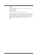
CHAPTER 1 Command Processing 1.1 Command Format 1.2 Status Byte 1.3 Outline of Command Processing 1.4 Command Queuing Function 1.5 UNIT ATTENTION Condition 1.6 Sense Data Hold State 1.7 Command Processing Exceptions 1.8 Data Block Addressing This chapter describes the basic logical specifications of the IDD command processing functions. Note: The IDD operates as the target (TARG) on the SCSI bus.
Command Processing Bit Byte 7 6 5 0 4 3 2 1 0 0 0 0 0 0 0 2 1 0 0 0 0 0 0 0 Operation Code 1 LUN 0 0 2 Logical Block Address (MSB) 3 Logical Block Address 4 Logical Block Address 5 Logical Block Address (LSB) 6 0 0 0 0 0 7 Transfer Data Length (MSB) 8 Transfer Data Length (LSB) 9 Control Byte Figure 1.
1.1 Command Format (1) Operation code Bit 7 6 5 Group Code 4 3 2 1 0 Command Code The leading byte of all CDBs shows the format and type of command to be executed. a. Group code The group code specifies the number of bytes and format of the CDB. The groups of commands shown below are used in the IDD. • Group 0 (“000”):6-byte CDB (Shown in Figure 1.1) • Group 1 (“001”):10-byte CDB (Shown in Figure 1.2) • Group 2 (“010”):10-byte CDB (Shown in Figure 1.
Command Processing Furthermore, this field may be used with a different meaning, or it may not have any meaning at all, depending on the type of command. There are also some commands which allocate 3 or more bytes as the transfer data length field. Detailed specifications of these commands are described in the individual command specifications in Chapter 3. a.
1.1 Command Format Note: It is possible that bits 7 and 6 of the control byte will be used in future product specifications as an inherent control field. It is recommended that zeros be specified in this field. (6) Handling an illegal CDB If there is an error in the contents of a description (specification) in the CDB, or if there is an error in the specifications in parameters transferred from the INIT by CDB specifying, that command ends with a CHECK CONDITION status.
Command Processing 1.2 Status Byte Figure 1.4 shows status byte format and the type of status that the IDD supports. The status byte is one byte of information sent from the TARG to the INIT in the STATUS phase when one command is completed, and notifies the INIT of the results of the command’s execution. The status byte is also sent even in cases when the TARG is in a state which it makes it impossible for it to execute the command when it receives a request for an input/output operation.
1.2 Status Byte (2) CHECK CONDITION status This status is reported in the following cases a) to c). The IDD generates sense data when it reports this status and indicates the detailed cause. The INIT issues a REQUEST SENSE command when it receives this status and should sample sense data. a) If the sense key of the sense data indicates RECOVERED ERROR [=1], the last command, which is the last command, indicates that it ended normally with the error recovery processing executed by the IDD.
Command Processing (6) INTERMEDIATE CONDITION MET Status This status is reported when it is possible to secure the cache memory area necessary to read all the logical data blocks specified in a PRE-FETCH command which specifies a link (in the case of “Immed = 1”), or when reading of all the specified logical data blocks is completed (in the case of “Immed = 0”). The IDD does not support the PRE-FETCH command. Therefore, this status is not reported.
1.3 Outline of Command Processing 6) When execution of the command is completed, the TARG reports the execution results by the status byte in the STATUS phase to the INIT. 7) The TARG reports the TASK COMPLETE message to the INIT in the MESSAGE IN phase and enters the BUS FREE phase. 1.3.2 Command link The command link function is a function which causes the TARG to execute continuous processing of multiple commands. Following shows examples of command link processing.
Command Processing Table 1.
1.3 Outline of Command Processing 1.3.3 Disconnect/reconnect processing When processing is performed by the TARG during the command execution process which does not require operation on the SCSI bus, the TARG can return the SCSI bus to the BUS FREE phase temporarily by disconnect processing and execute command internally. Through this function, the INIT is enabled to process multiple commands on the SCSI bus.
Command Processing Table 1.2 Types of Command and Disconnect Processing Commands with executing disconnect processing. (Note 2) Commands without executing disconnect processing.
1.3 Outline of Command Processing (2) Basic disconnect processing procedure Disconnect processing is executed basically by the following processing procedure. 1) If the IDD judges that it is possible for it to disconnect from the SCSI bus during execution of a command, it sends a DISCONNECT message to the INIT and enters the BUS FREE phase. At this time, if necessary, the IDD sends a message to activate a pointer in the INIT which precedes sending of the DISCONNECT message.
Command Processing Note: In disconnect processing in this case, transfer of all the data accompanying execution of the command is complete and there is actually no necessity for the SAVE DATA POINTER message.
1.3 Outline of Command Processing 3) After the INIT that accepts the IDENTIFY message normally completes the pointer restore operation, it should make the ACK signal for the IDENTIFY message FALSE. If the ATTENTION condition does not exist when the ACK signal becomes FALSE during sending of the IDENTIFY message, the IDD regards the reconnection processing as having been normally completed and begins subsequent processing.
Command Processing The IDD maintains data transfer mode settings between itself and each INIT individually. Therefore, an INIT which uses asynchronous mode transfer and an INIT which uses synchronous mode transfer can both coexist on the same SCSI bus. Also, the parameters for synchronous mode transfers decided by the SYNCHRONOUS DATA TRANSFER REQUEST message can differ for each INIT and an INIT which uses the 8-bit width transfer mode can coexist with an INIT which uses the 16-bit width transfer mode.
1.4 Command Queuing Function When a command is in the queued state, if a RESET condition occurs, or if the IDD receives a TARGET RESET message from any INIT, it clears all the commands in the queue. At this time, the IDD generates on UNIT ATTENTION condition for all the INITs. When an ABORT message is sent from an INIT that has issued a command which is in the queue, if the correct LUN (0) is specified, only the command issued by that INIT is cleared and the other commands in the queue are not effected.
Command Processing 1.4.2 a) When there is an error in the CDB, the IDD responds with a CHECK CONDITION status at the point when that command is fetched from the queue. b) If the IDD is in the not ready state at the point when the queued command is fetched, it responds with a CHECK CONDITION status. c) If a UNIT ATTENTION condition is generated before the queued command is fetched, a CHECK CONDITION status may be replied.
1.5 UNIT ATTENTION Condition The INIT can specify 2 error recovery options by the QErr bit of the control mode parameter (Page A) of the mode select parameters. When “0” is specified in the QErr bit, the IDD enters any one of a number of sense hold states, and when this state is released, it continues to execute the commands in the queue.
Command Processing (1) When power on, RESET or TARGET RESET occurs If the IDD’s power is switched on, the IDD enters the RESET condition or is reset by a TARGET RESET message, this UNIT ATTENTION condition is generated for all the INITs, regardless of whether the disk drive is in the ready state or not.
1.
Command Processing The IDD executes the REQUEST SENSE command normally and sends the sense data which indicate the UNIT ATTENTION condition and are being held to the INIT. At this time, the UNIT ATTENTION condition for that INIT is cleared. 1.5.
1.7 Command Processing Exceptions 1) If a command is issued to the logical unit in the sense data hold state by the INIT which is the object of sense data holding. – – In the case of an untagged command REQUEST SENSE command: The sense data held by the IDD are transferred to the INIT and the sense hold state is released. Other commands: The sense data hold state is released and the command is executed normally if commands issued from the INIT are not queued.
Command Processing 2) The IDD reports a CHECK CONDITION status for a command that generates an overlap. At this time, the sense data generated by the IDD indicates ABORTED COMMAND [=B]/Overlapped commands attempted [=4E-00], or Tagged Overlapped [=4D-nn] (nn: tag No.). Notes: 1.7.
1.7 Command Processing Exceptions • When reading of system information is not completed, or reading failed. Also, if initialization of the disk media (formatting) has not been completed normally, it will be impossible to access data on the disk media. Processing of and response to commands received by the IDD when it is in the not ready state or in the initialization incomplete state are described below.
Command Processing reached the normal rotating speed, or if reading of system information is still in progress, a CHECK CONDITION status is reported as in item (1).
1.7 Command Processing Exceptions Table 1.4 Outline of SCSI Bus Error Recovery Processing Item (2) Type of Error Error Recovery Processing 1 MESSAGE OUT phase parity error 2 COMMAND phase parity error 3 4 DATA OUT phase parity error Received INITIATOR DETECTED ERROR message. 5 6 Received MESSAGE PARITY ERROR message.
Command Processing 1.7.6 Reset processing The INIT can reset the SCSI bus with following. • • • • • RESET condition TARGET RESET message CLEAR TASK SET message ABORT TASK SET message ABORT TASK message The RESET condition resets all the SCSI devices connected on the same SCSI bus. The IDD is initialized to the same state as when its power is switched on by the RESET condition, with the currently executed command as well as all the commands in the queue cleared.
1.7 Command Processing Exceptions Table 1.6 Type of command Reset processing during write Halting process of command execution WRITE WRITE EXTENDED WRITE AND VERIFY SEND DIAGNOSTIC (Write/Read Test) WRITE LONG WRITE SAME Data blocks which are currently being written are processed normally, including the ECC portion, and execution of the command is terminated at the point when that processing is completed. Not all the data transferred from the INIT to the IDD will necessarily be written to the disk media.
Command Processing After this state occurs, the IDD reports the CHECK CONDITION status for all input/output operation requests except the REQUEST SENSE command. The sense data reported at this time indicate HARDWARE ERROR [=4] / Internal target failure [=44-nn]. If this state is reported continuously for input/output operation requests, it is necessary for the INIT to generate a RESET condition or send a TARGET RESET message and attempt to recover from the error state.
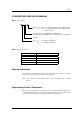
1.8 Data Block Addressing Physical cylinder [System space] Cylinder 0 Track 0 a Cylinder 0 Track 1 a Cell 0 Cylinder 0 Zone 0 Track (m-1) a Cell 1 [User space] Track 0 Alternate cylinder (b-1) (b cylinders) Zone 1 Cylinder (a-1) Zone (x-1) Alternate cylinder (c cylinders) Last cylinder (d-1) (Last cylinder) MAP3147 MAP3735 MAS3367 MAS3735 73 a 14 TBD b 1 TBD c TBD 1044 d 48970 m 8 x TBD TBD 49040 49166 TBD TBD 4 2 TBD 18 Figure 1.
Command Processing 1.8.2 Logical block addressing The IDD uses logical data block addressing which is not dependent on the disk drive’s physical structure as the method of data access on the disk medium. The IDD makes correspondence between each physical sector and each logical data clock address during formatting. Access to the data on the disk medium is performed in logical data block units and the INIT specifies the logical data block address that is its object during access.
CHAPTER 2 Data Buffer Management 2.1 Data Buffer 2.2 Look-Ahead Cache Feature 2.3 Write Cache In this chapter, the configuration of the data buffer with which the IDD is equipped, its operation and the operation of the cache feature are described. 2.1 Data Buffer 2.1.1 Data buffer configuration and basic operation The IDD is equipped with a data buffer, which makes it possible to efficiently execute data transfer operations between INIT (initiator) and a disk drive.
Data Buffer Management Segment Segment 7 Segment 6 Segment 5 Segment 4 Segment 3 Segment 2 Segment 1 Segment 0 Disk Media Valid Data INIT Write→ Write→ ←Read ←Read Figure 2.1 Data buffer configuration (in the case of 8 cache segments) The basic functions and operations of the data buffer in a read operation and a write operation are shown below. (1) Read operation Data read from the disk media are temporarily stored in the data buffer.
2.1 Data Buffer 6) When transfer of all the specified data is completed, the IDD reports the status and terminates the command. Note: In order to avoid frequent repetition of the disconnect/reconnect processing after data transfer starts on the SCSI bus, and avoid the occurrence of data overruns, it is necessary to set the buffer full ratio (see Section 2.1.
Data Buffer Management 3) If the data transfer rate of the INIT (SCSI bus) is lower than the data transfer rate of the disk drive, since the data pre-fetch of data that are to be written to that data block is not completed, it may not be possible to write the data continuously to the disk (data underrun). In this case, the IDD waits one disk revolution while continuing to pre-fetch data from the INIT, then repositions the block that caused the data underrun and continues the writing of data to the disk.
2.1 Data Buffer 2.1.2 Operation mode setting (1) MODE SELECT parameter In order to make it possible to control from the INIT the reconnection processing start timing for executing data transfers with the SCSI bus in read and write operations, the IDD is provided with the MODE SELECT parameter (Disconnect/Reconnect Parameter: Page code = 2) shown in Figure 2.4. The user can set the optimum operating state in the system environment as necessary.
Data Buffer Management b. Buffer empty ratio This parameter specifies the timing for the IDD to start reconnection when it is requested by the INIT to transfer data in the WRITE, WRITE EXTENDED or WRITE AND VERIFY command. In a write operation, after the IDD receives a command, the IDD begins transferring data (data pre-fetch) while locating the position of the target data blocks on the disk media in parallel.
2.
Data Buffer Management b) If any of the following commands is issued, all the data which are objects of caching are disabled.
2.2 Look-Ahead Cache Feature 2.2.2 Caching parameters The IDD supports the MODE SELECT parameters (caching parameters: page code = 8) shown in Figure 2.5 for controlling the cache feature. See Section 4.1 concerning details of the MODE SELECT parameters.
Data Buffer Management 2.2.3 Look-Ahead operation, Look-Ahead volume 1) Excluding the conditions in 3) and 4) for the amount of data specified as the minimum pre-fetch volume, data are read for look-ahead irrespective of track boundaries or cylinder boundaries. Commands which are already in the queue or commands which are newly received while a lookahead operation is in progress, are executed after the look-ahead operation is completed.
2.3 Write Cache 2.3 Write Cache The IDD is equipped with a write cache function in order to reduce the INIT's command processing time. If that operation is permitted by the MODE SELECT command (caching parameters: Page code = 8, WCE bit), at the point when the IDD completes the transfer of all data specified in the WRITE or WRITE EXTENDED command, it reports the GOOD status and terminates the command.
This page is intentionally left blank.
CHAPTER 3 Command Specifications 3.1 Control/Sense Commands 3.2 Data Access Commands 3.3 Format Commands 3.4 Maintenance, Diagnostic Commands This chapter describes detailed specifications of the SCSI commands which the IDD is equipped with and how to use them. 3.1 Control/Sense Commands 3.1.
Command Specifications 3.1.2 INQUIRY (12) Bit Byte 7 6 5 4 0 3 2 1 0 0 0 CmdDt EVPD 0 0 0 0 0 Link X‘12’ 1 LUN 0 2 Page Code/Operation Cpde 3 0 0 0 4 0 0 Transfer Byte Length 5 0 0 0 0 0 This command transfers the information showing the IDD's characteristics (INQUIRY data) to the application client. This command is executed immediately without queuing in a system which issues only commands with no tags or links.
3.1 Control/Sense Commands (1) EVPD (Enable Vital Product Data) a) If the specification in this bits is zero, the IDD transfers the standard INQUIRY data or the command supported data, mentioned later, to the application client. b) If the specification in this bits is one, product information called VPD (vital product data) is transferred to the application client.
Command Specifications Bit 7 6 5 4 3 2 1 SCSI mode 0 Byte 0 Qualifier (0, 0, 0) or (0, 1, 1) RMB 0 0 0 RMB 0 0 0 1 2 3 AENC TrmIOP 0 0 0 1 AERC Obsolete 0 0 4 0 1 0 0 SCCS 0 0 0 0 (Reserved) 5 6 7 ~ ~ 0 0 BQue EncServ 0 0 0 0 RelAdr WBus32 0 0 ~ RelAdr Obsolete ~ 0 0 8 9 ~ ~ ~ ~ 15 16 17 31 32 33 34 35 36 37 Device Type Code (0, 0, 0, 0, 0) or (1, 1, 1, 1, 1) Reserved 0 0 0 0 0 Device Type Code 0 0 0 0 0 Version X’ 01’ (SCSI-1) X’ 02’ (SCSI-2) X’ 03’ (SPC) Response Data Format 0 0
3.1 Control/Sense Commands a. Qualifier field (0,0,0): The specified logical unit shows the type of input/output device shown in the "Device Type Code" field. Even if this code is reported, it does not mean that that logical unit is in the ready state. (0,0,1): The specified logical unit shows the type of input/output device shown in the "Device Type Code" field, but it shows that an actual input/output device is not connected to that logical unit. The IDD does not report this code.
Command Specifications g. Supported functions The bit positions shown below are valid only when the CHANGE DEFINITION command is set so that the SCSI-2 or SCSI-3 mode INQUIRY data are transferred, and the functions which the IDD supports are shown in the bit correspondence. "1" indicates that that function is supported and "0" indicates that that function is not supported.
3.
Command Specifications k. Device Serial Number field The value following byte 4 of the device serial number in the VPD information is indicated in this field. Higher order digits which do not contain valid numbers are filled with ASCII code spaces (X '20'). l. Clocking field This field indicates the code which shows the clocking method. The definition of the code is as shown below.
3.1 Control/Sense Commands (6) Command Support Data Figure 3.2 shows the format and contents of the command support data transferred to the INIT by this command if "0" is specified in the "EVPD" bit and "1" is specified in the "CmdDt" bit. Bit 7 6 5 4 3 2 1 0 Byte 0 Qualifier 1 0 Device Type Code 0 0 0 0 Support 2 Version 3 X'00' (Reserved) 4 X'00' (Reserved) 5 CDB Size (m-5) 6 ~ ~ CDB Usage Data ~ m Figure 3.2 Command support data a.
Command Specifications media. When this is the case, a subsequent request for command support data may be successful. c. CDB size This field contains the number of bytes in the CDB for the operation code being queried, and the size of the "CDB Usage Data" field in the return data. d. CDB usage data This field contains information about the CDB for the operation code being queried. The first byte of the "CDB usage data" contains the operation code for the operation being queried.
3.1 Control/Sense Commands Bit 7 Byte 0 6 5 4 3 Qualifier 2 1 0 Device Type Code 1 X‘00’ (Page Code) 2 X‘00’ 3 X‘03’ (Page Length) 4 X‘00’ (Page Code List) 5 X‘80’ (Device Serial No.) 6 X‘C0’ (Operation Mode) Figure 3.3 VPD information: VPD identifier list The values indicated in the "Qualifier" and "Device Type Code" fields in byte 0 are the same as those in the previously mentioned standard INQUIRY data.
Command Specifications The values indicated in the "Qualifier" and "Device Type Code" fields in byte 0 are the same as those in the previously mentioned standard INQUIRY data. The "Page code" field in byte 1 indicates the page code (X '80') of this VPD information itself. Also, the "Page length" field in byte 3 indicates the length (byte length) after byte 4.
3.1 Control/Sense Commands 3.1.3 READ CAPACITY (25) Bit Byte 7 6 5 0 4 3 2 1 0 0 0 0 0 0 X‘25’ 1 LUN 2 Logical Block Address (MSB) 3 Logical Block Address 4 Logical Block Address 5 Logical Block Address (LSB) 6 0 0 0 0 0 0 0 0 7 0 0 0 0 0 0 0 0 8 0 0 0 0 0 0 0 PMI 9 0 0 0 0 0 0 0 Link This command transfers information related to the disk drive's capacity and the data block size to the INIT.
Command Specifications Bit 7 Byte 6 5 2 Logical Block Address (MSB) 1 Logical Block Address 2 Logical Block Address 3 Logical Block Address (LSB) 4 Block Length (MSB) 5 Block Length 6 Block Length 7 Block Length (LSB) 1 0 READ CAPACITY data CHANGE DEFINITION (40) Bit Byte 3 0 Figure 3.6 3.1.
3.1 Control/Sense Commands This command specifies a different SCSI level in the "SCSI level" field in SCB byte 3. The SCSI level is indicated by 1 byte of code as shown in the following table. If a code other than the following codes is specified, the command is terminated by a CHECK CONDITION status (ILLEGAL REQUEST [=5] / Invalid field in CDB [=24-00] and the SCSI level and operation mode are not changed.
Command Specifications Bit Byte 7 6 5 4 3 2 0 X‘00’ 1 X‘00’ 2 X‘00’ 3 X‘04’ (Parameter Length) 4 0 0 0 5 PHSCRC AGD ACE 0 Header WDTR UNTAIN SDTR 0 1 0 0 RSRTY 0 RTD 6 X‘xx’ (Spindle Motor Start Delay Time) 7 X‘00’ (Reserved) Parameter List The operation mode parameter is configured from a 4-byte parameter list following a 4-byte header. (1) Header a) Bytes 0 to 2 X '00' must be specified in this field.
3.1 Control/Sense Commands * Set at shipping time b) UNTATN (UNIT ATTENTION report mode) This specifies the response method to commands received from the INIT when the IDD is holding a UNIT ATTENTION condition: "1"* (Report): The IDD reports a CHECK CONDITION status (Standard SCSI specification) in response to commands other than INQUIRY and REQUEST SENSE. "0" (No Report): The IDD terminates all commands that are received normally.
Command Specifications * Set at shipping time The IDD ignores this specification and operates with the settings specified at shipping. f) ACE (AIP checking enabled) This specifies whether or not it is permitted to check AIP (Asynchronous Information Protection). "1" (Permitted): Permitting check "0"*(Prohibited): Prohibiting check * Set at shipping time The IDD ignores this specification and operates with the settings specified at shipping.
3.1 Control/Sense Commands 3.1.5 MODE SELECT (15) Bit Byte 7 6 5 4 3 2 1 0 PF 0 0 0 SP 0 X‘15’ 1 LUN 2 0 0 0 0 0 0 0 0 3 0 0 0 0 0 0 0 0 0 0 Link 4 Parameter List Length 5 0 0 0 0 0 This command performs setting and changing of each type of parameter related to disk drive physical attributes, data format, timing of SCSI bus disconnect/reconnect processing and error recovery procedures, etc.
Command Specifications If a "Header," "Block Descriptor" or any "Page Descriptor" cannot be transferred with all the defined length because the total defined length of the MODE SELECT parameters actually transferred from the INIT do not match the value specified in the "Parameter List Length" field, or if the total of the MODE SELECT parameter's defined length transferred from the INIT exceeds the value specified in the "Parameter list length" field, this command is terminated with a CHECK CONDITION status
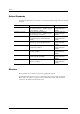
3.1 Control/Sense Commands Current values MODE SELECT [Command to all INITs] Pages: 1, 2, 7, 8, A, C, 1C, 21 Power-on RESET condition Save values TARGET RESET message [Command to all INITs] MODE SELECT (SP=1) Pages: 1, 2, 7, 8, A, 1C, 21 Power-on [Command to all INITs] [Command to all INITs] Block descriptor Pages: 3, 4 FORMAT UNIT Power-on RESET condition TARGET RESET message Default values [Command to all INITs] Pages: 1, 2, 7, 8, A, C, 1C, 21 Figure 3.
Command Specifications If the IDD performs rounding processing ("rounding up" or "rounding down") of parameter values specified by the INIT, in some cases a "CHECK CONDITION" status (RECOVERED ERROR [=1] / Rounded parameter [37-00]) is reported, and in some cases it is not reported. Whether or not a "CHECK CONDITION" status is reported is determined by the type of "rounding up" or "rounding down" and the conditions.
3.1 Control/Sense Commands Page Descriptor Bit Byte 0 Page Header 7 6 0 0 1 5 4 3 2 1 0 Page Code Page Length 2 ~ ~ ~ ~ Parameter Field ~ ~ n Figure 3.8 MODE SELECT command (Group 0) parameter configuration a. Header • Media type X '00' (default type) must be specified in this field. • Byte 2 Bits 7 and 4 of this field have meaning only in the header transferred to the INIT by the MODE SENSE and MODE SENSE EXTENDED commands.
Command Specifications If only the "Block descriptor" in this command is changed, the IDD changes the values in the "Sector count/track," Data byte length/physical sector," "Track skew factor" and "Cylinder skew factor," as well as the "Cylinder count" value in the drive parameters (Page 4) in accordance with the contents specified in the "Block descriptor," and uses the "Current" values as is for the other parameters.
3.1 Control/Sense Commands c. Page descriptor The "Page descriptor" is configured from a 2-byte page header followed by a parameter field and each parameter function attribute is classified in a unit called a "Page." The individual "Page descriptors" in the MODE SELECT and MODE SELECT EXTENDED commands may be specified independently by the INIT and multiple "Page descriptors" may be specified continuously in the desired sequence. • Page code This field specifies a code (Page No.
Command Specifications 2. After changing anything in the "Block descriptor," "Format parameters (Page 3)" or "Drive parameters (Page 4)," with the MODE SELECT or MODE SELECT EXTENDED command, it is impossible to execute a command to access the data on the disk media until execution of the FORMAT UNIT command is completed, and a CHECK CONDITION status (MEDIUM ERROR [=3] / Medium format corrupted [=31-00]) is reported for all such commands.
3.1 Control/Sense Commands Figure 3.9 shows the configuration of the parameter list (MODE SELECT parameters) transferred by this command from the INIT. Compared to the 4-byte header in the Group 0 MODE SELECT command, it is necessary for an 8-byte header to be transferred in this command. The contents of each field in the header except that the byte positions differ, are the same as in the case of the Group 0 MODE SELECT command.
Command Specifications Page Descriptor Bit Byte 0 Page Header 7 6 0 0 5 4 3 2 1 0 Page Code 1 Page Length 2 ~ ~ ~ ~ ~ ~ Parameter Field n Figure 3.9 3.1.
3.
Command Specifications Table 3.1 PC MODE SENSE Data Type Specifications Type of Parameter Transferred to the INIT 00 Current Values: Reports each "Current" parameter value. The "Current" values are either of the following values. • Values specified by a MODE SELECT or MODE SELECT EXTENDED command which is finally normally terminated.
3.
Command Specifications (1) Header a. Sense data length This field indicates the length (number of bytes) of the parameter list (MODE SENSE data) which it is possible to transfer to the INIT by this command. The length of the "Sense data length" field itself is not included in this value.
3.1 Control/Sense Commands Furthermore, when this command specifies to transfer the "Default" value and "Variable" value, the value shown in this field is X '00000000' (which means the maximum number of logical data blocks that it is possible to rank in the "User Space"). b. Data block length This field indicates the length (byte length) of 1 logical data block on the disk media.
Command Specifications 3.1.
3.1 Control/Sense Commands Block Descriptor Bit 7 Byte 6 5 4 3 2 0 Data Block Count (MSB) 1 Data Block Count 2 Data Block Count 3 Data Block Count (LSB) 4 X‘00’ 5 Data Block Length (MSB) 6 Data Block Length 7 Data Block Length (LSB) 1 0 Page Descriptor Bit 7 6 PS 0 Byte 0 5 4 3 2 1 0 Page Code 1 Page Length 2 ~ ~ ~ ~ Parameter Field n Figure 3.11 MODE SENSE EXTENDED command (Group 2) parameter configuration 3.1.
Command Specifications This command moves the read/write heads of the disk drive to the initial position. A data block with the logical block address of zero exists at the initial position (cylinder 0 / track 0). Initialization of the disk drive's positioning control system and automatic adjustment are also performed by this command. 3.1.
3.1 Control/Sense Commands Depending on the value specified in the "Immed (immediate)" bit, bit 0 of CDB byte 1, the timing of completion (status byte report) of this command differs as shown below. a. In the case of the start specification ("Start" bit = "1") • When the "Immed" bit is "1," simply by instructing starting of the spindle motor, a GOOD status is reported without waiting until the disk drive is in the Ready state, and command execution is completed.
Command Specifications Together with the RELEASE command, this command controls exclusive access to the logical unit (IDD) under a multi-initiator environment. The IDD is reserved by this command for the INIT which issued this command or for some other SCSI device specified in the CDB. The INIT which issues this command must notify the IDD of its own SCSI ID when the SELECTION phase is executed..
3.1 Control/Sense Commands (3) Changing the reserve conditions (Superseding Reserve) The INIT which has the reserve right for an IDD (the INIT which has issued this command in the past and has established the IDD reserve state) can change the IDD's reserve conditions by issuing a another RESERVE command (Superseding Reserve).
Command Specifications • INIT #A can issue INQUIRY, REQUEST SENSE, RELEASE and RESERVE commands to TARG #0, but other commands are rejected with a RESERVATION CONFLICT status. A RELEASE or RELEASE EXTENDED command issued by INIT #A releases TARG #0's reserved state. Also, a RESERVE or RESERVE EXTENDED command changes the reserve state of TARG #0. • Commands issued by INIT #B to TARG #0 are rejected with a RESERVATION CONFLICT status, except the INQUIRY, REQUEST SENSE and RELEASE commands.
3.1 Control/Sense Commands 3.1.13 RELEASE (17) Bit Byte 7 6 5 4 0 3 2 1 0 X‘17’ 1 LUN 3rd Pty 3rd Pty Dev ID 0 2 × × × × × × × × 3 0 0 0 0 0 0 0 0 4 0 0 0 0 0 0 0 0 5 0 0 0 0 0 0 0 Link This command releases the reserve state of an IDD in relation to the INIT that issued this command.
Command Specifications 3.1.14 RELEASE EXTENDED (57) Bit Byte 7 6 5 4 3 2 1 0 3rd Pty 0 0 0 0 × × × × × 0 X‘57’ 1 LUN × 2 × × 3 Third Party Devices ID 4 0 0 0 0 0 0 0 0 5 0 0 0 0 0 0 0 0 6 0 0 0 0 0 0 0 0 7 × × × × × × × × 8 × × × × × × × × 9 0 0 0 0 0 0 0 Link This command releases the reserve state of an IDD in relation to the INIT which issued this command.
3.1 Control/Sense Commands The length of the sense data in the IDD is 48 bytes. The "Transfer byte length" field in the CDB indicates the number of bytes of sense data which can be received by the INIT. The IDD transfers sense data to the INIT by either of the following two methods, depending on the specification in the CHANGE DEFINITION command (SCSI level). Furthermore, see Section 3.1.4 (SCSI Level) concerning the CHANGE DEFINITION command.
Command Specifications • • • Sense data cannot be sent due to a hardware error in the IDD An unrecoverable error is detected on the SCSI bus. A state appropriate to an overlapping command exception condition (see Section 1.7.1). In cases other than the above, the sense data currently being held, or, when there are no sense data being held, the sense data which indicate the state if an error occurred during execution of this command, are sent to the INIT and it is terminated with a GOOD status.
3.1 Control/Sense Commands Value Description 00b Current threshold values 01b Current cumulative values 10b Default threshold values 11b Default cumulative values The "PC" bits are ignored by the drive. The drive assumes that current cumulative parameters are selected. The "Parameter List Length" field specifies the length in bytes of the parameter list that is located in the Data-Out Buffer.
Command Specifications (1) Page code This field indentifies which log page is being transferred. The log pages that can be transferred by this command are shown below.
3.1 Control/Sense Commands (1) Paramter code This field identifies the log paramter being transferred for that log page. (2) Byte 2 a) DU (Disable Update) "1" : The IDD does not update the log parameter value except in responce to a LOG SELECT command that specifies a new value for the parameter. "0" : The IDD updates the log parameter value to reflect all events that are noted by that parameter.
Command Specifications (4) Parameter value This field indicates actual "threshold value" or "cumulative value". The size of this field differs in each log parameter. 3.1.
3.
Command Specifications The PERSISTENT RESERVE IN command obtains information about the reservation requirements and reservation keys that are valid in the target range. This command is used in combination with the PERSISTENT RESERVE OUT command (See Section 3.1.19). When this command is received, if the reservation in the target is enabled by the RESERVE command, the command is rejected and is returned with the RESERVATION CONFLICT status.
3.1 Control/Sense Commands 3.1.18.1.2 READ RESERVATIONS In the READ RESERVATION service action, the drive transfers the following information to the initiator as a parameter data list. • • • • Current generation value (See Section 3.1.18.
Command Specifications This counter value is not incremented in the following cases: When the PERSISTENT RESERVE IN command is executed When the RESERVE or RELEASE service action of the PERSISTENT RESERVE OUT command is executed If the PERSISTENT RESERVE OUT command cannot be executed because of an error or a reservation conflict. The "Generation" field is reset to zero in Power-On reset processing, regardless of the APTPL bit specification.
3.1 Control/Sense Commands The "Additional Length" field contains a count of the number of bytes to follow in the "Reservation Descriptors" field. If the specified allocation length in the CDB of the PERSISTENT RESERVE IN command is not sufficient for containing the entire parameter list, a portion of the parameter list from byte 0 to the specified allocation length is transferred to the initiator.
Command Specifications Code Name Description 0h Logical Unit Persistent reservation applies to an entire logical unit 1h Reserved Reserved 2h Element (not supported) Persistent reservation applies to the specified element Reserved Reserved 3h-Fh 3.1.18.3.1.1 Logical Unit scope The "Scope" field value of the Logical Unit indicates that persistent reservations apply to the entire Logical Unit.
3.1 Control/Sense Commands Table 3.2 Persistent reservation type codes Code Name 0h Reserved 1h Write Exclusive 2h Reserved 3h Exclusive Access Description Reads Shared: Any initiator can execute read commands Writes Exclusive: Except by an initiator holding a persistent reservation, a write command executed by any initiator causes a reservation conflict.
Command Specifications 3.1.19 PERSISTENT RESERVE OUT (5E) Bit 7 6 5 4 3 2 1 0 Byte 0 1 X'5E' 0 0 2 0 Service Action Scope Type 3 0 0 0 0 0 0 0 0 4 0 0 0 0 0 0 0 0 5 0 0 0 0 0 0 0 0 6 0 0 0 0 0 0 0 0 7 (MSB) Parameter List Length (18h) 8 9 (LSB) Control The PERSISTENT RESERVE OUT command reserves a logical unit for exclusive or shared use by a particular initiator. This command is used in combination with the PERSISTENT RESERVE IN command.
3.1 Control/Sense Commands The RESERVE, PREEMPT, and PREEMPT AND ABORT service actions of this command determine whether any conflict of Scope or Type specifications occurs between two reservation requirements: the new one provided by this command, and the other one already being held on the drive. If the reservation requirements conflict, the command is rejected and returned with the RESERVATION CONFLICT status. In this case, RESERVE, PREEMPT, and CLEAR processing is not executed.
Command Specifications Table 3.3 PERSISTENT RESERVE OUT command service action codes Code Name Description 00h REGISTER Registers a reservation key on the drive. 01h RESERVE Generates a persistent reservation for the specified Scope and Type using the reservation key. 02h RELEASE Releases the persistent reservation. 03h CLEAR Clears all reservation keys and persistent reservations. 04h PREEMPT Dispossesses a persistent reservation from another initiator.
3.1 Control/Sense Commands For the "Reservation Key" field, an 8-byte key code provided by the application client is set in order to enable the drive to identify the initiator that is the source of the PERSISTENT RESERVE OUT command. The drive can then verify that the "Reservation Key" field in the PERSISTENT RESERVE OUT command matches the registered reservation key for the initiator that issues the command.
Command Specifications Table 3.
3.1 Control/Sense Commands This command requests that the peripheral device logical unit inventory be sent to the application client. This command normally operate under the reserve condition (RESERVE or PERSISTENT RESERVE). The "Allocation Length" should be at least 16 bytes. If the "Allocation Length" is less than 16 bytes, the IDD reports the CHECK CONDITION status (ILLEGAL REQUEST [=5] / Invalid Field in CDB [=24-00]).
Command Specifications 3.1.
3.1 Control/Sense Commands The "Identifier Length" field specifies the length in bytes of the "Identifier" field. If the "Allocation Length" field in the CDB is too small to transfer all of the identifier, the length shall not be adjusted to reflect the truncation. The identifier length shall initially equal zero, and shall be changed only by a successful SET DEVICE IDENTIFIER command. The "Identifier" field shall contain a vendor specific value.
Command Specifications The "Allocation Length" field specifies the length in bytes of the Identifier that shall be transferred from the application client to the device server. The maximum value for this field shall be 512 bytes. A parameter list length of zero indicates that no data shall be transferred, and that subsequent REPORT DEVICE IDENTIFIER commands shall return an Identifier length of zero.
3.2 Data Access Commands 3.2 Data Access Commands 3.2.1 READ (08) Bit 7 Byte 6 5 4 0 3 2 1 0 X‘08’ 1 LUN Logical Block Address (MSB) 2 Logical Block Address 3 Logical Block Address (LSB) 4 Transfer Block Count 5 0 0 0 0 0 0 0 Link This command reads the number of blocks of data in continuous logical data blocks specified in the "Transfer block count" field with the logical data block on the disk media specified in the "Logical block address" field in the CDB as the top.
Command Specifications 3.2.
3.2 Data Access Commands 3.2.
Command Specifications Note: Even when there is an error in the specification in the CDB, or when a write operation to the disk media cannot be executed normally due to various other causes, the transfer of data (data is prefetched to the data buffer) from the INIT to the IDD may be executed. In this case, the length of data transferred from the INIT to the IDD is undefined. Also, all the data transferred to the IDD will not necessarily be actually written to the disk media.
3.2 Data Access Commands When this bit is "1", it indicated that the IDD shall access the media in performing the command prior to returning GOOD status. WRITE commands shall not return GOOD status until the logical blocks have actually been written on the media (i.e., the data is not write cached). 3.2.
Command Specifications processing is not prohibited, even if a correctable data check is detected during the verify check, it is regarded as if the verify check succeeded. 3.2.
3.2 Data Access Commands 3.2.7 SEEK (0B) Bit Byte 7 6 5 4 0 3 2 1 0 X‘0B’ 1 LUN Logical Block Address (MSB) 2 Logical Block Address 3 Logical Block Address (LSB) 4 0 0 0 0 0 0 0 0 5 0 0 0 0 0 0 0 Link This command executes a seek operation of the cylinder/track where the logical data block specified in the "Logical block address" field in the CDB exists. When disconnect processing is permitted, the IDD performs disconnect processing after receiving the CDB.
Command Specifications This command executes a seek operation of the cylinder/track where the logical data block specified in the "Logical block address" field in the CDB exists. The functions and operation of this command are the same as those of the Group 0 SEEK command (Section 3.2.7), except that it is possible to specify 4-byte logical block addresses. 3.2.
3.2 Data Access Commands Also, the size of the range where access is permitted, specified in this command in the "Block count" field in the CDB, specifies the number of logical data blocks from that starting point. However, when zero is specified in the "Block count" field, access to the final logical data block of the specified data space (User Space or CE Space), with the logical data block specified in the "Logical block address" field as the starting point, is permitted. Figure 3.
Command Specifications Notes: 1. Commands which come under restrictions in read operations or write operations when "1" is specified in the "RdInh" (read inhibit) or "WrInh" (write inhibit) flag are as follows. “RdInh” • READ • READ EXTENDED (*) • READ LONG • VERIFY (*) • WRITE AND VERIFY (*) • PRE-FETCH • FORMAT UNIT • WRITE EXTENDED (*) • REASSIGN BLOCKS • WRITE LONG • WRITE • WRITE SAME • WRITE AND VERIFY (*) When zero is specified in the processing block count, that command is not executed.
3.3 Format Commands The values specified in the "Logical block address" field and "Block count" field in the CDB are disregarded and if any unwritten data exist in the data buffer, writing of all those data to the disk media is performed. If bit 1 of CDB byte 1, the "Immed (immediate) bit, is "1," a GOOD status is reported immediately at the point when the legality of the CDB is confirmed and the command is terminated.
Command Specifications (1) Defect list In order to register or specify the positions of defects on the disk media in connection with defect management processing that can be specified from the INIT, the following types of “Defect List” are defined. a. P List: primary defect list Defect position information (permanent defects) is registered in this list at the time the disk drive is shipped from the factory. The P List registers areas on the disk media which clearly cannot be accessed from the INIT.
3.3 Format Commands (2) Specifying the initialization method The INIT can specify the method of defect processing executed by this command in the “FmtData (format data)” bit and “CmpLst (complete list)” bit of CDB byte 1 and the “Defect List Format” field. When “1” is specified in the “FmtData (format data) bit, it indicates that the format parameters (header and defect list), described later, are transferred from the INIT when this command is executed.
Command Specifications (3) Format parameters Figure 3.13 shows the data format of the Format parameter transferred from the INIT when “1” is specified in the “FmtData (format data)” bit of the CDB.
3.3 Format Commands a. Header The top of the format parameter transferred from the INIT is a 4-byte header. The INIT can specify the method used for defect processing that is executed by this command by control flags within the header. • • FOV (format option valid) 0: Indicates that the INIT does not specially specify concerning the functions specified by the control flags in bits 6 to 4 of byte 1 (see following “DPRY” to “STPF”.).
Command Specifications • Immed (Immediate) “1” : If “1” is specified in the Immed (immediate) bit, at the point when the CDB’s legality is confirmed, or at the point when transfer of the defect list is completed, a “GOOD” status is reported. “0” : If “0” is specified in the Immed (immediate) bit, the specified operation is executed and the status byte is reported at the point when that operation is completed, then the command is terminated.
3.3 Format Commands Note: In order to specify an entire track as defective, X ‘FFFFFFFF’ must be specified as the byte distance from the index to the defect position. Bit Byte 7 6 5 4 3 0 Cylinder No. (MSB) 1 Cylinder No. 2 Cylinder No. (LSB) 3 Head No. 2 1 4 Byte distance from index to defect position (MSB) 5 Byte distance from index to defect position 6 Byte distance from index to defect position 7 Byte distance from index to defect position (LSB) 0 Figure 3.
Command Specifications Bit Byte 7 6 5 4 3 0 Cylinder No. (MSB) 1 Cylinder No. 2 Cylinder No. (LSB) 3 Head No. 2 1 4 Physical sector No. of defective block (MSB) 5 Physical sector No. of defective block 6 Physical sector No. of defective block 7 Physical sector No. of defective block (LSB) 0 Figure 3.
3.3 Format Commands boundaries (User Space), and is recorded as the G List, but formatting processing is executed only for the User Space in the range specified in the “Block descriptor” and “Format parameters” (Page 3), and the “Drive parameters” (Page 4) of the MODE SELECT parameter. 3.
Command Specifications Table 3.
3.3 Format Commands Table 3.5 FORMAT UNIT command defect processing (3 of 3) Note 1) ddd: Note 2) The D List is not transferred from the INIT. Note 3) If the data block length is changed and the disk media is initialized, the INIT cannot specify a combination defect processing method. Note 4) When this combination of defect processing methods is specified, the IDD performs verification of the data blocks after initialization and creates the C List.
Command Specifications Note: Copying of the contents of data in the logical data blocks specified in the “Defect data” list to alternate blocks allocated by this command is attempted, but in some cases, copying cannot be done. Confirmation of the contents of the data in allocated alternate blocks, saving of data before issuing this command and restoring of data after this command is executed are the responsibility of the INIT.
3.3 Format Commands The logical block address of defective data blocks is described in 4-byte format in the defect descriptor. When multiple defect descriptors are specified, it is best for the INIT to describe defect descriptors in the ascending order of the logical data block addresses.
Command Specifications 1. Delete the defect descriptors which precede the defect descriptor that specifies the logical block address displayed in the “Command inherent information” field of the sense data from the defect descriptor list specified in this command, and leave that defect descriptor in the list. Defect Descriptor List XXXX Logical block address that indicates the “Command inherent information” field of the sense data. Delete 2.
3.3 Format Commands PList GList Defect Data Type 1 1 P List and G List 1 0 P List only 0 1 G List only 0 0 4-byte header information only (described in this section) Defect List Format Defect Data Format 0 0 0 Block Address Format 1 0 0 Byte Distance from the Index Format 1 0 1 Physical Sector Address Format The “Transfer byte length” field in the CDB specifies the defect data length (number of bytes) that can be received by the INIT.
Command Specifications b. G List (grown list) bit When this bit is “1,” it indicates that G List defect data are included in the defect descriptor list that is actually transferred to the INIT. When it is “0,” it indicates that the G List defect data are not included. See 3) of item (2).) c. Defect list format This field indicates the description format of the defect descriptor list that is actually transferred to the INIT.
3.3 Format Commands • Defect List Length field: The total number of bytes described in the “Defect List Format” specifying defect data included in the P List and G List. 3. Even if defect data of the type specified in the CDB do not exist in the defect list (P List or G List) (if the defect list is empty), “1” is displayed in the “PList” bit and the “GList” bit in the header transferred to the INIT corresponding to the specification in the CDB. 4.
Command Specifications • 7. When data are in the “Byte Distance from the Index Format,” when the P List is reported, multiple defect position information may be reported for a single sector, or 2 defective sectors may be reported as a single item of defect position information due to defects which extend across sector boundaries. In defect data in the block address format, all the physical defect position information on the disk media cannot be described universally.
3.4 Maintenance, Diagnostic Commands Type of Self-diagnosis Test UnotOfl = “0” UnitOfl = “1” × × 1) Controller Function Test 2) Disk Drive Seek Test × 3) Disk Media (CE Space) Write/Read/Data Comparison Test × ×: Execution Object When the IDD completes all the specified self-diagnosis tests normally, it reports a GOOD status.
Command Specifications Note: When “1” is specified in the “SelfTest (self test)” bit in this command, the command execution results are reported by the status byte and the sense data. Therefore, even if the RECEIVE DIAGNOSTIC RESULTS command is executed after this command, the self-diagnosis test execution results are not reported as response data. Remark: The error recovery control flag is valid only for PER.
3.4 Maintenance, Diagnostic Commands 3. When a command other than the RECEIVE DIAGNOSTIC RESULTS command is linked to this command, the execution results (response data) may no longer be secure. Bit 7 Byte 6 5 0 3 2 1 0 0 0 0 Page Code 1 Header 4 0 0 0 0 0 2 Page Parameter Length (MSB) 3 Page Parameter Length (LSB) 4 Page Parameter ~ ~ ~ ~ ~ ~ Parameter n Figure 3.
Command Specifications This parameter page specifies transfer of the “Page code” list of the parameter page supported by the IDD in the SEND DIAGNOSTIC command and the RECEIVE DIAGNOSTIC RESULTS command to the INIT. Figure 3.19 shows the format of this parameter page. The page code list supported by the IDD is transferred to the INIT by the RECEIVE DIAGNOSTIC RESULTS command which is issued following the SEND DIAGNOSTIC command that specifies this parameter page (shown in Section 3.4.
3.4 Maintenance, Diagnostic Commands The “Address Format Before Conversion” field shows the format of the address information specified in bytes 6 to 13. The IDD converts that address information to the expression format specified in the “Address Format After Conversion” field. the following codes can be specified as the “Address Format.
Command Specifications SELF-TEST Code Description 0,0,0 Refer to clause (2), Parameter Specification. 0,0,1 The device server shall start its short self-test routine in the background mode. 0,1,0 The device server shall start its extended self-test routine in the background mode. 0,1,1 Reserved 1,0,0 Abort the current self-test running in background mode. This value is only valid if a previous this command specified a Background self-test function and that function has not completed.
3.4 Maintenance, Diagnostic Commands Notes: Exercise caution in the following points when using this command. 1. In order to avoid damage to the results of SEND DIAGNOSTIC command execution (response data) from a command issued by another INIT during the interval until this command is issued, either this command should be linked to the SEND DIAGNOSTIC command when it is issued or the SEND DIAGNOSTIC command and this command should be executed after the IDD is reserved. 2.
Command Specifications • Page parameter length This field shows the byte length of the page parameter after byte 4. • Page parameter Data which show the execution results of the operation specified by the SEND DIAGNOSTIC command are reported in this field. (1) Page code list This response data reports the “Page code” list of the parameter page supported by the IDD in the SEND DIAGNOSTIC command and the RECEIVE DIAGNOSTIC RESULTS command after byte 4.
3.4 Maintenance, Diagnostic Commands Bit 7 Byte 6 5 0 4 X ‘40’ 1 0 0 3 2 1 0 0 0 0 (Page Code) 0 0 0 2 X ‘00’ (Page Parameter Length) 3 X ‘0A’ (Page Parameter Length) 4 0 0 0 0 0 Address Format Before Conversion 5 0 0 0 0 0 Address Format After Conversion 6 7 ~ ~ Logical or Physical Address ~ ~ ~ ~ 13 Figure 3.
Command Specifications The description of address information shown in bytes 6 to 13 is the same as the description specifications in the D List transferred from the INIT by the FORMAT UNIT command. For details, see the description of the FORMAT UNIT command (Section 3.3.1). Furthermore, When the logical block format is used, the address is shown in bytes 6 to 9 and zero is reported in the remaining byte positions.
3.
Command Specifications (2) Mode = 0, 0, 0, 1: Header + data, without address specification The format of data transferred from the INIT in this mode must be the same as in the case of Mode = 0, 0, 0, 0, and the 4-byte header (with zero specified in all its contents) must be added to them. In this mode, the top address of the data buffer where the data transferred from the INIT are stored can be specified in the “Buffer address” field in the CDB.
3.4 Maintenance, Diagnostic Commands Note: Depending on the setting in the IDD, if done using the START/STOP command, it is necessary to issue the START command after issuing his command. See the description of the motor starting modes in Section 5.3.2 of the “Product Manual” concerning the setting terminal. (5) Mode = 0, 1, 0, 1 : Microcode download, with saving In this mode, the controller’s microcode or control information is transferred to the IDD’s control memory area and written to the disk.
Command Specifications The "Transfer Byte Length" field specifies the maximum number of bytes that shall be present in the Data-Out Buffer to be stored in the specified buffer beginning at the buffer offset. The INIT should attempt to ensure that the parameter list length plus the buffer offset does not exceed the capacity of the specified buffer. (The capacity of the buffer may be determined by the BUFFER CAPACITY field in the READ BUFFER descriptor.
3.4 Maintenance, Diagnostic Commands 3.4.4 READ BUFFER (3C) Bit 7 Byte 6 5 4 0 3 2 1 0 0 Link X‘3C’ 1 LUN 0 Mode 2 X‘00’ (Buffer ID) 3 Buffer Offset (MSB) 4 Buffer Offset 5 Buffer Offset (LSB) 6 Transfer Byte Length (MSB) 7 Transfer Byte Length 8 Transfer Byte Length (LSB) 9 0 0 0 0 0 0 This command is used in combination with the WRITE BUFFER command to diagnose the normalcy of the IDD’s data buffer memory and the SCSI bus.
Command Specifications The “Transfer byte count” field in the CDB specifies the total number of bytes of the header and buffer data which can be received by the INIT. The IDD reads the data from the data buffer from the top (Address X ‘000000’), then adds the 4-byte header to it and transfers it to the INIT.
3.4 Maintenance, Diagnostic Commands The “Transfer byte length” field in the CDB specifies the total number of bytes of header and buffer data that can be received by the INIT. The IDD reads the data from the data buffer beginning from the byte position in the data buffer specified in the “Buffer offset” field of the CDB and continuing in order, then adds the 4-byte header to it and transfers it to the INIT.
Command Specifications The "Addressing boundary" field in the buffer descriptor indicates the addressing boundary in the data buffer which can be specified in the WRITE BUFFER Command and the READ BUFFER 2 Command as a "Power" when expressed as a "Power of 2." The IDDs report X'02' (=2 ), indicating that it is possible to specify the address in 4-byte units.
3.4 Maintenance, Diagnostic Commands 3.4.
Command Specifications Error recovery processing during execution of this command is in accordance with the specifications in (Page code 1: Read/Write Error Recovery Parameter, Page code 21: Additional error recovery parameters). • • 3.4.6 The ARRE flag and the DTE flag are not applied. The TB flag is treated as if “1” was specified.
3.4 Maintenance, Diagnostic Commands • • • • • Sense Key : 05 = ILLEGAL REQUEST Sense Code/Sub-sense Code : 24-00 = Invalid field in CDB “VALID” Bit : “1” “ILI” bit : “1” Information Field : (“Transfer byte length in the CDB) – (Original “Transfer byte length”) Remark The calculation formula for the information field expresses 1 logical data block as n physical sectors and n sub-sectors, and when negative, as a complement of 2.
Command Specifications The IDD is not supported a "PBdata" bit. Therefore, if "PBdata" bit is one, this command is terminated with CHECK CONDITION status (ILLEGAL REQUEST [=5] / Invalid field in CDB [=24-00]). A "Relative Address (RelAdr)" bit of zero indicates that the "Logical Block Address" field specifies the first logical block of the range of logical blocks for this command. A "RelAdr" bit of one indicates that the "Logical Block Address" field is a two's complement displacement.
CHAPTER 4 Parameter Data Formats 4.1 Mode Parameters 4.2 Log Parameters This chapter describes detailed parameter data formats provided by the IDD and how to use them. 4.1 Mode Parameters This clause describes the block descriptors and the pages used with MODE SELECT and MODE SENSE commands that are applicable to all SCSI devices. Pages specific to each device type are described in the command standard that applies to that device type. 4.1.
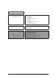
Parameter Data Formats Bit Byte 0 7 6 5 4 3 2 1 0 0 0 0 0 0 0 0 1 1 X‘0A’ or X‘06’ (Page Length) 2 AWRE ARRE TB RC ERR PER DTE DCR Default 1 1 1 0 1 0 0 0 Variable 1 1 1 1 1 1 1 1 3 Number of retries during READ Default X‘3F’ (=63 times) Variable X‘FF’ 4 Correctable Bit Length Default X‘E9’ (=233 bits) Variable X‘00’ 5 X‘00’ (Head Offset Count) 6 X‘00’ (Data Strobe Offset Count) 7 X‘00’ (Reserved) 8 Number of retries during WRITE Default X‘
4.1 Mode Parameters • • • • READ READ EXTENDED READ LONG SEND DIAGNOSTIC (Write/read test) • • • • WRITE WRITE AND VERIFY (Write operation) WRITE EXTENDED WRITE LONG a. AWRE (automatic write reallocation enabled) "1" : An "automatic alternate block allocation processing" operation is specified during execution of a write operation. "0" : An "automatic alternate block allocation processing" operation is prohibited during execution of a write operation.
Parameter Data Formats f. PER (post error) "1" : When several errors (errors related to the disk drive), which were recovered from normally through the IDD's error recovery processing, have been detected, a CHECK CONDITION status is reported when execution of that command is completed. In the sense data generated at this time, the sense key indicates "RECOVERED ERROR [=1]" and the content of the first error to be corrected successfully is reported.
4.1 Mode Parameters j. Correctable bit length This parameter indicates the burst error length (bit length) which it is possible to apply data correction according to the ECC to. It is impossible to change this parameter from the INIT. The IDD disregards the value specified in this parameter and operates according to the "Default" value. k.
Parameter Data Formats n. Recovery time limit This parameter specifies the maximum time that can be used by the TARG for error recovery processing, as a 1ms constant. The value specified in this parameter is the maximum permissible time for error recovery processing for each individual command. When both this parameter and the "Number of retries" parameter are specified, the parameter which specifies the shortest time must be given priority in application.
4.1 Mode Parameters Table 4.1 Combinations of error recovery flags (1 of 3) EER PER DTE DCR Error Recovery Procedure 0 0 0 0 1. Rereading is tried repeatedly up to the number of times specified in the "Read Retry Count", "Write Retry Count" or "Verify Retry Count" parameter. If possible, data correction is executed afterward according to the ECC. 2. When error recovery has succeeded, processing of the command is continued. 3. The contents of recovered errors are not reported. 4.
Parameter Data Formats Table 4.1 Combinations of error recovery flags (2 of 3) EER PER DTE DCR Error Recovery Procedure 0 1 1 0 1. Rereading is tried repeatedly up to the number of times specified in the "Read Retry Count", "Write Retry Count" or "Verify Retry Count" parameter. If possible, data correction is executed afterward according to the ECC. 2.
4.1 Mode Parameters Table 4.1 Combinations of error recovery flags (3 of 3) EER PER DTE DCR Error Recovery Procedure 1 1 0 0 1. When a correctable data check is detected, immediately, correction is executed according to the ECC. For data checks which cannot be corrected, rereading is tried repeatedly up to the number of times specified in the "Read Retry Count", "Write Retry Count" or "Verify Retry Count" parameter.
Parameter Data Formats 4.1.2 Disconnect/reconnect parameters (page code = 2) The format of the page descriptor in this MODE SELECT parameter is shown in Figure 4.2.
4.1 Mode Parameters Note: If transfer of this page descriptor is required by the MODE SENSE or MODE SENSE EXTENDED command, the IDD reports X '0E' as the page length (byte 1). However, if either X '0E' or X '0A' is specified for the page length in the MODE SELECT command, the IDD regards it as if the correct page length was specified.
Parameter Data Formats Note: If the value specified for the "buffer full ratio" or the "buffer empty ratio" is not within double the integral boundary of the logical data block length, the IDD rounds up the specified value to the value which is the nearest data block boundary. Also, if zero is specified in any of these parameters. If X’00’is specified, the IDD assigns an appropriate value for this parameter that is determined by IDD.
4.1 Mode Parameters 00b= Perform disconnection according to the instructions of other parameters without using DTDC. 01b= When a data transfer by the command is started, the target will never try disconnection until transmission of all the data to be transferred by the command is completed. The specified values in the "connect limit time" and "bus inactivity limit" fields are ignored during the data transfer. 10b= Reserved.
Parameter Data Formats 4.1.3 Format parameter (page code = 3) The Page descriptor format of this MODE SELECT parameter is shown in Figure 4.3.
4.1 Mode Parameters a. Parameters for specifying alternate processing areas for defective blocks (bytes 2 to 9) The following 4 parameters specify the position and number of spare sectors for performing defective block alternate allocation processing on the disk media. See Chapter 3, "Data Format" of Product Manual for details of the IDD's alternate block processing. • Track count/zone This parameter specifies the number of tracks a unit for alternating blocks. The INIT cannot clearly specify this value.
Parameter Data Formats c. Parameters specifying sector format (bytes 12 to 19) • Data byte length/physical sectors This parameter specifies the data length per 1 physical sector as the number of bytes. In the IDD, the data byte length per 1 physical sector is the same as the data byte length in 1 logical data block. The INIT can specify the value of this parameter at 0 or 512 to 528 bytes (4-byte boundary). If a value less than 512 bytes, the IDD sets a byte length of 512.
4.1 Mode Parameters 4.1.4 • HSEC (hard sectoring) When this bit is "1," it indicates that the data formatting method on the disk media is "hard sectoring." However, since the IDD uses only the "hard sectoring" method, this bit is disregarded. Furthermore, it is impossible to change this parameter. • RMB (removable medium) When this bit is "1," it indicates that the storage media of the disk drive can be replaced. When this bit is "0," it indicates that the storage media is fixed.
Parameter Data Formats Bit 7 6 5 4 3 2 1 0 0 0 0 0 0 1 0 0 Byte 0 1 (See the "Note") X‘16’, X‘12’ or X‘0A’ (Page Length) 2-4 Cylinder Count Default X‘00xxxx’ Variable X‘000000’ 5 Number of Heads Default X‘00xx’ Variable X‘0000’ 6-8 "Write Precompensation" Starting Cylinder Default X‘000000’ Variable X’000000’ 9-11 "Reduced Write Current" Starting Cylinder Default X‘000000’ Variable X‘000000’ 12-13 Drive Step Rate Default X‘0000’ Variable X‘0000’ 14-16 Land
4.1 Mode Parameters a. Cylinder count This parameter specifies the total number of cylinders configured in the user space on the disk media. This value includes the number of cylinders for alternate blocks specified in the "Alternate Track Count/Drive" parameter of the format parameters (Page code = 3). It is impossible to change this parameter. b. Number of heads This parameter indicates the number of data Read/Write heads in the disk drive. It is impossible to change this parameter.
Parameter Data Formats Bit Byte 0 7 6 5 4 3 2 1 0 0 0 0 0 0 1 1 1 1 (See the Note.) X‘0A’ (Page Length) 2 (Reserved) EER PER DTE DCR Default 0 0 0 0 1 0 0 0 Variable 0 0 0 0 1 1 1 1 3 Number of retries during VERIFY. Default X‘3F’ Variable X‘FF’ 4 Correctable Bit Length Default X‘E9’ (=233 bits) Variable X‘00’ 5-9 X‘0000000000’ (Reserved) 10-11 Recovery Time Limit Default X‘7530’ Variable X‘FFFF’ Figure 4.
4.1 Mode Parameters b. Number of retries during VERIFY This parameter specifies the number of times reading of the disk media should be retried when a "Data Check" type error is detected in a read operation. the number of retries specified by this parameter is the maximum number of times reading of each individual data area in each logical data block is retried. The IDD retries reading the data area in each data block the specified number of times.
Parameter Data Formats Bit 7 6 5 4 3 2 1 0 0 0 0 0 1 0 0 0 Byte 0 1 X‘0A’ or X‘12’ (Page Length) 2 IC ABPF CAP DISC SIZE WCE MS RCD Default 0 0 0 1 0 1 0 0 Variable 1 0 0 0 0 1 0 1 3 Demand Read Retention Priority Write Retention Priority Default 0 0 0 0 0 0 0 0 Variable 0 0 0 0 0 0 0 0 4-5 Pre-fetch inhibit block count Default X‘FFFF’ Variable X‘0000’ 6-7 Minimum pre-fetch Default X‘0000’ Variable X‘0000’ 8-9 Maximum pre-fetch
4.1 Mode Parameters a. RCD (read cache disable) This bit can be specified, and its operation is as specified. This bit specifies whether or not to activate the cache operation for a read command. "1" : Prohibits operation of the Look-Ahead cache function. The IDD reads ahead all of the data requested by the READ command or READ EXTENDED command from the disk and transfers it to the INIT. Moreover, it does not read ahead data blocks after the requested data.
Parameter Data Formats d. SIZE (size enable) (not supported) "1" : Divides the data buffer in accordance with the value specified for the cache segment size (bytes 14, 15). "0" : Divides the data buffer in accordance with the value specified for the number of cache segments (byte 13). This bit cannot be changed. The IDD disregards the specification in this bit and operates according to the "Default" value (= "0"). e.
4.1 Mode Parameters "F" : Data put into the cache during a WRITE or WRITE and VERIFY command was not replaced if there is ohter data in the cache that was placed into the cache by other means and it may be replaced. "1" : Data put into the cache during a WRITE or WRITE and VERIFY command was replaced sooner than data placed into the cache by other means. "0" : Indicates the device server was not distinguish between retaining the indicated data and data placed into the cache memory by other means. i.
Parameter Data Formats "1" : Requests that the device server not read into the buffer any logical blocks beyond the addressed logical blocks. "0" : The device server continues to read logical blocks into the buffer beyond the addressed logical blocks. n. FSW (force sequential write) (not supported) This bit specifies how to write multiple blocks. "1" : If the IDD writes multiple blocks, this indicates that data are recorded on the disk media in the order in which they are transferred from the INIT.
4.1 Mode Parameters cache segments are occupied by data to be retained. If the number is at least one, caching functions in the other segments need not be impacted by cache misses to perform the SCSI buffer function. The impact of this field equals 0 or the sum of this field plus this field greater than the buffer size is vendor-specific. This bit is not supported for the IDD. The IDD disregards the specification in this bit. 4.1.
Parameter Data Formats a. TST (Task Set Type) This field specifies the type of task set defined below. Value Description 000b Task set per logical unit for all initiators 001b Task set per initiator per logical unit 010b-111b Reserved The IDD operates according to "000b". If other value is specified in this field, the IDD reports a "CHECK CONDITION" status (ILLEGAL REQUEST [=5] / Invalid parameter in list [=26-00]). b.
4.1 Mode Parameters Despite the commands whose specified LBAs are overlapped, the IDD conducts reordering operation. Therefore the INIT who specifies "1" in this field shall ensure Data Integrity itself. The IDD disregards "1" in this field and operates as if "0" were specified. When “F” is specified in this parameter, the IDD prohibits to order queued commands.
Parameter Data Formats g. RAC (Report Check) (not supported) The IDD is not supported in this bit. Therefore, the IDD always report "0", and ignore specified value. h. SWP (Soft Write Protect) (not supported) This bit specifies whether or not to execute for the device server write operation to the medium. The IDD is not supported this bit. Therefore, the IDD always report "0", and ignore specified value. i.
4.1 Mode Parameters 4.1.
Parameter Data Formats If this parameter is issued, only the format parameter of the zone specified by the MODE SENSE command can be referred to without changing the number of accessible blocks. Also, if a MODE SENSE command with a SP = "1" that includes a notch page is issued, the current value is reported for this page and the zone value which is the object is reported if Page 3 is notched, then the command is terminated normally.
4.1 Mode Parameters • Starting Boundary This field is enabled by the MODE SENSE command. This field indicates the beginning of the active notch or, if the active notch is zero, the beginning of the logical unit (IDD). • Ending Boundary This field is valid in the MODE SENSE command. This field indicates the ending of the active notch or, if the active notch is zero, the ending of the logical unit (IDD).
Parameter Data Formats The log errors bit (LogErr) of zero indicates that the logging of informational exception conditions within a target is vendor specific. A LogErr bit of one indicates the target logs informational exception conditions. A Test bit of one creates a false device failure at the next interval time, if the DExcpt bit is not set. When the Test bit is one, the MRIE and Report count fields apply as if the Test bit were zero.
4.1 Mode Parameters MRIE X’00’ Descriptor No reporting of informational exception conditions: This method instructs the target to not report informational exception conditions. X’01’ Asynchronous event reporting: This method instructs the target to report informational exception conditions by using the rules for asynchorous event reporting as described in the SCSI-3 Architecture Model and the relevant Protocol Standard.
Parameter Data Formats The "Interval Timer" field indicates the period in 100 millisecond increments for reporting that an informational exception condition has occurred. The target does not report informational exception conditions more frequency than the time specified by the "Interval Timer" field and as soon as possible after the timer interval has elapsed. After the informational exception condition has been reported the interval timer is restarted.
4.2 Log Parameters a. RPR (rounded parameter report) This bit stipulates the operation in the case where rounding up or rounding down processing of a MODE SELECT parameter is performed. "1" : If rounding up or rounding down processing of parameters in the MODE SELECT command has been performed, a CHECK CONDITION status is reported. "0" : Even if rounding up or rounding down processing has been performed, a GOOD status is reported and the command is terminated normally.
Parameter Data Formats 4.2.1 Supprot log page (X'00') The supported log page returns the list of log pages implemented by the drive.
4.2 Log Parameters 4.2.
Parameter Data Formats • Data Underrun Count of data underruns which occur during write operation when a buffer empty condition prevents continued transfer of data to the media from the buffer. The drive does not support this field due to a hardware limitation. Zero is always reported. • Data Overrun Count of data overruns which occur during read operation when a buffer full condition prevents continued transfer of data from the media to the buffer.
4.2 Log Parameters 4.2.3.2 Write errors recovered with possible delays (Page 02, Code 0001) Bit Byte 4 7 6 5 4 3 2 1 0 (MSB) X'0001' (Parameter code) (Errors Recovered With Possible Delays) 5 6 DU DS TSD ETC 0 0 0 0 7 TMC 0 0 (LSB) LBIN LP 0 0 X'04' (Parameter Length) 8 (MSB) 9 Counter Value 10 11 (LSB) The Counter Value indicates the count of all recovered write errors that would not be reported to the initiator during write operations, because possible delay is incurred.
Parameter Data Formats 4.2.3.4 Total posted recoverable write errors (Page 02, Code 0003) Bit 7 Byte 4 6 5 4 3 2 1 0 (MSB) X'0003' (Parameter code) (Total Posted Recoverable Errors) 5 6 DU DS TSD ETC 0 0 0 0 7 TMC 0 0 (LSB) LBIN LP 0 0 X'04' (Parameter Length) 8 (MSB) 9 Counter Value 10 11 (LSB) The Counter Value indicates the count of all posted recovered (01/xx/xx) errors to the interface during write operations. 4.2.3.
4.2 Log Parameters 4.2.3.6 Total posted unrecoverable write errors (Page 02, Code 0006) Bit Byte 4 7 6 5 4 3 2 1 0 (MSB) X'0006' (Parameter code) (Total Posted Unrecoverable Errors) 5 6 DU DS TSD ETC 0 0 0 0 7 TMC 0 0 (LSB) LBIN LP 0 0 X'04' (Parameter Length) 8 (MSB) 9 Counter Value 10 11 (LSB) The Counter Value indicates the count of all posted unrecovered errors (03/xx/xx) to the interface during write operations. 4.2.
Parameter Data Formats 4.2.4.1 Read errors recovered without delays (Page 03, Code 0000) Bit Byte 4 7 6 5 4 3 2 1 0 (MSB) X'0000' (Parameter code) (Errors Recovered Without Delays) 5 6 DU DS TSD ETC 0 0 0 0 7 TMC 0 (LSB) LBIN LP 0 0 0 X'04' (Parameter Length) 8 (MSB) 9 Counter Value 10 11 (LSB) The Counter Value indicates the count of all recovered read errors that would not be reported to the initiator during read operations, because no delay is incurred. 4.2.4.
4.2 Log Parameters 4.2.4.3 Total posted read errors (Page 03, Code 0002) Bit Byte 4 7 6 5 4 3 2 1 0 (MSB) X'0002' (Parameter code) (Total Posted Errors) 5 6 DU DS TSD ETC 0 0 0 0 7 (LSB) TMC 0 0 LBIN LP 0 0 X'04' (Parameter Length) 8 (MSB) 9 Counter Value 10 11 (LSB) The Counter Value indicates the count of all posted errors to the interface during read operations. The value includes the count of all posted verify errors to the interface (page X'05', Parameter code X'0002').
Parameter Data Formats 4.2.4.5 Total read bytes processed (Page 03, Code 0005) Bit 7 Byte 4 6 5 4 3 2 1 0 (MSB) X'0005' (Parameter code) (Total Bytes Processed) 5 6 DU DS TSD ETC 0 0 0 0 7 (LSB) TMC 0 0 LBIN LP 0 0 X'0A' (Parameter Length) 8 (MSB) 9 ~ ~ ~ ~ ~ ~ Total Write Bytes Processed (10 bytes) 16 17 (LSB) The Total Read Bytes Processed indicates the total processed bytes during read operation. The bytes includes the total processed bytes during verify operation.
4.2 Log Parameters 4.2.5 Verify error count page (X'05') Bit Byte 0 7 6 5 4 3 2 1 0 0 0 0 0 0 1 0 1 1 0 1 X‘00’ (Reserved) 2 Page Length (MSB) 3 Page Length (LSB) All of the following parameters have this header. Page Length will be defined based on the value of Parameter Pointer. (CDB 5-6) 4.2.5.
Parameter Data Formats 4.2.5.
4.2 Log Parameters 4.2.5.4 Total posted recoverable verify errors (Page 05, Code 0003) Bit 7 Byte 4 6 5 4 3 2 1 0 (MSB) X'0003' (Parameter code) (Total Posted Recoverable Errors) 5 6 DU DS TSD ETC 0 0 0 0 7 TMC 0 0 (LSB) LBIN LP 0 0 X'04' (Parameter Length) 8 (MSB) 9 Counter Value 10 11 (LSB) The Counter Value indicates the count of all posted recovered (01/xx/xx) errors to the interface during verify operations. 4.2.5.
Parameter Data Formats 4.2.5.6 Total posted unrecoverable verify errors (Page 05, Code 0006) Bit Byte 4 7 6 5 4 3 2 1 0 (MSB) X'0006' (Parameter code) (Total Posted Unrecoverable Errors) 5 6 DU DS TSD ETC 0 0 0 0 7 TMC 0 0 (LSB) LBIN LP 0 0 X'04' (Parameter Length) 8 (MSB) 9 Counter Value 10 11 (LSB) The Counter Value indicates the count of all posted unrecovered errors (03/xx/xx) to the interface during verify operations. 4.2.
4.2 Log Parameters The Counter Value indicates the count of all non-medium errors (01/xx/xx, 02/xx/xx, 04/xx/xx, 05/xx/xx, 06/xx/xx, 07/xx/xx, 09/xx/xx and 0B/xx/xx) posted to the interface. Implementation: If a non-medium error is posted, it will force a save of all error log pages information. 4.2.7 Temperature page (X'0D') Bit Byte 0 7 6 5 4 3 2 1 0 0 0 0 0 1 1 0 1 1 X‘00’ (Reserved) 2 Page Length (MSB) 3 Page Length (LSB) All of the following parameters have this header.
Parameter Data Formats 4.2.7.
4.2 Log Parameters 4.2.8.
Parameter Data Formats The Accounting date specified by parameter code 0002h is a parameter that may be savable using a LOG SELECT command to indicate when the device was placed in service. If the parameter is not yet set or is not settable, the default value placed in the parameter field shall be 6 ASCII blank characters (20h). The field shall not be checked for validity by the device server. 4.2.8.
4.2 Log Parameters The Accumulated start-stop cycles is a parameter provided by the device sever. The accumulated start-stop cycles parameter shall not be savable by the application client using the LOG SELECT command. The parameter value is a 4-byte binary number. The value indicates how many start-stop cycles the device has detected since its date of manufacture.
Parameter Data Formats The values stored in the General usage parameter bytes represent data sent to the device server in a previous LOG SELECT command. If a previous LOG SELECT command has not occurred, the data is zero. 4.2.10 Self-test result page (X'10') Bit Byte 0 7 6 5 4 3 2 1 0 0 0 0 1 0 0 1 0 1 X‘00’ (Reserved) 2 Page Length (MSB) 3 Page Length (LSB) All of the following parameters have this header. Page Length will be defined based on the value of Parameter Pointer.
4.2 Log Parameters 4.2.11 SMART status page (X'2F') [Fujitsu unique page] Bit Byte 0 7 6 5 4 3 2 1 0 0 0 1 0 1 1 1 1 1 X‘00’ (Reserved) 2 Page Length (MSB) 3 Page Length (LSB) 4 ~ ~ ~ ~ ~ ~ SMART Status Parameter n This page contains parameters which allow the application client to check the predictive drive failure condition of the IDD. The application client can check whether the IDD has predicted a drive failure by periodically reading out this page.
This page is intentionally left blank.
CHAPTER 5 Sense Data Error Recovery Methods 5.1 Sense Data 5.2 INIT Error Recovery Methods (Recommended) 5.3 Disk Drive Error Recovery Processing In this chapter, the configuration and contents of sense data reported to the INIT (initiator) when an error occurs, etc., key information for interpreting error states, recommended procedures for error recovery processing that should be executed by software in the INIT and error recovery processing executed internally by the IDD are described.
Sense Data Error Recovery Methods Bit Byte 0 7 6 5 Valid 4 3 2 1 0 X ‘70’ or X ‘71’ (Error Code) 1 X‘00’ 2 0 3 MSB 0 ILI 0 Sense Key 4 5 Information 6 LSB 7 8 X ‘28’ (Additional Sense Data Length) MSB 9 Basic Information 10 Command Inherent Information 11 LSB 12 Sense Code 13 Sub-sense Code 14 X‘00’ 15 SKSV 16 Sense Key Inherent Information 17 18 0 0 0 19 0 IDD SCSI ID CDB Operation Code 20 Additional Information Detailed Information 47 Figure 5.1 5.1.
5.1 Sense Data (2) Error code This field shows the format and type of sense data. The IDD always displays X ‘70’ (current error) or X ‘71’ (deferred error), which has the meaning “expanded sense data format” in this field. (3) ILI (incorrect length indicator) When this bit is “1,” it indicates that the transfer byte length requested in the command did not coincide with the data block length on the disk media.
Sense Data Error Recovery Methods (8) Sense code, sub-sense code The codes which indicate the reason for the error displayed by the sense key in detail are reported in these fields. The INIT can decide procedures for error recovery according to the sense key and these fields. The sense code and sub-sense code are defined in Table 5.2.
5.1 Sense Data Table 5.1 Sense Key Name Sense key Explanation 0 NO SENSE The specific sense key does not exist. 1 RECOVERED ERROR 1) Indicates that the command which was executed last was terminated normally with a recovery operation by the IDD. If multiple errors which were successfully recovered from during processing of a single command occurred, the last error to have occurred is reported. 2) Rounding processing of the MODE SELECT parameter was performed.
Sense Data Error Recovery Methods Table 5.2 Sense key C* Q* 00 00 06 I/O process terminated I/O was interrupted by the Terminated I/O Process message. 0 01 00 No index/sector signal The target sector was not detected by the sector counter within the specified time. 4 03 00 Peripheral device write fault A write operation to the disk media was terminated abnormally. • Off track during write.
5.1 Sense Data Table 5.2 Q* 13 00 Sync Byte not found for Data field SB (Sync Byte) could not be detected in the Data area. 1, 3, B 14 00 Record entity not found Expected data from a sector was undetected. (LBA compare error detected by FMT) 1, 3, B 01 Record not found The target data block (sector) could not be detected. 01 Mechanical positioning Error A seek error occurred in the drive. 02 Positioning Error detected LBA did not match due to Cylinder number’s mismatch.
Sense Data Error Recovery Methods Table 5.2 Sense and subsense codes (3 of 5) Name Sense key Explanation C* Q* 1F 00 Partial Defect List Transfer Read Defect Data command (37h) cannot transfer all the Defect data in the target because the numbers of defect exceeded the maximum. 1 20 00 Invalid command operation code CDB byte 0 (operation code) is illegal. 5 21 00 Logical block address out A logical block address which exceeds the drive's maximum value of range was specified.
5.1 Sense Data Table 5.2 Sense and subsense codes (4 of 5) C* Q* 3D 00 Invalid bits in IDENTIFY "1" was specified in the reserve bit of the IDENTIFY message. message 5 3E 03 Logical unit failed SelfTest 4 04 Logical unit unable to update The IDD failed to update the Self-Test result log 4 01 Microcode has been changed Microcode was changed by another INIT. 6 02 Changed operating definition Operating definition was changed. 6 05 Device identifier changed Device identifier was changed.
Sense Data Error Recovery Methods Table 5.2 Sense and subsense codes (5 of 5) Explanation Sense key Select/Reselect failure A response wait time-out from the INIT was detected in the RESELECTION phase. B 00 SCSI parity error A parity error was detected on the SCSI data bus. B 48 00 INITIATOR DETECTED The INITIATOR DETECTED ERROR message was received from ERROR message received the INIT. B 49 00 Invalid message error An unsupported or inappropriate message was received.
5.2 INIT Error Recovery Methods (Recommended) 5.1.3 Sense data additional information Bytes 18 to 47 of sense data are defined as a Fujitsu unique field, and indicate the additional information which is explained below. (1) IDD SCSI ID This field shows the SCSI ID of the very IDD which generated the sense data. (2) CDB operation code This field indicates the operation code (the value in the first byte of the CDB) of the command where the error occurred.
Sense Data Error Recovery Methods Command issue END status received ? Yes Yes GOOD BUS FREE error ? Yes Normal end No Yes To item (1) BUSY No No No Timeout ? QUEUE FULL Yes Yes To item (1) No PRESERVATION CONFLICT Yes To item (2) No See item (3). See item (4). Issue of REQUEST SENSE command Section5.3.2 4.3.2 ToToSection Figure 5.
5.2 INIT Error Recovery Methods (Recommended) (2) RESERVATION CONFLICT status This status shows, under a multi-initiator environment, that the IDD is currently reserved by another INIT, and cannot be used until that reserved status is released. The period over which the reserved status continues should be managed by the system, but normally, an INIT that receives this status reissues the original command after waiting an appropriate length of time.
Sense Data Error Recovery Methods The cause of this error is the occurrence of an unrecoverable error on the SCSI bus, the occurrence of a serious protocol error, etc. For details concerning the causes of errors, see Chapter 3, "SCSI Bus Error Recovery Processing" in Chapter 3 of the "SCSI Physical Specifications." When this error is detected, the INIT should issue the REQUEST SENSE command and gather sense data then judge the error recovery method according to the contents of the sense data (see Section 4.
5.2 INIT Error Recovery Methods (Recommended) Table 5.3 Sense data error classification (2 of 4) K* C* Q* Outline of Error L* Recovery Method (See Table 4.4.) 3 11 13 14 xx 00 01 Unrecovered read error Sync byte not found for data field No record found These errors were detected during accessing of the disk media, but they were errors which could not be recovered from through the IDD's retry processing.
Sense Data Error Recovery Methods Table 5.3 Sense data error classification (3 of 4) L* Recovery Method (See Table 4.4.) Invalid command operation code Logical block address out of range Invalid field in CDB Logical unit not supported Invalid field in parameter list There is an error in the command specification contents. None 2 00 00 Invalid bits in IDENTIFY message Initiator's SCSI ID not identified An error was detected in the SCSI protocol in the command execution sequence.
5.2 INIT Error Recovery Methods (Recommended) Table 5.3 K* C* Q* Sense data error classification (4 of 4) Error contents L* Recovery method (See Table 4.4.
Sense Data Error Recovery Methods Table 5.4 Recovery Method 5 6 7 8 Error Recovery Processing Procedures (2 of 5) Recovery Processing Procedure 1) After waiting about 1 second, reissue the original command (Retry). 2) If it doesn't recover after 10 retries, perform recovery method 1. 1) Reissue the original command. (Retry) 2) If it doesn't recover after 10 retries, perform recovery method 3. 1) Reissue the original command.
5.2 INIT Error Recovery Methods (Recommended) Table 5.4 Recovery method 12 Error recovery processing procedures (3 of 5) Recovery processing procedure 1) Set the "Number of Retries" value in the MODE SELECT parameters at the "Default" value. 2) Reissue the original command (Retry). (Note) 3) If the error is not recovered from after the first retry, issue the REZERO UNIT command. 4) Reissue the original command (Retry). (Note) 5) If the error is not recovered from, perform one of the following.
Sense Data Error Recovery Methods Table 5.4 Recovery method 18 Error recovery processing procedures (4 of 5) Recovery processing procedure 1) Issue the MODE SENSE or MODE SENSE EXTENDED command and confirm the values of the disk media data format related parameters (Block descriptor, Page 3: Format parameters, Page 4: Drive parameters). 2) If the parameter values are correct, issue the FORMAT UNIT command and initialize the entire disk media surface.
5.2 INIT Error Recovery Methods (Recommended) Table 5.4 Error recovery processing procedures (5 of 5) Recovery method 26 27 Recovery processing procedure 1) Issue the LOG SENSE command and read the "Current" values of the LOG SELECT parameters. 2) Search for any parameter values which exceed the threshold value or have reached the maximum value, then issue the LOG SELECT command from the INIT and perform resetting. 3) Reissue the original command.
Sense Data Error Recovery Methods 5.3 Disk Drive Error Recovery Processing This section explains concerning error recovery processing methods and procedures executed by the IDD for each type of disk drive related error. The INIT can control the error recovery processing methods executed by the IDD using the MODE SELECT parameters. 5.3.
5.3 Disk Drive Error Recovery Processing If error correction is permitted but immediate correction is not permitted (DCR = 0, EER = 0), reading of data as in item (2) is retried up to the number of times specified in the other MODE SELECT parameters ("Number of Retries during Read" or "Number of Retries during Write").
Sense Data Error Recovery Methods Remark: (2) 1. When this function is specified (ARRE = "1"), the EER flag's specification in the MODE SELECT parameter is made invalid and Read retry processing is performed up to the number of times specified in the "Number of Retries during Read" parameter. If "0" is specified in the DCR flag, correction processing of the data is performed afterward (see Section 5.3.1 (3)).
5.3 Disk Drive Error Recovery Processing Sectors to be made AWRE shall be following: • • • • the sector where the error occurs and the latter sectors and, the sectors whose data are logically continual and stored in Cache, the sectors which will be processed in this Write command and, the sectors which locate between erroneous Servo –1 and +1 (including Split sector) This function is also applied for the sector which has already been re-assigned. Remark: 1. 5.3.
Sense Data Error Recovery Methods b. Verify Error Recovery Parameters (Page Code = 7) • EER (enable early recovery) • PER (post error) • DTE (disable transfer on error) • DCR (disable correction) • Number of retries during verify (See Table 5.5) c. Additional Error Recovery Parameters (Page Code = 21) • Number of retries during seek error (See Table 5.5) Table 5.
CHAPTER 6 Disk Media Management 6.1 Defect Management 6.2 Disk Media Initialization 6.3 Data Block Verification Methods (Recommended) 6.4 Alternate Block Allocation Processing In this chapter, disk media defect management methods, treatment methods for media defects which occur during operation, reinitialization procedures and other disk media management methods are discussed.
Disk Media Management (2) Alternate block allocation Alternate data blocks are allocated in defective sector units for defective data blocks (= sectors) on the disk media by the IDD's internal defect management methods. a. Spare sector area Spare sectors for allocation as alternate blocks are secured in both of the following areas or alternate cell. When the INIT initializes the disk media, it can specify the spare sector area to be prepared on the disk drive and the size of that area.
6.2 Disk Media Initialization • Alternate block allocation processing during FORMAT UNIT command execution With the FORMAT UNIT command, alternate block allocation is done by sector slip processing until all the spare sectors within the same cell have been used up for defective sectors included in the type of defect list (P, G or D) specified in the command.
Disk Media Management (1) Issuing the MODE SELECT command The MODE SELECT or MODE SELECT EXTENDED command is issued and the format attributes on the disk media are specified. The necessary parameters at this time are as follows. a. Block descriptor The logical data block size (byte length) is specified in the "Data block length" field. Also, when desiring to clearly specify the logical data block count, specify that value in the "Data block count" field.
6.2 Disk Media Initialization 6.2.2 Re-initialization The INIT can reinitialize the disk drive after it has been operated using the FORMAT UNIT command. Note: If it is necessary after reinitialization to restore the data that were stored on the disk media, it is necessary to save the data before executing reinitialization, then execute data restore using system software after reinitialization.
Disk Media Management 6.3 Data Block Verification Methods (Recommended) The recommended procedure for verifying from the INIT the normalcy of logical data blocks located on the disk media is as shown below. It is desirable for the INIT to verify the data blocks after initialization of the disk media is completed or when executing alternate block allocation processing by the REASSIGN BLOCKS command.
6.4 Alternate Block Allocation Processing (3) Reading and verification of data Issue the READ, READ EXTENDED or VERIFY command and verify that the data written to the disk media in item (2) were read correctly. To verify reading of data, it is recommended that reading of the same data block be done at lease 2 times, but the number of times verification is performed is determined by the conditions on the system.
Disk Media Management The alternate block allocation history (defect position information) is registered as an addition to the defect list (G List). Therefore, when reinitializing the hard disk with the FORMAT UNIT command (see Section 6.2.2), if use of the G List is specified, defect processing can be performed which reflects the operation results up to that time.
Glossary Axial acceleration Acceleration in the recording layer along the line perpendicular to the disk reference surface at a specified rotation speed. Axial acceleration is detected by optical means. Bus Condition This is an asynchronous condition for changing the status transition on the SCSI bus. There are two types, the ATTENTION condition and the RESET condition. Bus Phase This is the name given to the SCSI bus state.
Glossary Initiator (INIT) This is a SCSI device which initiates input and output operations on the SCSI bus. In this manual, initiator has been abbreviated to "INIT." Logical Unit This is the device unit which is the object of input/output operations on the SCSI bus. LUN Logical Unit Number This is the serial number which identifies a logical unit.
Glossary status, this is information generated by the target for reporting detailed information on that status. Sense Key This is a 4-bit code displayed in the sense data. It contains information for classifying the type of error that was detected. Status This is 1 byte of information reported to the initiator by the target device when execution of each command is completed, which displays the command's completion state.
This page is intentionally left blank.
Acronyms and Abbreviations A ACK ATN AWG Acknowledge Attention American Wire Gauge L LSB LUN Least significant byte Logical unit number M B BSY Busy MSB MSG C C/D CCS CDB Control/data Common command set Common descriptor block Most significant byte Message O OEM Original equipment manufacturer R D DB DBP DC Data bus Data Bus Parity Direct current E EIA REQ RST Request Reset S SCSI SDTR SEL Small Computer System Interface Synchronous data transfer request Select Engineering Industries Ass
This page is intentionally left blank.
Comments concerning this manual can be directed to one of the following addresses: FUJITSU LIMITED Business Planning Solid Square East Tower 580 Horikawa-cho,Saiwai-ku, Kawasaki, 210-0913, Japan TEL: 81-44-540-4056 FAX: 81-44-540-4123 FUJITSU COMPUTER PRODUCTS OF AMERICA, INC. 2904 Orchard Parkway, San Jose, California 95134-2009, U.S.A. TEL: 1-408-432-6333 FAX: 1-408-432-3908 FUJITSU CANADA INC. 2800 Matheson Blvd.
This page is intentionally left blank.
Index 10-byte CDB basic format 1-2 12-byte CDB basic format 1-2 6-byte CDB basic format 1-1 A accounting date 4-53 ACE 3-18 active notch 4-32 additional data length 3-5 additional error recovery parameter 4-36, 5-25 additional sense data length 5-3 AGD 3-18 AIP checking enabled 3-18 generation disabled 3-18 alternate area 1-32 alternate block allocation 6-2 method 6-2 processing 6-2, 6-7 processing by REASSIGN BLOCKS command 6-3 processing during FORMAT UNIT command execution 6-2 alternate cylinder 6-2 al
Index changing reserve condition 3-39 CHECK CONDITION status 1-7 C list 3-76, 6-1 clocking field 3-8 CmdDt 3-3 command support data 3-9 cleared by another INIT 1-20 code 1-3 completion wait time-out 5-13 format 1-1 inherent information 5-3 link 1-9 other than INQUIRY command 1-20 other than REQUEST SENSE command 1-20 queuing function 1-16 specification 3-1 support data 3-9 supported data 3-3 that can be executed even in not ready state 1-25 with executing disconnect process 1-11 combination of error recover
Index disconnect processing 1-11, 1-12 exception 1-14 procedure after COMMAND phase execution 1-13 procedure after data transfer execution 1-13 disconnect/reconnect parameter 4-10 disconnect time limit 4-12 disk drive error and number of retries 5-25 recovery processing 5-21 disk media initialization 6-3 management 6-1 D list 3-76, 3-78, 6-1 DPOFUA bit 3-32 DPRY 3-78 DQue 4-30 DRA 4-25 drive parameter 4-17, 6-4 DS 3-47 DTDC 4-12 DTE 4-4, 4-20 DU 3-47 E EBF 4-34 EBOS 3-110 echo buffer 3-106, 3-110 descripto
Index H handling illegal CDB 1-5 hard sectoring 4-17 header 3-16, 3-22, 3-32, 3-78, 3-89 header + data with address specification 3-108 without address specification 3-103, 3-107 head offset count 4-5 HSEC 4-17 I IC 4-24 IDD SCSI ID 5-11 wide data transfer request 3-16 if disconnecting after final data transfer is completed 1-13 if disconnecting during data transfer 1-13 if disconnect processing in impossible 1-17 if IDD is reserved 1-17 ILI 5-3 illegal LUN specification 1-24 Immed 3-79 immediate 3-79 cas
Index mode=0, 0, 1, 1 3-109 mode=0, 1, 0, 0 3-104 mode=0, 1, 0, 1 3-105 mode=0, 1, 1, 0 3-105 mode=0, 1, 1, 1 3-106 mode=1, 0, 1, 0 3-106, 3-110 mode=1, 0, 1, 1 3-110 mode parameter 4-1 changed 1-20 MODE SELECT 3-19 command 3-23, 6-5 MODE SELECT EXTENDED 3-26 command parameter configuration 3-28 MODE SELECT parameter 2-5, 4-2, 4-10, 4-14, 4-18, 4-20, 4-22, 4-28, 4-33, 4-36 of IDD 3-25 structure 3-21 MODE SENSE 3-28 command 3-31 data type specification 3-30 MODE SENSE EXTENDED 3-34 command 3-35 MRIE 4-34 MS
Index parameter specification 3-94 parameter specifying sector format 4-16 track format 4-15 PER 4-4, 4-20 Perf 4-34 persistent reservation type 3-54 code 3-55 PERSISTENT RESERVE IN 3-49 parameter data for READ KEYS 3-51 parameter data for READ RESERVATIONS 3-52 PERSISTENT RESERVE OUT 3-56 command service action code 3-58 parameter list 3-58 service action 3-57 service action and valid parameter 3-60 phase CRC 3-17 PHSCRC 3-17 physiucal sector address format 3-81 P list 3-76, 6-1 bit 3-89 post error 4-4, 4-
Index object and third party release function 3-41 RELEASE EXTENDED 3-42 removable medium 4-17 report check 4-30 REPORT DEVICE IDENTIFIER 3-62 report log exception condition 4-29 REPORT LUNS 3-60 REQUEST SENSE 1-17, 3-42 command 1-21 reselection retry 3-17 reselection timeout delay 3-18 RESERVATION CONFLICT status 1-8, 5-13 RESERVE 3-37 reserved by Fujitsu 4-37 reserved operation code 1-24 RESERVE EXTENDED 3-40 reserve right and third party reserve function 3-38, 3-39 reset processing 1-27 during write 1-28
Index spindle motor start delay time 3-18 SSEC 4-16 standard INQUIRY data 3-3, 3-4 starting boundary 4-33 start specification 3-37 start-stop cycle counter 4-54 page 4-52 START/STOP UNIT 3-36 status byte 1-6 stop format 3-79 stop specification 3-37 STPF 3-79 sub-sense code 5-4 superseding reserve 3-39 support 3-9 log page 4-38 supported function 3-6 SURF 4-17 surface addressing 4-17 SWP 4-30 SYNCHRONIZE CACHE 3-74 synchronous data transfer request 3-17 synchronous mode data transfer 1-15 T tagged queuing 1
Index WP bit 3-32 WRITE 3-67 WRITE AND VERIFY 3-69, 4-20 WRITE BUFFER 3-102 command 3-103 write cache 2-10 enable 4-23 write error count page 4-40 write errors recovered without delay 4-40 with possible delay 4-41 WRITE EXTENDED 3-68 WRITE LONG 3-112 write operation 2-3 write retention priority 4-24 WRITE SAME 3-113 writing data pattern 6-6 C141-E167 X X'00' X'01' X'02' X'03' X'05' X'06' X'0D' X'0E' X'0F' X'10' X'2F' X'38' 4-38 4-39 4-40 4-43 4-47 4-50 4-51 4-52 4-55 4-56 4-57 4-57 IN-9
This page is intentionally left blank.
READER’S COMMENT FORM Your comments or suggestions on this document are cordially solicited. For any comments and suggestions you may have, please complete and submit this form to your FUJITSU representative. The comments and suggestions will be used in planning future editions. Thank you for your cooperation.
This page is intentionally left blank.