C141-E237-01EN MAX3147RC MAX3073RC MAX3036RC HARD DISK DRIVES PRODUCT/MAINTENANCE MANUAL
FOR SAFE OPERATION Handling of This Manual This manual contains important information for using this product. Read thoroughly before using the product. Use this product only after thoroughly reading and understanding especially the section "Important Alert Items" in this manual. Keep this manual handy, and keep it carefully. FUJITSU makes every effort to prevent users and bystanders from being injured or from suffering damage to their property. Use the product according to this manual.
REVISION RECORD Edition Date published 01 Revised contents July, 2005 Specification No.
Related Standards Product specifications and functions described in this manual comply with the following ANSI (*1) standards. Document number Title T10/1236D Rev.20 [NCITS.351:2001] SCSI Primary Commands-2 (SPC-2) T10/996D Rev. 8c [NCITS.306:1998] SCSI-3 Block Commands (SBC) T10/1157D Rev. 24 SCSI Architecture Model-2 (SAM-2) T10/1561D Rev. 14 SCSI Architecture Model-3 (SAM-3) T10/1562D Rev. 05 Serial Attached SCSI (SAS) T10/1601D Rev. 07 Serial Attached SCSI Model-1.1 (SAS 1.
Preface This manual describes MAX3147RC, MAX3073RC, and MAX3036RC 3.5" type hard disk drives with an embedded Serial Attached SCSI (SAS). This manual details the specifications and functions of the above disk drive, and gives the requirements and procedures for installing it into a host computer system. This manual is written for users who have a basic understanding of hard disk drives and their use in computer systems. The MANUAL ORGANIZATION section describes organization and scope of this manual.
Preface CONVENTIONS USED IN THIS MANUAL MAX3147RC, MAX3073RC, and MAX3036RC disk drives are described as "the hard disk drives (HDD)", "the disk drive" or "the device" in this manual. Decimal number is represented normally. Hexadecimal number is represented as X'17B9', 17B9h or 17B9H. Binary number is represented as "010". Conventions for Alert Messages This manual uses the following conventions to show the alert messages. An alert message consists of an alert signal and alert statements.
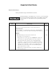
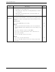
Important Alert Items Important Alert Messages The important alert messages in this manual are as follows: A hazardous situation could result in minor or moderate personal injury if the user does not perform the procedure correctly. Also, damage to the product or other property, may occur if the user does not perform the procedure correctly. Task Installation Alert message Page Damage Never remove any labels from the drive or deface them in any way.
Important Alert Items Task Installation Alert message 2. When dismounting the drive which is mounted on the system while power is not supplied to it. Page 5-10 • Dismount the drive using the drive mounting/dismounting mechanism, etc. of the system. • When storing or transporting the drive, put it in the antistatic bag (refer to Section 5.1). Diagnostics and Maintenance Data loss Save data stored on the disk drive to other media before requesting repair.
MANUAL ORGANIZATION PRODUCT/ MAINTENANCE MANUAL (This manual) INTERFACE SPECIFICATIONS C141-E237 1. 2. 3. 4. 5. 6. 7. General Description Specifications Data Format Installation Requirements Installation Diagnostics and Maintenance Error Analysis 1. 2. 3. 4. 5. 6.
This page is intentionally left blank.
CONTENTS CHAPTER 1 CHAPTER 2 CHAPTER 3 General Description .................................................................. 1-1 1.1 Standard Features .................................................................................... 1-1 1.2 Hardware Structure ................................................................................. 1-5 1.3 System Configuration.............................................................................. 1-6 Specifications ..............................
Contents 4.1.1 Dimensions ..............................................................................................4-1 4.1.2 Mounting orientations .............................................................................4-2 4.1.3 Notes on mounting ..................................................................................4-3 4.2 Power Supply Requirements ...................................................................4-7 4.3 Connection Requirements .....................................
Contents 6.2.4 Revision numbers.................................................................................... 6-7 6.2.5 Tools and test equipment ........................................................................ 6-8 6.2.6 Tests ........................................................................................................ 6-9 6.3 Operation Check.................................................................................... 6-10 6.3.1 Initial seek operation check..................
Contents Illustrations Figures Figure 1.1 Figure 1.2 Figure 3.1 Figure 3.2 Figure 3.3 Figure 3.4 Figure 3.5 Figure 3.6 Figure 3.7 Figure 3.8 x Example of SAS system configuration (Dual port internal cabled environment)...................................... 1-6 Example of SAS system configuration (Dual port internal backplane environment) ................................ 1-6 Cylinder configuration ................................................................. 3-2 Spare area in cell ...................
Contents Tables C141-E237 Table 2.1 Table 2.2 Table 2.3 Model names and order numbers..................................................2-1 Function specifications .................................................................2-2 Environmental/Power requirements .............................................2-4 Table 3.1 Format capacity.............................................................................3-8 Table 4.1 Table 4.2 Surface temperature check point and maximum temperature ......
This page is intentionally left blank.
CHAPTER 1 General Description 1.1 Standard Features 1.2 Hardware Structure 1.3 System Configuration This chapter describes the feature and configuration of the hard disk drives (HDDs). The HDDs are high performance large capacity 3.5" fixed disk drives with an embedded Serial Attached SCSI (SAS) controller. The interface used to connect the HDDs to the host system complies with ANSI T10/1601-D Serial Attached SCSI-1.1 (SAS-1.
General Description (3) SAS Standard The HDDs are equipped with a serial attached SCSI (SAS) as a host interface. • • • Transfer rate: 1.5Gbps, 3.0Gbps Number of SAS ports: Two Full-duplex (simultaneous bidirectional data transfer) is supported. SCSI commands can manipulate data through logical block addressing, regardless of the physical characteristics of the disk drive. This enables software to accommodate expansion of system functionality.
1.1 Standard Features When Write Cache is enabled, you should ensure that the cached data is surely flushed to the disk media before you turn off the drive's power. To ensure it, you should issue either the SYNCHRONIZE CACHE command or the STOP UNIT command with specifying “0” to the Immediate bit, and then confirm that the command is surely terminated with the GOOD STATUS.
General Description (14) Defective block slipping A logical data block can be reallocated in a physical sequence by slipping the defective data block at formatting. This results in high speed contiguous data block processing without a revolution delay due to defective data block. (15) High speed positioning A rotary voice coil motor achieves fast positioning with high performance access control.
1.2 Hardware Structure 1.2 Hardware Structure The HDDs have a disk enclosure (DE) and a printed circuit assembly (PCA). The DE includes heads on an actuator and disks on a spindle motor mounted on the DE. The PCA includes a read/write circuit and a controller circuit. (1) Disks The disks have an outer diameter of 70 mm (2.8 inch) and an inner diameter of 25 mm (0.98 inch). The disks are good for at least 50,000 contact starts and stops.
General Description 1.3 System Configuration For the Serial Attached SCSI, the ANSI standard defines Point-to-Point technology. Figure 1.1 and Figure 1.2 give examples of the SAS system configuration. Figure 1.1 Figure 1.2 (1) Example of SAS system configuration (Dual port internal cabled environment) Example of SAS system configuration (Dual port internal backplane environment) Port addressing Every device connected with the SAS protocol has a unique address (SAS address).
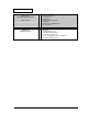
CHAPTER 2 Specifications 2.1 Hardware Specifications This chapter describes specifications of the HDDs. 2.1 Hardware Specifications 2.1.1 Model name and order number Each model has different recording capacities when shipped. Table 2.1 lists the model name and order number. The data format can be changed by reinitializing with the user's system. Table 2.
Specifications 2.1.2 Function specifications Table 2.2 shows the function specifications of the HDDs. Table 2.2 Function specifications Specification Item Formatted capacity/device (*1) Number of disks Number of heads -1 Number of rotations min (rpm) Average latency time Track to Track Seek time (*3) Average (Read/Write) Full stroke MAX3147RC MAX3073RC MAX3036RC 147 GB (*2) 73.5 GB (*2) 36.7 GB (*2) 4 2 1 8 4 2 15,000 ± 0.2 % 2.0 ms 0.2 ms / 0.4 ms 3.3 ms / 3.8 ms 8.0 ms / 9.
2.1 Hardware Specifications The seek time is as follows: Seek time [ms] (*3) Seek Difference [4096 Cyl/div] (*4) The start time is the time from power on or start command to when the HDDs are ready, and the stop time is the time for disks to completely stop from power off or stop command. (*5) This value indicates in idle mode. Power supply at nominal voltage ±1%. 25°C ambient.
Specifications 2.1.3 Environmental specifications Table 2.3 lists environmental and power requirements. Table 2.3 Environmental/Power requirements Specification Item MAX3147RC Operating Temperature (*1) Relative humidity Non-operating –40 to 70 °C Transport (within a week) –40 to 70 °C DE surface temperature at operating 5 to 60 °C Gradient 15 °C/h or less Operating 5 to 95 %RH Non operating 5 to 95 %RH Transport (within a week) 5 to 95 %RH Altitude 0.6 mm (5 to 20Hz) / 9.
2.1 Hardware Specifications (*1) For detail condition, see Section 4.1. (*2) Vibration applied to the drive is measured at near the mounting screw hole on the frame as much as possible. (*3) At random seek write/read and default on retry setting with log sweep vibration. (*4) At power-off state after installation Vibration displacement should be less than 2.5 mm. (*5) Input voltages are specified at the drive connector side, during drive ready state.
Specifications (2) Mean Time To Repair (MTTR) MTTR is the average time taken by a well-trained service mechanic to diagnose and repair a drive malfunction. The drive is designed for a MTTR of 30 minutes or less. (3) Service life The service life under suitable conditions and treatment is as follows. The service life is depending on the environment temperature. Therefore, the user must design the system cabinet so that the average DE surface temperature is as low as possible.
CHAPTER 3 Data Format 3.1 Data Space 3.2 Logical Data Block Addressing 3.3 Defect Management This chapter explains data space definition, logical data block addressing, and defect management on the HDDs. 3.1 Data Space The HDDs manage the entire data storage area divided into the following three data spaces.
Data Format Note: Spare sectors on the last track in each cylinder are not necessarily placed at the end of the track because of a track skew or a cylinder skew. (Details are explained in Subsection 3.1.3) Figure 3.1 Cylinder configuration Apart from the above logical configuration, the HDDs intend to increase the storage capacity by dividing all cylinders into several zones and changing a recording density of each zone.
3.1 Data Space (1) User space The user space is a storage area for user data. The data format on the user space (the length of data block and the number of data blocks) can be specified with the MODE SELECT or MODE SELECT EXTENDED command. The user can also specify the number of logical data blocks to be placed in the user space with the MODE SELECT or MODE SELECT EXTENDED command.
Data Format 3.1.2 Alternate spare area The alternate spare area consists of the last track of each cell in the user space and an alternate cylinder allocated to the last cylinder of each zone. The spare area in each cell is placed at the end of the last track as shown in Figure 3.2. These spare sectors are located in the end of the track logically, not necessarily located at the end physically because of track skew or cylinder skew. (Details are explained on Subsection 3.1.3.
3.1 Data Space 3.1.3 Track format (1) Physical sector allocation Figure 3.4 shows the allocation of the physical sectors in a track. The length in bytes of each physical sector and the number of sectors per track vary depending on the logical data block length. The unused area (G4) exists at the end of the track in formats with most logical data block lengths. The interval of the sector pulse (length of the physical sector) is decided by the HDDs internal free running clock frequency.
Data Format Track skew Head Track skew Head skew Head Leading logical sector in head p+1 Figure 3.5 Track skew/head skew The number of physical sectors (track skew factor and head skew factor) corresponding to the skew time varies depending on the logical data block length because the track skew and the head skew are managed for individual sectors.
3.1 Data Space Each sector on the track consists of the following fields: (1) Gaps (G1, G2, G3) No pattern is written on the gap field. (2) PLO Sync In this field, pattern X'00' is written. (3) Sync Mark (SM1, SM2) In this field, special pattern is written. This special pattern indicates the beginning of the data field. (4) Data field (DATA1-DATA4) User data is stored in the data field of the sector.
Data Format 3.1.5 Format capacity The size of the usable area for storing user data on the HDDs (format capacity) varies according to the logical data block or the size of the spare sector area. Table 3.1 lists examples of the format capacity when the typical logical data block length and the default spare area are used. The following is the general formula to calculate the format capacity.
3.2 Logical Data Block Addressing (1) Block address of user space The logical data block address number is consecutively assigned to all of the data blocks in the user space starting with 0 to the first data block. The HDDs treat sector 0, track 0, cylinder 0 as the first logical data block. The data block is allocated in ascending order of addresses in the following sequence (refer to Figure 3.5): 1) Logical data blocks are assigned in ascending order of sector number in the same track.
Data Format 3.3 Defect Management 3.3.1 Defect list Information of the defect location on the disk is managed by the defect list. The following are defect lists which the HDDs manage. • P list (Primary defect list): This list consists of defect location information available at the disk drive shipment and is recorded in a system space. The defects in this list are permanent, so the INIT must execute the alternate block allocation using this list when initializing the disk.
3.3 Defect Management (1) Alternate block allocation during FORMAT UNIT command execution When the FORMAT UNIT command is specified, the allocation of the alternate block to those defective sectors included in the specified lists (P, G, or D) is continued until all spare sectors in the same cell are used up. When they are used up, unused spare sectors in the alternate cylinder are allocated to the subsequent sectors in the cylinder by means of alternate sector treatment. Figure 3.
Data Format If above errors are detected during FORMAT UNIT command, the HDDs allocate the alternate block(s) to the defective data blocks. Reassign procedure itself is the same as one in REASSIGN BLOCKS command. *1 (2) Certification is permitted when DCRT flag is cleared (DCRT flag=0) in FORMAT UNIT command. The HDDs check all initialized logical data blocks by reading them out after the above alternate block allocation is made to initialize (format) the disk.
3.3 Defect Management (3) Automatic alternate block allocation • Automatic alternate block allocation at read operation If the ARRE flag in the MODE SELECT parameter permits the automatic alternate block allocation, the HDDs automatically execute the alternate block allocation and data duplication on the defective data block detected during the READ or READ EXTENDED command. This allocation method is the same as with the REASSIGN BLOCKS command (alternate sector treatment).
Data Format Type 2 (Reassignment of write fail sector) 1) Commands to be applied WRITE WRITE EXTENDED FORMAT UNIT WRITE at executing WRITE AND VERIFY 2) Application requirements / processing When WRITE/WRITE EXTENDED command detects any Servo error (e.g. Write offtrack error) and cannot be recovered within pre-determined retry number (specified in Mode Parameter). For the sectors around defective Servo, alternate blocks are allocated and the data of this WRITE commands are re-written.
CHAPTER 4 Installation Requirements 4.1 Mounting Requirements 4.2 Power Supply Requirements 4.3 Connection Requirements This chapter describes the environmental, mounting, power supply, and connection requirements. 4.1 Mounting Requirements 4.1.1 Dimensions Figures 4.1 show the dimensions of the HDDs and the location of the mounting screw holes. [Units: mm] Figure 4.
Installation Requirements 4.1.2 Mounting orientations The permissible orientations of the HDDs are shown in Figure 4.2, and the tolerance of the angle is ±5° from the horizontal plane. (a) Horizontal –1 (b) Horizontal –2 (c) Vertical –1 (d) Vertical –2 (e) Upright mounting –1 (f) Upright mounting –2 Direction of gravity Figure 4.
4.1 Mounting Requirements 4.1.3 Notes on mounting Damage Never remove any labels from the drive or deface them in any way. (1) Mounting screw Use No.6-32UNC-2B metric (2) Mounting frame structure Special attention must be given to mount the HDDs as follows. a) Use the frame with an embossed structure, or the like. Mount the HDDs with making a gap of 2.5 mm or more between the HDDs and the frame of the system. b) As shown in Figure 4.
Installation Requirements (3) Limitation of side-mounting Mount the HDDs using the 4 screw holes at the both ends on the both sides as shown in Figure 4.4. Do not use the center hole by itself. In case of using the center hole, it must be used in combination with 2 holes on both ends. (Total 6 screws for 6 holes enclosed) 4 Holes for mounting screw 3 2 Holes for mounting screw 1 ‚ of using a center hole, use it in In case combination with the holes of both ends. Use four holes (No.1 to No.4) to mount.
4.1 Mounting Requirements (5) Environmental temperature Temperature condition at installed in a cabinet is indicated with ambient temperature measured 30 mm from the disk drive. At designing the system cabinet, consider following points. • Make a suitable air flow so that the DE surface temperature never exceed 60°C. • Cool the PCA side especially with air circulation inside the cabinet. Confirm the cooling effect by measuring the surface temperature of specific ICs and the DE.
Installation Requirements (6) Service clearance area The service clearance area, or the sides which must allow access to the HDDs for installation or maintenance, is shown in Figure 4.6. [Surface X] • Holes for mounting screw (Both side) [Surface Y] • Interface connection [Surface Z] • Holes for mounting screw Figure 4.6 (7) Service clearance area External magnetic field The drive should not be installed near the ferromagnetic body like a speaker to avoid the influence of the external magnetic field.
4.2 Power Supply Requirements 4.2 Power Supply Requirements (1) Allowable input voltage and current The power supply input voltage measured at the power supply connector pin of the HDDs (receiving end) must satisfy the requirement given in Subsection 2.1.3. (For other requirements, see Items (4) and (5) below.) (2) Current waveform (reference) Figure 4.7 shows the spin-up current waveform of +12V DC. Current (500mA/div) Time (2 sec/div) Time (2 sec/div) Figure 4.
Installation Requirements (5) Noise filter To eliminate AC line noise, a noise filter should be installed at the AC input terminal on the HDD power supply unit. The specification of this noise filter is as follows: • Attenuation: 40 dB or more at 10 MHz • Circuit construction: T-configuration as shown in Figure 4.8 is recommended. Figure 4.8 4.3 Connection Requirements 4.3.1 Connector location AC noise filter Figure 4.9 shows a location of the interface connector.
4.3 Connection Requirements 4.3.2 Interface connector Figure 4.10 shows the SAS type interface connector (SAS plug) overview. Table 4.2 lists the signal allocation of the SAS plug on the HDDs. S1 S7 P1 P15 S14 S8 Figure 4.
Installation Requirements Table 4.2 Pin No.
4.3 Connection Requirements 4.3.3 Ready LED output signal Figure 4.11 shows a recommended circuit for external LED connection to Ready LED output signal. Figure 4.11 Recommended external circuit for Ready LED output Either +3.3 V or +5 V can be used for external power supply for LED (Vcc). Current limiting resister (R) value need to be adjusted depend on the Vcc voltage. For +3.3 V Vcc voltage, recommended resistance is 220 Ω. For +5 V Vcc voltage, recommended resistance is 330 Ω.
This page is intentionally left blank.
CHAPTER 5 Installation 5.1 Notes on Handling Drives 5.2 Setting 5.3 Mounting Drives 5.4 Checking Operation after Installation and Preparing the HDDs for Use 5.5 Dismounting Drives 5.6 Spare Disk Drive This chapter describes the notes on handling drives, setting, mounting drives, confirming drive operations after installation and preparation for use, and dismounting drives. 5.1 Notes on Handling Drives The items listed in the specifications in Table 2.3 must be strictly observed.
Installation (2) Unpackaging a) Use a flat work area. Check that the "This Side Up" sign side is up. Handle the package on soft material such as a rubber mat, not on hard material such as a desk. b) Be careful not to give excess pressure to the internal unit when removing cushions. c) Be careful not to give excess pressure to the PCA and interface connector when removing the drive from the Fcell. d) Do not remove any labels from the drive. Never open the DE for any reason.
5.2 Setting 5.2 Setting 5.2.1 Port Address Every device that uses the SAS interface has a unique SAS address, and commands use an SAS address to identify each device for I/O operations. Every HDD is assigned a unique SAS address before shipment from the factory, so setting of an address is not required before the HDDs are used. 5.3 Mounting Drives 5.3.
Installation 5.4 Checking Operation after Installation and Preparing the HDDs for Use 5.4.1 Checking initial operation The procedure for verifying operation after power-on is explained below. (1) Initial diagnosis at the time of power-on: a) When the HDDs are turned on, the Active LED blinks and the HDDs perform the initial selfdiagnosis (controller hardware diagnosis).
5.4 Checking Operation after Installation and Preparing the HDDs for Use c) Issue the REQUEST SENSE command to collect sense data. When sense data has been collected successfully, perform an analysis to check for recoverable errors, and retry operations for recovery from any such errors. (5) Checking at abnormal end a) When sense data can be obtained, analyze the sense data and retry recovery for a recoverable error.
Installation (2) FORMAT UNIT command Initialize entire recording surface of the disk with the FORMAT UNIT command. The FORMAT UNIT command initializes entire surface of the disk using the P lists, verifies data blocks after initialization, and allocates an alternate block for a defect block detected with verification. With initialization, the value "00" is written into all bytes of all logical data blocks.
5.4 Checking Operation after Installation and Preparing the HDDs for Use 5.4.3 Setting parameters The user can specify the optimal operation mode for the user system environments by setting the following parameters with the MODE SELECT or MODE SELECT EXTENDED command: • • • Error recovery parameter Caching parameter Control mode parameter With the MODE SELECT or MODE SELECT EXTENDED command, specify 1 for the "SP" bit on CDB to save the specified parameter value on the disk.
Installation (1) Error recovery parameters The following parameters are used to control operations such as HDD internal error recovery: a.
5.4 Checking Operation after Installation and Preparing the HDDs for Use (2) Caching parameters The following parameters are used to optimize HDD Read-Ahead caching operations under the system environments. Refer to Chapter 3 “Data Buffer Management” of the Interface Specifications for further details.
Installation 5.5 Dismounting Drives Since the method and procedure for dismounting the disk drive for replacement of the drive, etc. depends on the locker structure of the system, etc., the work procedure must be determined in consideration of the requirements specific to the system. This section describes the general procedure and notes on dismounting the drive. Damage 1. When dismounting the drive which is mounted on the system while power is supplied to it.
CHAPTER 6 Diagnostics and Maintenance 6.1 Diagnostics 6.2 Maintenance Information 6.3 Operation Check 6.4 Troubleshooting Procedures This chapter describes diagnostics and maintenance information. 6.1 Diagnostics 6.1.1 Self-diagnostics The HDDs have the following self-diagnostic function. This function checks the basic operations of the HDDs. • • Initial self-diagnostics Online self-diagnostics (SEND DIAGNOSTIC command) Table 6.
Diagnostics and Maintenance Brief test contents of self-diagnostics are as follows. a. Hardware function test This test checks the basic operation of the controller section, and contains following test. • • • • RAM (microcode is stored) Peripheral circuits of microprocessor (MPU) Memory (RAM) Data buffer b. Seek test This test checks the positioning operation of the disk drive using several seek modes (2 points seek, 1 position sequential seek, etc.).
6.1 Diagnostics (2) Online self-diagnostics (SEND DIAGNOSTIC command) The INIT can make the HDDs execute self-diagnostics by issuing the SEND DIAGNOSTIC command. The INIT specifies the execution of self-diagnostics by setting 1 for the SelfTest bit on the CDB in the SEND DIAGNOSTIC command and specifies the test contents with the UnitOfl bit. When the UnitOfl bit on the CDB is set to 0, the HDDs execute the hardware function test only once.
Diagnostics and Maintenance b) When an error is detected in the hardware function test, the HDDs post the CHECK CONDITION status for all I/O operation request except the REQUEST SENSE command. The error status is not cleared even if the error information (sense data) is read. Only when the power is turned off or re-turned on, the status can be cleared. When this status is cleared, the HDDs execute the initial self-diagnostics again (see item (1)). Refer to Subsection 4.4.
6.2 Maintenance Information 6.2 Maintenance Information See Section 5.1 for notes on packing and handling when returning the disk drive. Data loss Save data stored on the disk drive to other media before requesting repair. Fujitsu does not assume responsibility if data is destroyed during servicing or repair. 6.2.1 Precautions Take the following precautions to prevent injury during maintenance and troubleshooting: High temperature To prevent injury, never touch the drive while it is hot.
Diagnostics and Maintenance 6.2.2 Maintenance requirements (1) Preventive maintenance Preventive maintenance is not required. (2) Service life See "(3) Service life," in Section 2.1.5. (3) Parts that can be replaced in the field The PCA cannot be replaced in the field. The DE cannot be replaced in the field. (4) Service system and repairs Fujitsu has the service system and repair facility for the disk drive.
6.2 Maintenance Information 6.2.3 Maintenance levels If a disk drive is faulty, replace the whole disk drive since repair requires special tools and environment. This section explains the two maintenance levels. (1) (2) 6.2.4 Field maintenance (disk drive replacement) • This replacement is done at the user's site. • Replacement uses standard tools. • Replacement is usually done by the user, retail dealer, distributor, or OEM engineer.
Diagnostics and Maintenance (1) Indicating revision number at factory shipment When the disk drive is shipped from the factory, the revision number is indicated by deleting numbers in the corresponding letter line up to the corresponding number with = (see Figure 6.2).
6.2 Maintenance Information 6.2.6 Tests This disk drive can be tested in the following ways: • • • Initial seek operation check (See Subsection 6.3.1) Operation test (See Subsection 6.3.2) Diagnostic test (See Subsection 6.3.3) Figure 6.3 shows the flow of these tests. Start Start self-test by turning the power on No Test results OK? Check host system (Table 6.
Diagnostics and Maintenance 6.3 Operation Check 6.3.1 Initial seek operation check If an error is detected during initialization by the initial seek operation check routine at power-on, the spindle motor of the disk drive stops, and then the disk drive becomes unusable. For an explanation of the operation check before the initial seek, refer to the Section 5.4. 6.3.
6.4 Troubleshooting Procedures 6.4 Troubleshooting Procedures 6.4.1 Outline of troubleshooting procedures This section explains the troubleshooting procedures for disk drive errors. Depending on the maintenance level, analyze the error to detect a possibly faulty part (disk drive, or disk drive part). Full-scale troubleshooting is usually required if the error cause is not known. If the error cause is clear (e.g.
Diagnostics and Maintenance Table 6.2 Item DC power level System-level field troubleshooting Recommended work Check that the DC voltage is within the specified range (±5%). For +5V DC, measure the voltage between pin P8 (+5V) of the interface connector and the nearest PCA mounting screw (GND) from the interface connector, and confirm the value is from 4.75 to 5.25 VDC.
6.4 Troubleshooting Procedures 6.4.3 Troubleshooting at the repair site For maintenance at this level, we recommend additional testing of the disk drive and signal checking. The sense data posted from the HDDs help with troubleshooting. This sense data makes the error type clear (functional, mechanical, or electrical error). Chapter 7 error analysis by sense data, and gives supplementary information on finding the error cause (faulty part). Table 6.3 lists how to detect a faulty disk drive subassembly.
Diagnostics and Maintenance 6.4.4 Troubleshooting with parts replacement in the factory This manual does not cover troubleshooting at the factory level. 6.4.5 Finding possibly faulty parts Finding possibly faulty parts in the field was explained in Subsection 6.4.2. This manual does not cover finding possibly faulty parts at the factory level.
CHAPTER 7 Error Analysis 7.1 Error Analysis Information Collection 7.2 Sense Data Analysis This chapter explains in detail how sense data collected from a disk drive is used for troubleshooting. Sense data reflects an error in the disk drive, and helps with troubleshooting. A sense key, additional sense code, and additional sense code qualifier, taken from various sense data are repeated. Also in this chapter, troubleshooting is performed using these three codes.
Error Analysis Bit 7 Byte 0 6 5 Valid 4 3 2 1 X‘70’ or X‘71’ (error code) 1 X‘00’ 2 0 0 3 [MSB] ILI 4 0 Sense key Information 5 6 [LSB] 7 Basic information 8 0 X‘28’ (additional sense data length) [MSB] 9 Command-specific information 10 11 [LSB] 12 Additional sense code 13 Additional sense code qualifier 14 X‘00’ 15 SKSV 16 Sense key-specific information 17 18 0 0 0 19 Additional information Port 0 0 0 0 CDB operation code 20 Detail information 47 ILI: MS
7.2 Sense Data Analysis 7.2 Sense Data Analysis 7.2.1 Error information indicated with sense data Subsection 7.2.2 onwards explain troubleshooting using sense data. For details of the following sense data, refer to Chapter 5 “Sense Data Error Recovery Methods” of the Interface Specifications. Table 7.1 lists the definition of sense data. For details of sense data, refer to the Interface Specifications. Table 7.
Error Analysis 7.2.2 Sense data (3-0C-03), (4-32-01), (4-40-xx), (4-C4-xx), and (4-44-xx) Sense data (3-0C-03), (4-32-01), (4-40-xx), (4-C4-xx), and (4-44-xx) indicate one of the following: • A target sector could not be detected using the sector counter. • A seek process overran the specified time. • A write to a disk terminated abnormally. • An error occurred in power-on self-diagnosis. • A drive error occurred. The symptoms above are generally caused by an error in a PCA or DE. 7.2.
Glossary Additional Sense Code This is a 1-byte code displayed in the sense data and is information which specifies the type of error that was detected. CCS Common Command Set This is the standard form of SCSI logical specifications stipulated by the operations subcommittee of the American National Standards Institute (ANSI) which stipulates functions which a direct access device (magnetic disk, etc.) should support.
Glossary Target (TARG) This is the SAS device that executes the input/output operations initiated by the initiator (INIT). In this manual, target is abbreviated "TARG.
Acronyms and Abbreviations A AC ACK AEN ALT ARRE Alternating Current ACKnowledge primitive Asynchoronous Event Notification ALTernated (block) Automatic Read Reallocation Enabled ASCII American Standard Code for Information Interchange ASG ASiGned block AWG American Wire Gauge AWRE Automatic Write Reallocation Enabled E ECC EER EVPD F FG FIFO FmtData FOV FUA G G list Target Certification list Common command set Command descriptor block Customer Engineer Complete List Cyclic Redundancy Check CYLinder D
Acronyms and Abbreviations M MPU MR MS MicroProcessor Unit Magnetro Resistive Multiple Select T TB TPI TRM N NACK Negative ACKnowledge primitive U UnitOfl Unit Offline O OEM Original Equipment Manufacturer Transfer Block Tracks Per Inch TeRMinator V VCM VPD VU Voice Coil Motor Vital Product Data Vendor Unique P P list Primary defect list P/N Parts/Number PBdata Physical Block data PC board Printed Circuit board PCA Printed Circuit Assembly PER Post ERror PF Page Format PLO Sync Phase Lock Oscilla
Index A actuator ........................................................... 1-5 additional error recovery parameter ............... 5-8 allowable input voltage and current................ 4-7 alternate area................................................... 3-9 alternate block allocation.............................. 3-10 alternate block allocation by REASSIGN BLOCKS command ................................ 3-12 alternate block allocation during FORMAT UNIT command execution ....
Index high-speed data transfer .................................. 1-2 I indicating revision number at factory shipment .................................................... 6-8 initial diagnosis at time of power-on .............. 5-4 initial seek operation check........................... 6-10 initial self-diagnostic....................................... 6-2 installation....................................................... 5-1 installation requirement ..................................
Index sense key, additional sense code, and additional sense code qualifier.................. 7-1 sequential starting of spindle motor................ 4-7 service clearance area ..................................... 4-6 service life ............................................... 2-6, 6-6 service system and repair................................ 6-6 setting ............................................................. 5-3 setting parameter ............................................ 5-7 spare disk drive...
This page is intentionally left blank.
Comment Form We would appreciate your comments and suggestions regarding this manual. Manual code C141-E237-01EN Manual name MAX3147RC, MAX3073RC, MAX3036RC HARD DISK DRIVES PRODUCT/MAINTENANCE MANUAL Please mark each item: E(Excellent), G(Good), F(Fair), P(Poor). General appearance Technical level Organization Clarity Accuracy ( ( ( ( ( ) ) ) ) ) Illustration Glossary Acronyms & Abbreviations Index ( ( ( ( ) ) ) ) Comments & Suggestions List any errors or suggestions for improvement.
This page is intentionally left blank.