FUJITSU SEMICONDUCTOR CM71-10106-1E CONTROLLER MANUAL FR30 32-Bit Microcontroller MB91F109 Hardware Manual
FR30 32-Bit Microcontroller MB91F109 Hardware Manual FUJITSU LIMITED
PREFACE ■ Objectives and Intended Reader The MB91F109 has been developed as one of the "32-bit single-chip microcontroller FR30 series" products that use new RISC architecture CPUs as their cores. It has optimal specifications for embedding applications that require high CPU processing power. This manual explains the functions and operations of the MB91F109 for the engineers who actually develop products using the MB91F109. Read this manual thoroughly.
■ Organization of This Manual This manual consists of 16 chapters and an appendix. Chapter 1 Overview Chapter 1 provides basic general information on the MB91F109, including its characteristics, a block diagram, and function overview. Chapter 2 CPU Chapter 2 provides basic information on the FR series CPU core functions including the architecture, specifications, and instructions.
Chapter 14 PWM Timer Chapter 14 provides an overview of the PWM timer, explains the register configuration and functions, and operations of the PWM timer. Chapter 15 DMAC Chapter 15 provides an overview of the DMAC, explains the register configuration and functions, and operations of the DMAC. Chapter 16 Flash Memory Chapter 16 explains the flash memory functions and operations. The chapter provides information on using the flash memory from the FR CPU.
1. The contents of this document are subject to change without notice. Customers are advised to consult with FUJITSU sales representatives before ordering. 2. The information and circuit diagrams in this document are presented as examples of semiconductor device applications, and are not intended to be incorporated in devices for actual use.
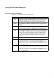
How to Read This Manual ■ Description Format of this Manual Major terms used in this manual are explained below: Term Meaning I-BUS 16-bit wide bus used for internal instructions. Since the FR series uses an internal Harvard architecture, independent buses are used for instructions and data. A bus converter is connected to the I-BUS. D-BUS Internal 32-bit wide data bus. Internal resources are connected to the D-BUS. C-BUS Internal multiplex bus.
vi
CONTENTS CHAPTER 1 1.1 1.2 1.3 1.4 1.5 1.6 1.7 1.8 OVERVIEW ................................................................................................... 1 MB91F109 Characteristics .................................................................................................................... 2 General Block Diagram of MB91F109 ................................................................................................... 6 Outside Dimensions ................................................
3.9 Gear Function ..................................................................................................................................... 87 3.10 Standby Mode (Low Power Consumption Mechanism) ...................................................................... 90 3.10.1 Stop State ...................................................................................................................................... 92 3.10.2 Sleep State ........................................................
4.17.17 Hyper DRAM Interface: Read ....................................................................................................... 188 4.17.18 Hyper DRAM Interface: Write ....................................................................................................... 189 4.17.19 Hyper DRAM Interface ................................................................................................................. 190 4.17.20 DRAM Refresh .........................................................
10.5 10.6 10.7 10.8 10.9 10.10 10.11 Serial Status Register (SSR) ............................................................................................................ UART Operation ............................................................................................................................... Asynchronous (Start-Stop) Mode ...................................................................................................... CLK Synchronous Mode ......................................
.5 Descriptor Register in RAM ............................................................................................................... 332 15.6 DMAC Transfer Modes ...................................................................................................................... 335 15.7 Output of Transfer Request Acknowledgment and Transfer End signals .......................................... 338 15.8 Notes on DMAC ..............................................................................
FIGURES Figure 1.2-1 General Block Diagram of MB91F109 ........................................................................................ 6 Figure 1.3-1 Outside Dimensions of FPT-100P-M06 ...................................................................................... 7 Figure 1.3-2 Outside Dimensions of FPT-100P-M05 ...................................................................................... 8 Figure 1.3-3 Outside Dimensions of BGA-112P-M01 ....................................
Figure 3.15-1 Example of PLL Clock Setting ................................................................................................. 108 Figure 3.15-2 Clock System Reference Diagram .......................................................................................... 109 Figure 4.1-1 Bus Interface Registers ........................................................................................................... 113 Figure 4.1-2 Bus Interface Block Diagram ..............................
Figure 4.17-12 Example 5 of Write Cycle Timing Chart .................................................................................. 169 Figure 4.17-13 Example of Read and Write Combination Cycle Timing Chart ............................................... 170 Figure 4.17-14 Example of Automatic Wait Cycle Timing Chart ..................................................................... 171 Figure 4.17-15 Example of External Wait Cycle Timing Chart .......................................................
Figure 7.1-1 Delayed Interrupt Module Register .......................................................................................... 220 Figure 7.1-2 Delayed Interrupt Module Block Diagram ................................................................................ 220 Figure 8.1-1 Interrupt Controller Registers (1/2) .......................................................................................... 225 Figure 8.1-2 Interrupt Controller Registers (2/2) ...............................
Figure 14.10-1 One-Shot Operation Timing Chart (Trigger Restart Disabled) ................................................ 318 Figure 14.10-2 One-Shot Operation Timing Chart (Trigger Restart Enabled) ................................................ 318 Figure 14.11-1 Causes of Interrupts and Their Timing (PWM Output: Normal Polarity) ................................ 319 Figure 14.12-1 Example of Keeping PWM Output at a Lower Level ...............................................................
TABLES Table 1.4-1 FBGA Package Pin Names ....................................................................................................... 13 Table 1.5-1 Pin Functions (1/5) .................................................................................................................... 14 Table 1.5-2 Pin Functions (2/5) .................................................................................................................... 15 Table 1.5-3 Pin Functions (3/5) ...................
Table 8.3-1 Correspondences between the Interrupt Level Setting Bits and Interrupt Levels ................... 229 Table 8.5-1 Relationships among Interrupt Causes, Numbers, and Levels (1/2) ...................................... 231 Table 8.5-2 Relationships among Interrupt Causes, Numbers, and Levels (2/2) ...................................... 232 Table 8.7-1 Settings for the Interrupt Levels for which a Hold Request Cancel Request is Issued ........... 235 Table 10.
Table A-4 I/O Map (4/6) ........................................................................................................................... 375 Table A-5 I/O Map (5/6) ........................................................................................................................... 376 Table A-6 I/O Map .................................................................................................................................... 377 Table B-1 Interrupt Vectors (1/2) ............
xx
CHAPTER 1 OVERVIEW This chapter provides basic general information on the MB91F109, including its characteristics, block diagram, and function overview. 1.1 MB91F109 Characteristics 1.2 General Block Diagram of MB91F109 1.3 Outside Dimensions 1.4 Pin Arrangement Diagrams 1.5 Pin Functions 1.6 I/O Circuit Format 1.7 Memory Address Space 1.
CHAPTER 1 OVERVIEW 1.1 MB91F109 Characteristics The MB91F109 is a standard single-chip microcontroller using a 32-bit RISC CPU (FR30 series) as its core. It contains various I/O resources and bus control mechanisms for embedded control applications that require high-speed CPU processing. This microcontroller contains 254-kilobyte flash ROM and 4-kilobyte RAM.
1.1 MB91F109 Characteristics • Automatic wait cycle: Any number of cycles (0 to 7) can be set for each area. • Unused data and address terminals can be used as I/O ports. • Support for little endian mode (selecting one of areas 1 to 5) ❍ DRAM interface • 2-bank independent control (areas 4 and 5) • Double CAS DRAM (normal DRAM interface), single CAS DRAM, and hyper DRAM • Basic bus cycle: Five cycles in normal mode. Two-cycle access is enabled in high-speed page mode.
CHAPTER 1 OVERVIEW conversion • Starting: Selectable from software, external trigger, and internal timer ❍ Reload timer • 16-bit timer: Three channels • Internal clock: 2-clock cycle resolution.
1.
CHAPTER 1 OVERVIEW 1.2 General Block Diagram of MB91F109 Figure 1.2.1 is a general MB91F109 block diagram. ■ General Block Diagram of MB91F109 Figure 1.
1.3 Outside Dimensions 1.3 Outside Dimensions Figures 1.3.1 to 1.3.3 show the outside dimensions of the MB91F109. ■ Outside Dimensions (QFP-100) Figure 1.3-1 Outside Dimensions of FPT-100P-M06 EIAJ code :* Lead pitch Plastic QFP with 100 pins Package width x length Lead shape Sealing Flat terminal section length QFP100-P-1420-4 0.65 mm 14 x 20 mm Gull wing Plastic mold 0.80 mm (FPT-100P-M06) Plastic QFP with 100 pins (F PT -100P -M06 ) 3.35(.132)MAX (Mounting height) 0.05(.
CHAPTER 1 OVERVIEW ■ Outside Dimensions (LQFP-100) Figure 1.3-2 Outside Dimensions of FPT-100P-M05 EIAJ code: * QFP100-P-1414-1 0.50 mm Lead pitch Plastic LQFP with 100 pins Package width x length 14 x 14 mm Lead shape Gull wing Plastic mold Sealing (FPT-100P-M05) Plastic LQFP with 100 pins (FPT-100P-M05) 16.00 0.20(.630 .008)SQ 75 1.50 .059 51 14.00 0.10(.551 .004)SQ 76 +0.20 -0.10 +.008 -.004 (Mouting height) 50 12.00 (.472) REF 15.00 (.591) NOM Details of "A" part 0.15(.
1.3 Outside Dimensions ■ Outside Dimensions (FBGA-112) Figure 1.3-3 Outside Dimensions of BGA-112P-M01 Ball pitch 0.80 mm Ball matrix 11 Package width x length 10.00 × 10.00 mm Plastic FBGA with 112 pins Sealing Plastic mold Mount height 1.45 mm MAX Ball size 0.45 (BGA-112P-M01) Plastic FBGA with 112 pins (BGA-112P-M01) 10.00 0.10(.394 .004)SQ Note: The actual corner shape may differ from the drawing. +0.20 +.008 8.00(.314)REF 1.25 -0.10 .049 -.004 (Mounting height) 0.38 0.10(.015 .
CHAPTER 1 OVERVIEW 1.4 Pin Arrangement Diagrams Figures 1.4.1 to 1.4.3 show the pin arrangements of the MB91F109. ■ Pin Arrangements (QFP-100) 100 99 98 97 96 95 94 93 92 91 90 89 88 87 86 85 84 83 82 81 CS0L/PB1 RAS0/PB0 INT0/PE0 INT1/PE1 VCC X0 X1 VSS INT2/PE2/SC1 INT3/PE3/SC2 DREQ0/PE4 DREQ1/PE5 DACK0/PE6 DACK1/PE7 PF7/OCPA0/ATGX SO2/PF6/OCPA2 SI2/PF5/OCPA1 SO1/PF4/TRG3 SI1/PF3/TRG2 SC0/PF2/OCPA3 Figure 1.
1.
CHAPTER 1 OVERVIEW ■ Pin Arrangements (FBGA-112) Figure 1.4-3 FBGA-112 Pin Arrangements 11 10 9 8 7 TOP VIEW 6 5 4 3 2 1 INDEX A B C D E F G H J K Table 1.4.1 shows the cross-references of the FBGA package pin names.
1.4 Pin Arrangement Diagrams Table 1.4-1 FBGA Package Pin Names BALL-No. PIN-NAME BALL-No. PIN-NAME BALL-No. H9 H10 H11 J1 J2 PIN-NAME A14/ P56 A13/ P55 N.C. RDX/ P83 WR0X/ P84 A1 A2 A3 A4 A5 N.C RAS1/ PB4/ EOP2 CS0L/ PB1 INT1/ PE1 X1 D6 D7 D8 D9 D10 VCC DREQ0/ PE4 OCPA0/ PF7/ ATGX AN2 AVRH A6 A7 A8 A9 A10 INT3/ SC2/ PE3 DACK1/ PE7 SI2/ OCPA1/ PF5 SC0/ OCPA3/ PF2 SI0/ TRG0/ PF0 D11 E1 E2 E3 E4 AVCC CS1X/ PA1 CS0X/ PA0 NMIX VCC J3 J4 J5 J6 J7 D21/ P25 D24/ P30 N.C.
CHAPTER 1 OVERVIEW 1.5 Pin Functions Tables 1.5.1 to 1.5.5 lists the MB91F109 pin functions. The numbers shown in the tables has nothing to do with the package pin numbers. Since pins have different pin numbers among QFP, LQFP, and FBGA, see Section 1.4, "Pin Arrangement Diagrams." ■Pin Functions Table 1.5-1 Pin Functions (1/5) NO. Pin name I/O circuit format 1 2 3 4 5 6 7 8 D16/P20 D17/P21 D18/P22 D19/P23 D20/P24 D21/P25 D22/P26 D23/P27 E Bits 16 to 23 of external data bus.
1.5 Pin Functions Table 1.5-1 Pin Functions (1/5) NO. Pin name I/O circuit format Function 33 34 35 36 37 38 39 40 A16/P60 A17/P61 A18/P62 A19/P63 A20/P64 A21/P65 A22/P66 A23/P67 F Bits 16 to 23 of external address bus. When these pins are not used for the address bus, they can be used as general-purpose I/O ports (P60 to P67). Table 1.5-2 Pin Functions (2/5) NO. Pin name I/O circuit format Function 41 A24/P70/EOP0 F Bit 24 of external address bus.
CHAPTER 1 OVERVIEW Table 1.5-2 Pin Functions (2/5) NO. Pin name I/O circuit format 47 WR1X/P85 F Function 16-bit bus width 8-bit bus width Single-chip mode D15 to D08 WR0X WR0X (can be used as a port) D07 to D00 WR1X (can be used as a port) (can be used as a port) Note: WR1X is Hi-Z while it is in reset state. When it is used as a 16-bit bus, attach a pull-up resistor to the outside. [P84 or P85] When WR0X or WR1X is not used, the pin can be used as a general-purpose I/O port.
1.5 Pin Functions Table 1.5-3 Pin Functions (3/5) NO.
CHAPTER 1 OVERVIEW Table 1.5-3 Pin Functions (3/5) NO. Pin name I/O circuit format 73 INT2/SC1/PE2 F Function [INT2] Input of external interrupt request. This input is used from time to time while the corresponding external interrupt is enabled. Therefore, it is needed to stop output by other functions except when such output is performed intentionally. [SC1] UART1 clock I/O. Clock output can be used when UART1 clock output is enabled. [PE2] General-purpose I/O port.
1.5 Pin Functions Table 1.5-4 Pin Functions (4/5) NO. Pin name I/O circuit format 78 DACK1/PE7 F Function [DACK1] Output of DMAC external transfer request acceptance (ch1). This function is valid when the output of DMAC transfer request acceptance is enabled. [PE7] General-purpose I/O port. This function is valid when the output of DMAC transfer request acceptance or DACK1 output is disabled.
CHAPTER 1 OVERVIEW Table 1.5-4 Pin Functions (4/5) NO. Pin name I/O circuit format 83 SO1/TRG3/PF4 F Function [SO1] UART1 data output. This function is valid when UART1 data output is enabled. [TRG3] External trigger input of PWM timer. This function is valid when PF4 and UART1 data output is disabled. [PF4] General-purpose I/O port. This function is valid when UART1 data output is disabled. Table 1.5-5 Pin Functions (5/5) NO.
1.5 Pin Functions Table 1.5-5 Pin Functions (5/5) NO. Pin name I/O circuit format Function 92 AVRH - Reference voltage of A/D converter (high potential side). Always turn the pin on or off while the voltage equal to AVRH or higher is applied to VCC. 93 AVSS/AVRL - A/D converter VSS power supply and reference voltage (low potential side) 94 to 96 VCC - Digital circuit power supply. Be sure to connect the power supply to every VCC pin.
CHAPTER 1 OVERVIEW 1.6 I/O Circuit Format Tables 1.6.1 and 1.6.2 shows I/O circuit formats. ■ I/O Circuit Format Table 1.
1.6 I/O Circuit Format Table 1.6-1 I/O circuit format (1/2) Classification Circuit format Remarks D • • CMOS level hysteresis input No standby control P-channel transistor N-channel transistor Diffused resistor Digital input CMOS Table 1.
CHAPTER 1 OVERVIEW 1.7 Memory Address Space The logical address space of the FR series consists of 4 gigabytes (232 addresses) and the CPU accesses them linearly. ■ Memory map Figure 1.7.1 shows the memory address space of the MB91F109. Figure 1.7-1 MB91F109 Memory Map External-ROM external-bus mode Internal-ROM external-bus mode Single-chip mode 0000 0000H I/O I/O I/O I/O I/O I/O Direct addressing area 0000 0400H I/O map (See Appendix A.
1.7 Memory Address Space ❍ Direct addressing area The following area in the address space is used for I/O. This area is called the direct addressing area. The addresses in this area can be directly specified for instruction operands.
CHAPTER 1 OVERVIEW 1.8 Handling of Devices This section provides notes on using devices. ■ Device Handling ❍ Latchup prevention If voltage higher than Vcc or lower than Vss is applied to a CMOS IC input or output pin or if voltage exceeding the rating is applied between Vcc and Vss, latchup may be caused. Latchup rapidly increases supply current and may cause thermal damage to the device. To prevent such damage, do not to let voltage exceed the maximum rated voltage.
1.8 Handling of Devices Figure 1.8-2 Example of Using an External Clock (Possible at 12.5 MHz or Lower) X0 OPEN X1 MB91F109 ❍ Connection of power pins (Vcc and Vss) When two or more Vcc or Vss pins are used, the device is designed so that the pins, which should be at the same potential, are connected to one another inside the device to prevent a malfunction such as a latchup.
CHAPTER 1 OVERVIEW ❍ Initialization by power-on reset Devices contain registers that are initialized only by power-on reset. To initialize these registers, turn the power off and turn it on again to execute power-on resetting. ❍ Recovery from sleep or stopped state To recover from the sleep or stopped state that has been entered from a program in C-bus RAM, do not use an interrupt but execute resetting.
CHAPTER 2 CPU This chapter provides basic information on the FR series CPU core functions including the architecture, specifications, and instructions. 2.1 CPU Architecture 2.2 Internal Architecture 2.3 Programming Model 2.4 Data Structure 2.5 Word Alignment 2.6 Memory Map 2.7 Instruction Overview 2.8 EIT (Exception, Interrupt, and Trap) 2.9 Reset Sequence 2.
CHAPTER 2 CPU 2.1 CPU Architecture The FR30 CPU is a high performance core that uses the RISC architecture and supports advanced functional instructions geared to embedding applications.
2.2 Internal Architecture 2.2 Internal Architecture The FR CPU uses the Harvard architecture in which the instruction bus and data bus are independent of each other. The "32 bits <--> 16 bits" bus converter is connected to the data bus (D-BUS) to implement the interface between the CPU and peripheral resources. The "Harvard <--> Princeton" bus converter is connected to both I-BUS and D-BUS to implement the interface between the CPU and bus controller. ■ Internal Architecture Figure 2.2.
CHAPTER 2 CPU Figure 2.2-2 Instruction Pipeline CLK Instruction 1 WB Instruction 2 MA WB Instruction 3 EX MA WB Instruction 4 ID EX MA WB Instruction 5 IF ID EX MA WB IF ID EX MA Instruction 6 WB Instructions are always executed in order. That is, instruction A that is put into the pipeline before instruction B always reaches the write back stage before instruction B. Instructions are normally executed at a rate of one instruction per cycle.
2.3 Programming Model 2.3 Programming Model This section explains the CPU registers that are essential for programming. The CPU registers are classified into the following two groups: • General-purpose registers • Special registers ■ General-Purpose Registers Figure 2.3.1 shows the configuration of general-purpose registers. Figure 2.
CHAPTER 2 CPU Figure 2.
2.3 Programming Model 2.3.1 General-Purpose Registers Registers R0 to R15 are general-purpose registers. They are used as accumulators for various types of operation or memory access pointers. ■ General-Purpose Registers Figure 2.3.3 shows the configuration of general-purpose registers. Figure 2.
CHAPTER 2 CPU 2.3.2 Special Registers The special registers are used for special purposes. They are the program counter (PC), program status (PS), table base register (TBR), return pointer (RP), system stack pointer (SSP), user stack pointer (USP), and multiplication/division result register (MDH/MDL). ■ Special Registers Figure 2.3.4 shows the configuration of special registers. Figure 2.
2.3 Programming Model ❍ Program status (PS) The program status register holds the program status in three parts, CCR, SCR, and ILM. See Section 2.3.3 for more information. The undefined bits are all reserved. When the register is read, 0 is always read from these bits. No data can be written to this register. ❍ Table base register (TBR) The table base register holds the first address of the vector table used for EIT processing. The initial value after resetting is 000FFC00H.
CHAPTER 2 CPU [Division] When calculation begins, a dividend is stored in the MDL.
2.3 Programming Model 2.3.3 Program Status Register (PS) The program status register holds the program status in three parts, ILM, SCR, and CCR. The undefined bits are all reserved. When the register is read, 0 is always read from these bits. No data can be written to this register.
CHAPTER 2 CPU [bit 3] N: Negative flag This bit indicates a sign applicable when the operation result is assumed to be an integer that is represented in two’s complement. 0: Indicates that the operation result is a positive value. 1: Indicates that the operation result is a negative value. The initial value after resetting is undefined. [bit 2] Z: Zero flag This bit indicates whether the operation result is 0. 0: Indicates that the operation result is a value other than 0.
2.3 Programming Model [bit 8] T: Step-trace-trap flag This flag specifies whether to enable step-trace-trap. 0: Disables step-trace-trap. 1: Enables step-trace-trap. Setting the bit to 1 inhibits all user NMIs and user interrupts. The flag is cleared to 0 by resetting. The step-trace-trap function is used by an emulator. It cannot be used in user programs while it is used by the emulator.
CHAPTER 2 CPU 2.4 Data Structure FR-series data is mapped as follows: • Bit ordering: Little endian • Byte ordering: Big endian ■ Bit Ordering The FR series uses little endian for bit ordering. Figure 2.4.1 shows data mapping in bit ordering mode. Figure 2.4-1 Data Mapping in Bit Ordering Mode bit 31 29 30 27 28 25 26 23 24 21 22 19 20 17 18 15 16 13 14 11 12 9 10 7 8 5 6 3 4 1 2 0 LSB MSB ■ Byte Ordering The FR series uses big endian for byte ordering. Figure 2.4.
2.5 Word Alignment 2.5 Word Alignment Since instructions and data are accessed in bytes, mapping addresses vary depending on instruction length or data width. ■ Program Access A program running in the FR series must be placed at an address consisting of a multiple of two. Bit 0 of the program counter (PC) is set to 0 when the PC is updated according to instruction execution. Bit 0 may be set to 1 only when an odd-numbered address is specified for the branch destination address.
CHAPTER 2 CPU 2.6 Memory Map This section shows an MB91F109 memory map and a memory map common to the FR series. ■ MB91F109 Memory Map The address space is 32 bits long linearly. Figure 2.6.1 shows an MB91F109 memory map. Figure 2.6-1 MB91F109 Memory Map 0000 0000H Byte data 0000 0100H Half-word data Direct addressing area 0000 0200H Word data 0000 0400H 000F FC00H Initial vector table area 000F FFFFH FFFF FFFFH ❍ Direct addressing area The following area in the address space is used for I/O.
2.6 Memory Map ■ Memory Map Common to the FR Series The FR series defines the following memory map. This memory map is common throughout the FR series regardless of types (except in single chip mode). Figure 2.6.2 shows the memory map common to the FR series. Figure 2.6-2 Memory Map Common to the FR Series.
CHAPTER 2 CPU 2.7 Instruction Overview The FR series supports logical operation, bit manipulation, and direct addressing instructions, which are optimized for embedding applications, in addition to general RISC instructions. Each instruction, which is 16 bits long (some are 32 bits or 48 bits long), shows excellent memory use efficiency. See Appendix E, "Instructions," for details about instructions.
2.7 Instruction Overview ❍ Logical operation and bit manipulation A logical operation instruction can execute AND, OR, or EOR logical operation between general-purpose registers or between a general-purpose register and memory (or I/O). A bit manipulation instruction can directly manipulate the contents of memory (or I/O). These instructions use general register indirect memory addressing.
CHAPTER 2 CPU 2.7.1 Branch Instructions with Delay Slots A branch instruction causes the program to branch and execute the instruction at the branch destination after the instruction (called the delay slot) placed immediately after the branch instruction is executed.
2.7 Instruction Overview ❍ Ri that is referenced by the JMP:D @Ri or CALL:D @Ri instruction is not affected even when the instruction in the delay slot updates the Ri. [Example] LDI:32 #Label, JMP:D @R0 LDI:8 #0, R0 ; Branches to Label. R0 ; Does not affect the branch destination address. : ❍ RP that is referenced by the RET:D instruction is not affected even when the instruction in the delay slot updates the RP.
CHAPTER 2 CPU ■ Restrictions on Branch Instructions with Delay Slots ❍ Instructions that can be placed in delay slots An instruction that can be executed in the delay slot must satisfy all of the following conditions: • One-cycle instruction • Non-branch instruction • Instruction whose operation is not affected even when the execution order changes "One-cycle instruction" is an instruction for which 1, a, b, c, or d is indicated in the cycle count column in the list of instructions.
2.7 Instruction Overview 2.7.2 Branch Instructions without Delay Slots Instructions including branch instructions without delay slots are executed in order of coding.
CHAPTER 2 CPU 2.8 EIT (Exception, Interrupt, and Trap) EIT indicates that the program being executed is interrupted by an event and another program is executed. EIT is a generic name coined from the words: exception, interrupt, and trap. An exception is an event that occurs in connection with the context of the current execution. Program execution resumes from the instruction that has caused an exception. An interrupt is an event that occurs regardless of the context of the current execution.
2.8 EIT (Exception, Interrupt, and Trap) ■ Note on EIT ❍ Delay slot The delay slot of a branch instruction has restrictions on EIT. See Section 2.7, "Instruction Overview," for details of the restrictions.
CHAPTER 2 CPU 2.8.1 EIT Interrupt Levels The EIT interrupt levels range from 0 to 31, which are managed using five bits. ■ Interrupt Levels Table 2.8.1 summarizes the assignments of the EIT interrupt levels. Table 2.
2.8 EIT (Exception, Interrupt, and Trap) ■ I Flag The I flag specifies whether to enable or disable interrupts. It is provided at bit 4 of PS register CCR. Value Function 0 Disables interrupts. The bit is cleared to 0 when the INT instruction is executed. (The value before the bit is cleared is saved to the stack.) 1 Enables interrupts. The masking of interrupt requests is controlled by the value held in the ILM.
CHAPTER 2 CPU 2.8.2 Interrupt Control Register (ICR) The interrupt control register, which is provided in the interrupt controller, is used to set the level for each interrupt request. The ICR is divided to correspond to individual interrupt causes. The ICR is mapped in the I/O address space and accessed from the CPU via the bus.
2.8 EIT (Exception, Interrupt, and Trap) 2.8.3 System Stack Pointer (SSP) The system stack pointer (SSP) indicates the stack used to save data for EIT processing or restore data for returning from EIT. ■ System Stack Pointer (SSP) The configuration of the system stack pointer (SSP) register is shown below: bit31 SSP 0 [Initial value] 00000000H Value 8 is subtracted from the stack pointer during EIT processing, and 8 is added to it during returning from EIT.
CHAPTER 2 CPU 2.8.4 Interrupt Stack The interrupt stack is the area indicated by the system stack pointer (SSP). The PC or PS value is saved to it or restored from it. After an interrupt is caused, the PC value is stored at the address indicated by the SSP and the PS value is stored at the address "SSP + 4." ■ Interrupt Stack Figure 2.8.1 shows an example of the interrupt stack. Figure 2.
2.8 EIT (Exception, Interrupt, and Trap) 2.8.5 Table Base Register (TBR) The table base register (TBR) indicates the first address of the EIT vector table. ■ Table Base Register (TBR) The configuration of the table base register (TBR) is shown below: bit31 TBR 0 [Initial value] 000FFC00H The address obtained by adding the offset defined for each EIT cause to the TBR is a vector address. The initial value after resetting is 000FFC00H.
CHAPTER 2 CPU 2.8.6 EIT Vector Table The 1-kilobyte area beginning from the address, indicated by the table base register (TBR), is the EIT vector area. ■ EIT Vector Table The area size per vector is 4 bytes. The relationship between a vector number and vector address is represented as follows: vctadr = TBR + vctofs = TBR + (3FCH - 4 x vct) vctadr: vector address vctofs: vector offset vct: vector number The two low-order bits of the result of addition are always treated as 00.
2.8 EIT (Exception, Interrupt, and Trap) Table 2.8.3 is the vector table in the architecture. Special functions are assigned to some vectors. Table 2.
CHAPTER 2 CPU 2.8.7 Multiple EIT Processing When multiple EIT events occur concurrently, the CPU selects one EIT event, accepts it, executes the EIT sequence, and then detects another EIT event. It repeats this operation for all EIT events. When no more acceptable EIT event is detected, the CPU executes the instruction of the handler of the EIT event accepted last.
2.8 EIT (Exception, Interrupt, and Trap) Table 2.8-5 EIT Handler Execution Order Handler execution order Event 1 Reset (*1) 2 Undefined-instruction exception 3 Step-trace-trap *2 4 INTE instruction *2 5 NMI (for user) 6 INT instruction 7 User interrupt 8 Coprocessor nonexistent trap Coprocessor error trap *1: The other EIT events are discarded. *2: The INTE instruction cannot be used in an environment where a step-trace-trap EIT event occurs. Figure 2.8.
CHAPTER 2 CPU 2.8.8 EIT Operation This section explains EIT operation. Suppose the transfer source "PC" appearing in the following explanation indicates the address of the instruction that detected an EIT event.
2.8 EIT (Exception, Interrupt, and Trap) [Operation] SSP - 4 --> SSP PS --> (SSP) SSP - 4 --> SSP Next instruction address --> (SSP) Interrupt level of accepted request --> ILM "0" --> S flag (TBR + vector offset of accepted interrupt request) --> PC Before executing the first instruction of the handler after the end of an interrupt sequence, the CPU detects another EIT. If another acceptable EIT is detected, the CPU proceeds to an EIT processing sequence.
CHAPTER 2 CPU ■ Operation for Step-trace-trap After the T flag in the PS SCR is set to enable the step-trace function, a trap occurs every time an instruction is executed, resulting in a break.
2.8 EIT (Exception, Interrupt, and Trap) ■ Coprocessor Nonexistent Trap If a coprocessor instruction that attempts to use a coprocessor that is not installed is executed, a coprocessor nonexistent trap occurs.
CHAPTER 2 CPU 2.9 Reset Sequence This section explains CPU resetting. ■ Causes of Resetting The causes of resetting are as follows: • Input from an external reset pin • Software reset by manipulation of the SRST bit of standby control register (STCR) • Expiration of watchdog timer • Power-on reset ■ Initialization by Resetting When a cause for resetting occurs, the CPU is initialized. ❍ Releasing from the external reset pin or software reset • The pin is set to the predetermined state.
2.10 Operation Mode 2.10 Operation Mode Two operation modes, bus mode and access mode, are available. The mode pins (MD2, MD1, and MD0) and mode register (MODR) are used to control the operation mode. ■ Operation Mode Two operation modes, bus mode and access mode, are available.
CHAPTER 2 CPU ■ Mode Data Data that the CPU writes at 0000 07FFH after resetting is called mode data. The mode register (MODR) exists at 0000 07FFH. After mode data is set to this register, the CPU operates based on the mode set to the register. Mode data can be written to the mode register only once after resetting. The mode set to the register is validated immediately after it is set. ■ Mode Register (MODR) Figure 2.10.1 shows the configuration of the mode register (MODR). Figure 2.
2.
CHAPTER 2 CPU 72
CHAPTER 3 CLOCK GENERATOR AND CONTROLLER This chapter provides detailed information on the generation and control of clock pulses that control the MB91F109. 3.1 Outline of Clock Generator and Controller 3.2 Reset Reason Resister (RSRR) and Watchdog Cycle Control Register (WTCR) 3.3 Standby Control Register (STCR) 3.4 DMA Request Suppression Register (PDRR) 3.5 Timebase Timer Clear Register (CTBR) 3.6 Gear Control Register (GCR) 3.7 Watchdog Timer Reset Delay Register (WPR) 3.
CHAPTER 3 CLOCK GENERATOR AND CONTROLLER 3.1 Outline of Clock Generator and Controller The clock generator and controller are the modules that have the following functions: • CPU clock generation (including the gear function) • Peripheral clock generation (including the gear function) • Reset generation and cause retention • Standby function • Suppression of DMA request • Built-in PLL (frequency multiplier circuit) ■ Registers of Clock Generator and Controller Figure 3.1.
3.1 Outline of Clock Generator and Controller ■ Clock Generator and Controller Block Diagram Figure 3.1.2 is a block diagram of the clock generator and controller. Figure 3.
CHAPTER 3 CLOCK GENERATOR AND CONTROLLER 3.2 Reset Reason Resister (RSRR) and Watchdog Cycle Control Register (WTCR) The reset reason register (RSRR) holds the type of the reset event that occurred, and the watchdog cycle control register (WTCR) specifies the cycle of the watchdog timer.
3.2 Reset Reason Resister (RSRR) and Watchdog Cycle Control Register (WTCR) [bit 09, 08] WT1, 0 These bits specify the cycle of the watchdog timer. The bits and the cycles selected by the bits have the relationships shown in Table 3.2.1. These bits are initialized when the entire register is reset. Table 3.
CHAPTER 3 CLOCK GENERATOR AND CONTROLLER 3.3 Standby Control Register (STCR) The standby control register (STCR) is used to control standby operation and specify the oscillation stabilization wait time.
3.3 Standby Control Register (STCR) Table 3.3-1 Oscillation Stabilization Wait Time Specified by OSC1 and OSC0 OSC1 OSC0 Oscillation stabilization wait time 0 0 φ × 215 0 1 φ × 217 1 0 φ × 219 1 1 φ × 221 [Initial value] φ is twice as large as X0 when GCR CHC is 1, and is the cycle of PLL oscillation frequency when CHC is 0. [bit 01, 00] (Reserved) These bits are reserved. The value read from this bit is undefined.
CHAPTER 3 CLOCK GENERATOR AND CONTROLLER 3.4 DMA Request Suppression Register (PDRR) The DMA request suppression register (PDRR) is used to temporarily suppress DMA requests to lighten the load to the CPU.
3.5 Timebase Timer Clear Register (CTBR) 3.5 Timebase Timer Clear Register (CTBR) The timebase timer clear register (CTBR) clears the timebase timer to 0 for initialization.
CHAPTER 3 CLOCK GENERATOR AND CONTROLLER 3.6 Gear Control Register (GCR) The gear control register (GCR) controls the gear functions of the CPU and peripheral clocks.
3.6 Gear Control Register (GCR) DBLAK Internal : external operating frequency 0 Operating at 1:1 [Initial value] 1 Operating at 2:1 [bit 12] DBLON This bit specifies the clock doubler operation mode. This bit is initialized by resetting. This model does not support the clock doubler function. DBLON Internal : external operating frequency 0 Operating at 1:1 [Initial value] 1 Operating at 2:1 [bit 11, 10] PCK1, 0 These bits specify the gear cycle of peripherals.
CHAPTER 3 CLOCK GENERATOR AND CONTROLLER When the clock doubler is set to ON, the CPU gear is fixed regardless of the GCR value and therefore the gear can also be set directly to the desired value.
3.7 Watchdog Timer Reset Delay Register (WPR) 3.7 Watchdog Timer Reset Delay Register (WPR) The watchdog timer reset delay register (WPR) clears the flip-flop for the watchdog timer. This register can be used to delay watchdog timer resets.
CHAPTER 3 CLOCK GENERATOR AND CONTROLLER 3.8 PLL Control Register (PCTR) The PLL control register (PCTR) is used to control PLL oscillation. The setting of this register can be changed only when GCR CHC is 1. ■ Configuration of PLL Control Register (PCTR) The PLL control register (PCTR) is used to control PLL oscillation. The setting of this register can be changed only when GCR CHC is 1.
3.9 Gear Function 3.9 Gear Function The gear function supplies clock pulses by slowing down the clock pulse intervals. The function uses two independent circuits for the CPU and peripherals. Data can be transferred between the CPU and peripherals even when both circuits use different gear ratios. The function also permits a source clock to be selected from two choices.
CHAPTER 3 CLOCK GENERATOR AND CONTROLLER [Example] LDI:20 #GCR,R2 LDI:8 #11111110b,R1 ; CCK=11,PCK=11,CHC=0 STB R1.
3.9 Gear Function Figure 3.9-2 Clock Selection Timing Chart Source clock CPU clock (a) CPU clock (b) Peripheral clock (a) Peripheral clock (b) CHC CCK value 01 PCK value 00 00 ■ Blocks That Use the Peripheral Clock The blocks listed below use the peripheral clock, which can be set by the gear function, as the operating clock. Calculate the operation time based on the frequency division ratio set to bits PCK0 and PCK1 of the GCR register of the clock generator.
CHAPTER 3 CLOCK GENERATOR AND CONTROLLER 3.10 Standby Mode (Low Power Consumption Mechanism) The standby mode implies the stop state and sleep state. ■ Outline of Stop State In the stop state, all internal clocks and the operation of the oscillation circuit are stopped so as to minimize power consumption.
3.10 Standby Mode (Low Power Consumption Mechanism) *: When STCR HIZX is "0", the previous state is held. Setting HIZX to "1" puts the pin to Hi-Z. Reset: RSTX = "0" SRST bit of STCR register = "0" Watchdog timer reset Power-on reset ■ Mapping Addresses of Programs Used to Put Systems into Stop or Sleep State Place programs which are used to put clock systems into stop or sleep state into C-bus ROM or external memory address areas. Do not place them in C-bus RAM.
CHAPTER 3 CLOCK GENERATOR AND CONTROLLER 3.10.1 Stop State This section provides information on transition to and returning from the stop state. Figure 3.10.1 shows a stop controller block diagram. ■ Stop Controller Block Diagram Figure 3.10-1 Stop Controller Block Diagram Stop state transition request signal Stop signal Internal interrupt Internal reset CPU hold enabled CPU hold request Stop state indication signal .or.
3.10 Standby Mode (Low Power Consumption Mechanism) [Example of setting the maximum gear speed:] LDI:20 #GCR,R0 LDI:8 #00000011b,R1 ; CHC = 1, CPU = Peripheral gear ratio STB R1,@R0 ; DBLON=0 BTSTH #0010b,@R0 ; BNE loop ; Wait until DBLAK becomes 0 LDI:20 #STCR,R0 LDI:8 #10010000b,R1 STB R1@R0 loop ; STOP=1 NOP ; NOP ; NOP ; NOP ; NOP ; NOP ; ■ Returning from the Stop State An interrupt or resetting can be used to return from the stop state.
CHAPTER 3 CLOCK GENERATOR AND CONTROLLER L level application to RSTX pin --> occurrence of internal reset --> restart of oscillation circuit operation --> wait for oscillation stabilization --> restart of internal peripheral clock supply after stabilization --> restart of internal DMA clock supply --> restart of internal bus clock supply --> restart of internal CPU clock supply --> reset vector fetch --> restart of instruction execution from reset entry address 94 • If a peripheral interrupt requ
3.10 Standby Mode (Low Power Consumption Mechanism) 3.10.2 Sleep State This section provides information on transition to the sleep state and returning from the sleep state. Figure 3.10.2 shows a block diagram of the sleep controller. ■ Sleep Controller Block Diagram Figure 3.10-2 Sleep Controller Block Diagram Sleep state transition request signal Stop signal Internal interrupt Internal reset CPU hold enabled .or.
CHAPTER 3 CLOCK GENERATOR AND CONTROLLER [Example of setting the maximum gear speed] LDI:20 #GCR,R0 LDI:8 #00000011b,R1 ; CHC=1,CPU=peripheral gear ratio STB R1,@R0 ; If DBLON=0 LDI:20 #STCR,R0 LDI:8 #01010000b,R1 STB R1,@R0 ; SLEP=1 NOP ; NOP ; NOP ; NOP ; NOP ; NOP ; ■ Returning from the Sleep State An interrupt or resetting can be used to return from the sleep state.
3.10 Standby Mode (Low Power Consumption Mechanism) request occur simultaneously, the DMA request is given priority. • When transition to the sleep state has been caused by a C-bus RAM program, do not use an interrupt, but reset instead to return from the sleep state.
CHAPTER 3 CLOCK GENERATOR AND CONTROLLER 3.10.3 Standby Mode State Transition Figure 3.10.3 is a standby mode state transition diagram. ■ Standby Mode State Transition Figure 3.
3.11 Watchdog Function 3.11 Watchdog Function The watchdog function detects program crashes. If A5H and 5AH are not written to the watchdog reset postpone register within the specified time due to a program crash, the watchdog timer issues a watchdog reset request. ■ Watchdog Controller Block Diagram Figure 3.11.1 is a watchdog controller block diagram. Figure 3.
CHAPTER 3 CLOCK GENERATOR AND CONTROLLER Figure 3.11-2 Watchdog Timer Operating Timing Timebase timer overflow Watchdog flip-flop WTE write Watchdog start Watchdog clear Watchdog resetting • The time interval between the first A5H and the next 5AH is not specified. Watchdog resetting is postponed only if the time interval from one 5AH to the next 5AH is within the time specified by the WT bits and one A5H is written between them.
3.12 Reset Source Hold Circuit 3.12 Reset Source Hold Circuit The reset source hold circuit holds the source of previous resetting. Reading the circuit clears all flags to 0. Once a source flag is set, it is not cleared unless the circuit is read. ■ Block Diagram of Reset Source Hold Circuit Figure 3.12.1 is a block diagram of the reset source hold circuit. Figure 3.
CHAPTER 3 CLOCK GENERATOR AND CONTROLLER [Example] RESET-ENTRY LDI:20 #RSRR, R10 LDI:8 #10000000B, R2 LDUB @R10, R1 ; GET RSRR VALUE INTO R1 MOV R1, R10 ; R10 USED AS A TEMPORARY REGISTER AND R2, R10 ; WAS PONR RESET? BNE PONR-RESET LSR #1, R2 ; POINT NEXT BIT MOV R1, R10 ; R10 USED AS A TEMPORARY REGISTER AND R2, R10 ; WAS HARDWARE STANDBY RESET? BNE HSTB-RESET LSR #1, R2 ; POINT NEXT BIT MOV R1, R10 ; R10 USED AS A TEMPORARY REGISTER AND R2, R10 ; WAS WATCH DOG RESET? BN
3.13 DMA Suppression 3.13 DMA Suppression If an interrupt with a higher priority occurs during DMA transfer, the FR series interrupts DMA transfer and branches to the corresponding interrupt routine. This feature remains effective as long as an interrupt request continues. When the interrupt cause is cleared, the suppression feature is canceled and DMA transfer resumes in the interrupt processing routine.
CHAPTER 3 CLOCK GENERATOR AND CONTROLLER [Example] INT-ENTRY LDI:20 #PDRR, R10 LD @R10, R1 ; GET PDRR VALUE INTO R1 ADD #1, R1 ST R1, @R10 ; PDRR:=PDRR+1, DMA disabled LDI:20 #int-REG, R10 ; int occurred with int-REG LDI:8 #10H, R1 ; example, int-flag=#10h ST R1, @R10 ; CLEAR int-REQ, (but still DMA disabled) : ; interrupt execute routine : LDI:20 #PDRR, R10 LD @R10, R1 ADD2 #-1, R1 ST R1, @R10 ; GET PDRR VALUE INTO R1 ; PDRR:=PDRR-1, DMA may be enabled RETI Since the re
3.14 Clock Doubler Function 3.14 Clock Doubler Function As the internal operating frequency goes higher, the external bus timing normally becomes more complicated. To prevent this, the ratio of the external bus frequency to the internal operating frequency can be adjusted to 1 to 2 (1 : 2). This model does not support this function. ■ Enabling the Clock Doubler Function The clock doubler function is enabled by setting the GCR DBLON bit to 1.
CHAPTER 3 CLOCK GENERATOR AND CONTROLLER [Example] DOUBLER-OFF LDI:20 #GCR,R0 BORL #0001B,@R0 ; Switches to the divide-by-two clock (CHC = 1) BANDH #1110B,@R0 ; Disables the clock doubler function (DBLON = 0) Code as follows to use the PLL clock after the clock doubler function is disabled: [Example] DOUBLER-OFF LDI:20 #GCR,R0 BORL #0001B,@R0 ; Switches to the divide-by-two clock (CHC = 1) BANDH #1110B,@R0 ; Disables the clock doubler function (DBLON = 0) LDI:20 #PCTR,R1 LDI:8 #01000000B,
3.14 Clock Doubler Function register. (Table 3.14.1 shows an example for the case that a 12.5 MHz oscillation is used.) Table 3.14-1 Operating Frequency Combinations Depending on whether the Clock Doubler Function is Enabled or Disabled Clock doubler Internal operating frequency (MHz) External bus frequency (MHz) 1/1 OFF 6.25 6.25 1/2 OFF 3.12 3.12 1/4 OFF 1.56 1.56 1/8 OFF 0.78 0.78 (*1) ON 6.25 3.12 GCR CHC Divideby-two PLL *3 Gear PLL oscillation frequency (MHz) - 50.
CHAPTER 3 CLOCK GENERATOR AND CONTROLLER 3.15 Example of PLL Clock Setting This section provides an example of PLL clock setting and an example of the assembler source. ■ Example of PLL Clock Setting An example of the procedure for switching to 25 MHz operation using PLL (in the case of 12.5 MHz oscillation) is shown below: Figure 3.15-1 Example of PLL Clock Setting No CHC = 1 When making a PLL setting, switch the clock CHC < -1 to the divide-by-two clock in advance.
3.15 Example of PLL Clock Setting • The peripheral operating frequency must not exceed 25 MHz. • Design software so that 100 microseconds or more are allowed until oscillation stabilizes after the PLL VC0 restarts. Do not allow cache on/off to cause a wait time shortage. ■ Clock System Reference Diagram Figure 3.15-2 Clock System Reference Diagram Input of divide-by-two clock 12.
CHAPTER 3 CLOCK GENERATOR AND CONTROLLER CHC_1: call VCO_RUN PLL_SET_END: ld @R15+, PS ; pop processor status ; ************************************************************ ; VCO Setting ; ************************************************************ VCO_RUN: st R3, @-R15 ; push R3 ldi:8 #PCTR _MASK, R3 ; PCTR_MASK =0000 1000 b and R5, R3 ; PTCR->VSTP=1 ? beq LOOP_100US_END ; if VSTP = 0 return bandl #0111B, @r1 ; set VSTP = 0 st R2, @-R15 ; push R2 for Loop counter ldi:20 #0x15E,
CHAPTER 4 BUS INTERFACE This chapter explains the basic items of the external bus interface, register configuration and functions, bus operations, and bus timing and provides bus operation program samples. 4.1 Outline of Bus Interface 4.2 Chip Select Area 4.3 Bus Interface 4.4 Area Select Register (ASR) and Area Mask Register (AMR) 4.5 Area Mode Register 0 (AMD0) 4.6 Area Mode Register 1 (AMD1) 4.7 Area Mode Register 32 (AMD32) 4.8 Area Mode Register 4 (AMD4) 4.9 Area Mode Register 5 (AMD5) 4.
CHAPTER 4 BUS INTERFACE 4.1 Outline of Bus Interface The bus interface controls the interface between external memory and I/O.
4.1 Outline of Bus Interface ■ Bus Interface Registers Figure 4.1.1 shows the bus interface registers. Figure 4.1-1 Bus Interface Registers 31 -------- 24 23 -------- 16 15 -------- 8 7 -------- 0 ASR 1 (Area Select Reg. 1) AMR 1 (Area Mode Reg. 1) ASR 2 (Area Select Reg. 2) AMR 2 (Area Mode Reg. 2) ASR 3 (Area Select Reg. 3) AMR 3 (Area Mode Reg. 3) ASR 4 (Area Select Reg. 4) AMR 4 (Area Mode Reg. 4) ASR 5 (Area Select Reg. 5) AMR 5 (Area Mode Reg.
CHAPTER 4 BUS INTERFACE ■ Block Diagram of the Bus Interface Figure 4.1.2 shows a block diagram of the bus interface Figure 4.
4.2 Chip Select Area 4.2 Chip Select Area A total of six types of chip select area are prepared for the bus interface. ■ Setting Chip Select Areas Each area can be optionally located in units of at least 64 kilobytes in a 4 gigabyte area using the area select registers (ASR1 to ASR5) and area mask registers (AMR1 to AMR5). If an attempt is made to access the area specified by these registers via the external bus, the corresponding chip select signals CS0X to CS5X become active "L".
CHAPTER 4 BUS INTERFACE 4.3 Bus Interface The bus interface include the following: • Usual bus interface • DRAM interface These interfaces can only be used in the predetermined area. ■ Chip Select Areas and Bus Interfaces Table 4.3.1 shows the correspondence between each chip select area and available interface functions. The area mode register (AMD) specifies which interface to use. When not specified, the usual bus interface is selected. Table 4.
4.3 Bus Interface ❍ Bus size specification A bus width can be optionally specified for each area by register setting. A bus width, set by pins MD2, MD1, and MD0 at reset time, is specified for area 0. After writing to the mode register (MODR), a bus size is specified by the value set in the AMD0 register.
CHAPTER 4 BUS INTERFACE 4.4 Area Select Register (ASR) and Area Mask Register (AMR) The area select registers (ASR1 to ASR5) and area mask registers (AMR1 to AMR5) specify the range of address space for chip select areas 1 to 5. ■ Configuration of Area Select Register (ASR) and Area Mask Register (AMR) The area select register (ASR) and area mask register (AMR) are configured as shown below.
4.4 Area Select Register (ASR) and Area Mask Register (AMR) The area select registers (ASR1 to ASR5) and area mask registers (AMR1 to AMR5) specify the range of address space for chip select areas 1 to 5. ASR1 to ASR5 specify the upper 16 bits (A31 to A16) of each address, and AMR1 to AMR5 mask the corresponding address bits. Each bit of AMR1 to AMR5 assumes "care" by "0" and "don’t care" by "1". When the value set in the ASR is "0", "care" indicates the address space as "0".
CHAPTER 4 BUS INTERFACE Figure 4.4.1 shows a map of the areas set in the 64 kilobytes by initial values during reset and a map of the areas set in Examples 1 and 2. Figure 4.
4.5 Area Mode Register 0 (AMD0) 4.5 Area Mode Register 0 (AMD0) Area mode register 0 (AMD0) specifies the operation mode of chip select area 0 (area other that those specified by ASR1 to ASR5 and AMR1 to AMR5). At reset time, area 0 is selected.
CHAPTER 4 BUS INTERFACE Before writing to the MODR, set the bus width, equal to that set by the MD2, MD1, and MD0 pins, in BW1 and BW0 of AMD0. The bus width of area 0 is specified by the MD2, MD1, and MD0 pins at reset time. After setting the mode register (MODR), the bus width set in AMD0 becomes valid.
4.6 Area Mode Register 1 (AMD1) 4.6 Area Mode Register 1 (AMD1) Area mode register 1 (AMD1) specifies the operation mode of chip select area 1 (area specified by ASR1 and AMR1).
CHAPTER 4 BUS INTERFACE 4.7 Area Mode Register 32 (AMD32) Area mode register 32 (AMD32) controls the operation mode of chip select area 2 (area specified by ASR2 and AMR2) and chip select area 3 (area specified by ASR3 and AMR3). These areas are accessed only via the usual bus and do not allow the use of special DRAM interfaces. The BW1 and BW0 bits can control the same bus width as those of areas 2 and 3. The number of automatic wait cycles can be specified for each area.
4.8 Area Mode Register 4 (AMD4) 4.8 Area Mode Register 4 (AMD4) Area mode register 4 (AMD4) specifies the operation mode of chip select area 4 (area specified by ASR4 and AMR4). Area 4 allows the use of the DRAM interface.
CHAPTER 4 BUS INTERFACE 4.9 Area Mode Register 5 (AMD5) Area mode register 5 (AMD5) specifies the bus mode of chip select area 5 (area specified by ASR5 and AMR5). Area 5 allows the use of the DRAM interface.
4.10 DRAM Control Register 4/5 (DMCR4/5) 4.10 DRAM Control Register 4/5 (DMCR4/5) DRAM control registers 4 and 5 (DMCR4 and DMCR5) control the DRAM interface for areas 4 and 5 and are valid only when the DRME bits of AMD4 and AMD5 are set to "1".
CHAPTER 4 BUS INTERFACE [bit 11] Q1W (Q1 wait bit) The Q1W bit specifies whether to extend the Q1cycle (the "H" interval of RAS), specified at DRAM access time, by one cycle. 0: Does not extend Q1 cycle (initial value). 1: Extends Q1 cycle. [bit 10] Q4W (Q4 wait bit) The Q4W bit specifies whether to extend the Q4 cycle (the "L" interval of CAS), specified at DRAM access time, by one cycle. This bit is valid only when the DSAS bit (bit 9) is 0. 0: Does not extend Q4 cycle (initial value).
4.10 DRAM Control Register 4/5 (DMCR4/5) [bit 4] REFE (REFresh Enable bit) The REFE bit specifies whether to perform the cyclic refresh operation of the CAS before RAS (CBR) type. When starting the cyclic refresh, regardless of areas 4 and 5, set the REFE bit of DMCR4 or DMCR5 to "1" and set the STR bit of the refresh control register (RFCF). 0: Does not perform a cyclic refresh (initial value). 1: Performs cyclic refresh with an interval specified by the refresh control register (RFCR).
CHAPTER 4 BUS INTERFACE 4.11 Refresh Control Register (RFCR) The refresh control register (RFCR) controls the CBR (CAS before RAS) refresh operation when the DRAM interface is used. This register has a 6-bit downward counter that uses the divide-by-32 output of a timebase timer as a clock source and specifies a refresh interval by controlling its reload value by the RFCR.
4.11 Refresh Control Register (RFCR) [bit 2] STR (STaRt bit) The STR bit controls or starts and stops the downward counter. 0: STOP (initial value) 1: START When the STR is set, the REL value is loaded into the downward counter. When the REFE bit of the DMCR and the STR bit are set to "1", the CRB refresh operation is performed. [bit 1 and 0] CKS (ClocK Select bit) The CKS bits select a clock source for the downward counter.
CHAPTER 4 BUS INTERFACE 4.12 External Pin Control Register 0 (EPCR0) External pin control register 0 (EPCR0) controls the output of each signal. When output is permitted, this register outputs a desired timing signal in each bus mode. When the input is valid, it receives an input signal from the outside. When output is inhibited or the input is invalid, the register can be used as an I/O port.
4.12 External Pin Control Register 0 (EPCR0) [bit 8] BRE (Bus Request Enable bit) The BRE bit controls the BRQ and BGRNTX signals as described below. When this bit is reset, the BRQ input becomes invalid and the BGRNTX output is inhibited. 0: Validates BRQ input and inhibits BGRNTX output (corresponding pins function as I/O ports). (initial value) 1: Validates BRQ input and permits BGRNTX output.
CHAPTER 4 BUS INTERFACE [bit 0] COE0 (Chip select Output Enable 0) The C0E0 bit controls the CS0X output. When this bit is reset, output is permitted. 0: Inhibits output. 1: Permits output (initial value). When the external bus mode is used, the C0E0 bit performs no I/O port control for the CS0X pin. Always set this bit to "1".
4.13 External Pin Control Register 1 (EPCR1) 4.13 External Pin Control Register 1 (EPCR1) External pin control register 1 (EPCR1) controls address signal output.
CHAPTER 4 BUS INTERFACE 4.14 DRAM Signal Control Register (DSCR) The DRAM signal control register (DSCR) controls the output of each DRAM control signal. When the output is inhibited, this register can be used as an I/O port.
4.14 DRAM Signal Control Register (DSCR) [bit 3] C0HE The C0HE bit controls the CS0H output. When this bit is reset, the output is inhibited. 0: Inhibits output (initial value). 1: Permits output. [bit 2] C0LE The C0LE bit controls the CS0L output. When this bit is reset, the output is inhibited. 0: Inhibits output (initial value). 1: Permits output. [bit 1] RS1E The RS1E bit controls the RAS1 output. When this bit is reset, the output is inhibited.
CHAPTER 4 BUS INTERFACE 4.15 Little Endian Register (LER) When bus access by the MB91F109 is performed, the whole area is usually composed of big endians. However, setting the little endian register (LER) makes it possible to handle one of areas 1 to 5 as a little endian area. This register is supported for all bus modes independently of the usual, time sharing, and DRAM interfaces. However, area 0 is outside the little endian areas.
4.16 Relationship between Data Bus Widths and Control Signals 4.16 Relationship between Data Bus Widths and Control Signals Data bus control signals (WR0X-WR1X, CS0H, CS0L, CS1L, CS1H, DW0X, and DW1X) always correspond to data bus byte locations on a one-to-one basis, regardless of big and little endians and data bus widths.
CHAPTER 4 BUS INTERFACE Table 4.
4.16 Relationship between Data Bus Widths and Control Signals 4.16.1 Bus Access with Big Endians When external bus access is performed for areas not set by the little endian register (LER), those areas are handled as big endians. The FR series usually employs big endians. ■ Data Format The following shows the relationship between the internal register and external data bus for each data format. ❍ Word access (during execution of LD and ST instructions) Figure 4.
CHAPTER 4 BUS INTERFACE ❍ Byte access (during execution of LDUB and STB instructions) Figure 4.
4.16 Relationship between Data Bus Widths and Control Signals ❍ 8-bit bus width Figure 4.16-7 Relationship between Internal Register and External Data Bus for 8-bit Bus Width Internal register External bus Lower part of the output address "00" "01" "10" "11" D31 Read/Write AA AA BB CC DD D31 D23 BB D15 CC D07 DD ■ External Bus Access Figure 4.16-8 and Figure 4.16-9 show external bus access (in a 16-bit or 8-bit bus width) in words, half-words, and bytes.
CHAPTER 4 BUS INTERFACE ❍ 16-bit bus width Figure 4.
4.16 Relationship between Data Bus Widths and Control Signals ❍ 8-bit bus width Figure 4.
CHAPTER 4 BUS INTERFACE ■ Example of Connection to External Devices Figure 4.16-10 Example of Connection between MB91F109 and External Devices MB91F109 W D31 R 0 D24 X W D23 R 1 D16 X 0 1 D15 D08D07 D00 16-bit device* X D07 D00 8-bit device* ("0"/"1" is the lower 1 bit of the address; the lower 1 bit of the address in "X" can be set to "0" or "1".) * For the 16/8-bit device, the data bus on the MSB side of the MB91F109 is used.
4.16 Relationship between Data Bus Widths and Control Signals 4.16.2 Bus Access with Little Endians When external bus access is performed for areas set by the little endian register (LER), those areas are handled as little endians. ■ Outline of Little Endians Little endian bus access by the MB91F109 uses the bus access operation for big endians.
CHAPTER 4 BUS INTERFACE ❍ Half-word access (during execution of LDUH and STH instructions) Figure 4.16-12 Relationship between Internal Register and External Data Bus for Half-word Access Internal register External bus D31 BB D23 D15 D07 AA D31 D23 AA BB ❍ Byte access (during execution of LDUB and STB instructions) Figure 4.
4.16 Relationship between Data Bus Widths and Control Signals ■ Data Bus Width The following shows the relationship between the internal register and external data bus for each data bus width: ❍ 16-bit bus width Figure 4.16-14 Relationship between Internal Register and External Data Bus for 16-bit Bus Width Internal register External bus Lower part of the output address "00" "10" D31 AA Read/Write DD BB D23 BB CC AA D31 D23 D15 CC D07 DD ❍ 8-bit bus width Figure 4.
CHAPTER 4 BUS INTERFACE ■ Example of Connection to External Devices ❍ 16-bit bus width Figure 4.16-16 Example of Connection between MB91F109 and External Devices (16-Bit Bus Width) MB91F109 W D31 R 0 D24 X CSnX CSmX W D23 R 1 D16 X Big endian area Little endian area WR0X WR1X D31-24 D23-16 MSB LSB WR1X WR0X D23-16 D31-24 MSB LSB D15 D08D07 D00 D15 D08D07 D00 ❍ 8-bit bus width Figure 4.
4.16 Relationship between Data Bus Widths and Control Signals 4.16.3 External Access This section lists several external accesses.
CHAPTER 4 BUS INTERFACE ■ Half-Word Access Bus width 16-bit bus width Big endian mode Internal register External pin D31 Control pin Little endian mode Internal register External pin address: 0 D31 AA WR0X CASL WEL BB WR1X CASH WEH D31 D31 WR0X CAS0 WEL AA WR1X CAS1 WEH AA AA BB BB D00 D00 1) 1) Internal register External pin D31 Control pin address: 2 D31 CC WR0X CASL WEL DD WR1X CASH WEH Internal register External pin D31 WR0X CASL WEL CC WR1X CASH WEH D16 CC DD DD D00
4.
CHAPTER 4 BUS INTERFACE Bus width Big endian mode Little endian mode 8-bit bus width Internal register External pin address: '0' D31 D31 AA D24 Control pin WR0X CAS WE Internal register External pin address: '0' D31 D31 AA D24 AA WR0X CAS WE AA D00 D00 1) Internal register External pin address: '1' D31 D31 BB D24 1) Control pin WR0X CAS WE Internal register External pin address: '1' D31 D31 BB D24 BB Control pin WR0X CAS WE BB D00 D00 1) Internal register External pin address: '2' D
4.16 Relationship between Data Bus Widths and Control Signals 4.16.4 DRAM Relationships This section explains the DRAM relationships. ■ DRAM Control Pins Table 4.16-2 lists the relationship between the pin functions and bus widths used in the DRAM interface. Table 4.
CHAPTER 4 BUS INTERFACE ■ Row and Column Addresses The page size select bits (PGS3 to PGS0) of DRAM control registers 4 and 5 (DMCR4 and DMCR5) determines whether to create DRAM interface addresses. When the high-speed page mode is used, PGS3 to PGS0 and the data bus width determine whether access is within a page. Table 4.
4.16 Relationship between Data Bus Widths and Control Signals ❍ 16-bit data bus (using 2 DRAMs) Figure 4.
CHAPTER 4 BUS INTERFACE ■ Connection Example of DRAM Device • DRAM: 2CAS/1WE, page size 512, × 16-bit product • Bus width: 16 bits • Number of banks: 2 (areas 4 and 5) Figure 4.
4.17 Bus Timing 4.17 Bus Timing This section provides bus access timing charts used in each mode and explains bus access operation for the following items: • Usual bus access • Wait cycle • DRAM interfaceDRAM interface • DRAM refresh • External bus request ■ Usual Bus Access The usual bus interface handles read cycles and write cycles in the same way, as 2-clock cycles. This manual represents the respective types of cycles as "BA1" and "BA2.
CHAPTER 4 BUS INTERFACE ❍ Usual DRAM interface The usual DRAM interface converts the CAS cycle to a 2-clock cycle by setting the DSAS and HYPR bits of DMCR4 and DCMR5 to "0". It handles "5-clock cycles" as basic bus cycles during read and write operations. This manual represents these cycles as Q1 to Q5. The high-speed page mode provides high-speed memory access using column addresses and CAS control on the same page pace specified by the same row address.
4.
CHAPTER 4 BUS INTERFACE 4.17.1 Basic Read Cycle This section provides a chart of the basic read cycle timing. ■ Basic Read Cycle Timing Chart ❍ Bus width: 16 bits, access: words, CS0 area access Figure 4.17-1 Example of Basic Read Cycle Timing Chart BA1 BA2 BA1 BA2 CLK A24-00 D31-24 D23-16 #0 #2 #0 #1 #2 #3 RDX WR0X WR1X CS0X CS1X CS2X CS3X CS4X CS5X (DACK0) (EOP0) Half-word access of upper address side - # of A24-00 represents the lower 2 bits of an address.
4.17 Bus Timing • Output of CS0X to CS5X (area chip select) signals is asserted from the beginning (BA1) of bus cycles; that is, at the same time as A24-A00. The CS0X to CS5X signals are generated from decoded output addresses and remain unchanged unless those addresses change, thereby changing the chip select areas set by the ASR and AMR. Note that one of these signals is always asserted. • DACK0 to DACK2 and E0P0 to E0P2 are output in the DMA external bus cycles.
CHAPTER 4 BUS INTERFACE 4.17.2 Basic Write Cycles This section provides a chart of the basic write cycle timing. ■ Basic Write Cycle Timing Chart ❍ Bus width: 8 bits, access: words, CS0 area access Figure 4.
4.17 Bus Timing specified areas are 8 bits wide, D23 to D16 automatically become I/O ports, which are set to High-Z. The above example shows the case, where D23 to D16 and WR1X are used as I/O ports. If the bus width of at least one of chip select areas 0 to 5 is set to 16 bits, D23 to D16 and WR1X cannot be used as I/O ports.
CHAPTER 4 BUS INTERFACE 4.17.3 Read Cycles in Each Mode This section provides read cycle timing charts in each mode. ■ Read Cycle Timing Charts ❍ Bus width: 16 bits, access: half-words Figure 4.17-3 Example 1 of Read Cycle Timing Chart BA1 BA2 BA1 BA2 CLK A24-00 D31-24 D23-16 RDX #0 #2 #0 #1 #2 #3 ❍ Bus width: 16 bits, access: bytes Figure 4.
4.17 Bus Timing ❍ Bus width: 8 bits, access: half-words Figure 4.17-6 Example 4 of Read Cycle Timing Chart BA1 BA2 BA1 BA2 BA1 BA2 BA1 BA2 CLK A24-00 D31-24 D23-16 RDX #0 #1 #0 #2 #1 #3 #2 #3 ❍ Bus width: 8 bits, access: bytes Figure 4.
CHAPTER 4 BUS INTERFACE 4.17.4 Write Cycles in Each Mode This section provides write cycle timing charts in each mode. ■ Write Cycle Timing Chart ❍ Bus width: 16 bits, access: words Figure 4.17-8 Example 1 of Write Cycle Timing Chart BA1 BA2 BA1 BA2 CLK A24-00 D31-24 D23-16 WR0X WR1X #0 #0 #1 #2 #2 #3 ❍ Bus width: 16 bits, access: half-words Figure 4.
4.17 Bus Timing ❍ Bus width: 8 bits, access: half-words Figure 4.17-11 Example 4 of Write Cycle Timing Chart BA1 BA2 BA1 BA2 BA1 BA2 BA1 BA2 CLK A24-00 D31-24 D23-16 WR0X WR1X #0 #0 #1 #1 #2 #2 #3 #3 ❍ Bus width: 8 bits, access: bytes Figure 4.
CHAPTER 4 BUS INTERFACE 4.17.5 Read and Write Combination Cycles This section provides a read and write combination cycle timing chart. ■ Read and Write Combination Cycle Timing Chart ❍ CS0 area: 16-bit bus width, word read CS1 area: 8-bit bus width, half-word read Figure 4.
4.17 Bus Timing 4.17.6 Automatic Wait Cycles This section provides an automatic wait cycle timing chart. ■ Automatic Wait Cycle Timing Chart ❍ Bus width: 16 bits, access: half-word read/write Figure 4.17-14 Example of Automatic Wait Cycle Timing Chart BA1 BA1 BA2 BA1 BA1 BA2 CLK A24-00 D31-16 RDX WR0X,1X (DACK0) (EOP0) #0 #0:1 Wait Read #2 #2,3 Wait Write [Explanation of operation] • When implementing automatic wait cycles, set the WTC bit of the AMD register for each chip select area.
CHAPTER 4 BUS INTERFACE 4.17.7 External Wait Cycles This section provides an external wait cycle timing chart. ■ External Wait Cycle Timing Chart ❍ Bus width: 16 bits, access: half-words Figure 4.
4.17 Bus Timing 4.17.8 Usual DRAM Interface: Read This section provides a usual DRAM interface read timing chart. ■ Usual DRAM Interface: Read Timing Chart ❍ Bus width: 16 bits, access: words, CS4 area access Figure 4.17-16 Example of Usual DRAM Interface Read Timing Chart Q1 Q2 Q3 Q4 Q5 Q1 Q2 Q3 Q4 Q5 CLK 1)1CAS/2WE A24-00 D31-24 D23-16 RAS CAS WEL WEH RDX CS4X (DACK0) (EOP0) 2)2CAS/1WE A24-00 D31-24 D23-16 RAS CASL CASH WE RDX CS4X (DACK0) (EOP0) X #0 row.adr. #0 col.adr #0 #1 X #2 row.
CHAPTER 4 BUS INTERFACE edge of CASL or CASH for the 2CAS/1WE. For the 1CAS/2WE, CAS corresponds to D31 to D16. For the 2CAS/1WE, CASL corresponds to D31 to D24, and CASH corresponds to D23 to D16. In read cycles, all of D31 to D16 are fetched, irrespective of the bus width and word, halfword, and byte access. Whether the read data is valid is determined inside the chip. 174 • RAS is a row address strobe signal, which becomes "H" at the falling edge of Q1 and "L" at the rising edge of Q3.
4.17 Bus Timing 4.17.9 Usual DRAM Interface: Write This section provides a usual DRAM interface write timing chart. ■ Usual DRAM Interface: Write Timing Chart ❍ Bus width: 16 bits, access: words, CS4 area access Figure 4.17-17 Example of Usual DRAM Interface Write Timing Chart Q1 Q2 Q3 Q4 Q5 Q1 Q2 Q3 Q4 Q5 CLK 1)1CAS/2WE A24-00 D31-24 D23-16 RAS CAS WEL WEH RDX CS4X (DACK0) (EOP0) 2)2CAS/1WE A24-00 D31-24 D23-16 RAS CASL CASH WE RDX CS4X (DACK0) (EOP0) X #0 row.adr. #0 #1 #0 col.
CHAPTER 4 BUS INTERFACE In an 8-bit data bus width, write data is output from D31 to D24. 176 • RAS is similar to that at read cycles. • CAS is also similar to that at read cycles. • WE is a write strobe signal to the DRAM. For the 1CAS/2WE, WEL represents WE of the upper address side ("0" of lower 1 bit), and WEH represents WE of the lower address side ("1" of lower 1 bit).
4.17 Bus Timing 4.17.10 Usual DRAM Read Cycles This section provides usual DRAM read cycle timing charts. ■ Usual DRAM Read Cycle Timing Charts ❍ Bus width: 16 bits, access: half-words Figure 4.17-18 Example 1 of Usual DRAM Read Cycle Timing Chart Q1 Q2 Q3 Q4 Q5 CLK 1) 1CAS/2WE A24-00 D31-24 D23-16 RAS CAS WEL WEH 2) 2CAS/1WE A24-00 D31-24 D23-16 RAS CASL CASH WE X #0 row.adr. #0 col.adr #0 #1 X #0 row.adr. #0 col.
CHAPTER 4 BUS INTERFACE ❍ Bus width: 16 bits, access: bytes Figure 4.17-19 Example 2 of Usual DRAM Read Cycle Timing Chart Q1 Q2 Q3 Q4 Q5 Q1 Q2 Q3 Q4 Q5 CLK 1)1CAS/2WE A24-00 D31-24 D23-16 RAS CAS WEL WEH 2)2CAS/1WE A24-00 D31-24 D23-16 RAS CASL CASH WE X #0 row.adr. #0 col.adr #0 X X #1 row.adr. #1 col.adr X #1 X #0 row.adr. #0 col.adr #0 X X #1 row.adr. #1 col.adr X #1 Upper address side Lower address side ❍ Bus width: 8 bits, access: half-words Figure 4.
4.17 Bus Timing 4.17.11 Usual DRAM Write Cycles This section provides usual DRAM write cycle timing charts. ■ Usual DRAM Write Cycle Timing Charts ❍ Bus width: 16 bits, access: half-words Figure 4.17-21 Example 1 of Usual DRAM Write Cycle Timing Chart Q1 Q2 Q3 Q4 Q5 CLK 1)1CAS/2WE A24-00 D31-24 D23-16 RAS CAS WEL WEH 2) 2CAS/1WE A24-00 D31-24 D23-16 RAS CASL CASH WE X #0 row.adr. #0 #1 #0 col.adr X #0 row.adr. #0 #1 #0 col.
CHAPTER 4 BUS INTERFACE ❍ Bus width: 16 bits, access: bytes Figure 4.17-22 Example 2 of Usual DRAM Write Cycle Timing Chart Q1 Q2 Q3 Q4 Q5 Q1 Q2 Q3 Q4 Q5 CLK 1)1CAS/2WE A24-00 D31-24 D23-16 RAS CAS WEL WEH X #0 row.adr. #0 X #0 col.adr X #1 row.adr. X #1 #1 col.adr Upper address side Lower address side 2)2CAS/1WE A24-00 D31-24 D23-16 RAS CASL CASH WE X #0 row.adr. #0 X #0 col.adr X #1 row.adr. #1 #1 #1 col.
4.17 Bus Timing 4.17.12 Automatic Wait Cycles in Usual DRAM Interface This section provides an automatic wait cycle timing chart in the usual DRAM interface. ■ Automatic Wait Cycle Timing Chart in Usual DRAM Interface ❍ Bus width: 8 bits, access: bytes Figure 4.17-24 Example of Automatic Wait Cycle Timing Chart in Usual DRAM Interface Q1 Q1W Q2 X #0 row.adr. Q3 Q4 Q4W Q5 CLK 1)Read A24-00 D31-24 D23-16 RAS CAS WE RDX 2)Write A24-00 D31-24 D23-16 RAS CAS WE RDX #0 col.adr. #0 X #0 row.adr.
CHAPTER 4 BUS INTERFACE 4.17.13 DRAM Interface in High-Speed Page Mode This section provides DRAM interface operation timing charts in high-speed page mode. ■ DRAM Interface Timing Charts in High-Speed Page Mode ❍ Read cycle, bus width: 16 bits, access: words Figure 4.17-25 Example 1 of DRAM Interface Timing Chart in High-Speed Page Mode Q1 Q2 Q3 Q4 Q5 Q4 Q5 Q4 Q5 Q4 Q5 CLK 1) 1CAS/2WE A24-00 D31-24 D23-16 RAS CAS WEL WEH RDX X #0 row.adr. #0 col.adr #0 #1 #2 col.adr #2 #3 #4 col.
4.17 Bus Timing [Explanation of operation] • Write control is performed with only the CAS control signals (including CASL and CASH) while RAS is lowered to "L", and then WE (including WEL and WEH) is lowered to "L". • Column addresses and output data are output in Q4 and Q5 cycles. ❍ CS area (CS4/CS5) switch-over in high-speed page mode, read and write combination, 2CAS/1WE Figure 4.
CHAPTER 4 BUS INTERFACE ❍ Combination of high-speed page mode and basic bus cycle Figure 4.17-28 Example 4 of DRAM Interface Timing Chart in High-Speed Page Mode Q4 Q5 BA1 BA2 BA1 BA2 Idle Q4 Q5 Q4 Q5 CLK A24-00 D31-24 D23-16 CS2X CS4X CS4X col.adr CS2X basic bus Read Write Read Write CS2X basic bus Read Read CS4X col.adr Read Read CS4X col.
4.17 Bus Timing 4.17.14 Single DRAM Interface: Read This section provides a read timing chart for a single DRAM interface. ■ Single DRAM Interface: Read Timing Chart ❍ Bus width: 16 bits, access: words Figure 4.17-29 Example of Single DRAM Interface Read Timing Chart Q1 Q2 Q3 Q4SR Q4SR Q4SR Q4SR Idle Q1 Q2 Q3 CLK 1)1CAS/2WE A24-00 D31-24 D23-16 RAS CAS WEL WEH RDX (DACK0) (EOP0) X row.adr. col. col. col. col. Read Read Read Read Read Read Read Read X row.adr.
CHAPTER 4 BUS INTERFACE 4.17.15 Single DRAM Interface: Write This section provides a single DRAM interface write timing chart. ■ Single DRAM Interface: Write Timing Chart ❍ Bus width: 16 bits, access: words Figure 4.17-30 Example of Single DRAM Interface Write Timing Chart Q1 Q2 Q3 Q4SW Q4SW Q4SW Q4SW Q1 Q2 Q3 Q4SW CLK 2)2CAS/1WE A24-00 D31-24 D23-16 RAS CASL CASH WE RDX (DACK0) (EOP0) X W W row.adr. col. col. W W col. W W col. W W X W W row.adr. col.
4.17 Bus Timing 4.17.16 Single DRAM Interface This section provides a single DRAM interface timing chart. ■ Single DRAM Interface Timing Chart ❍ Combination of single DRAM and basic bus cycle, CS switch-over Figure 4.17-31 Example of Single DRAM Interface Timing Chart Q4SR Idle BA1 BA2 Q1 Q2 Q3 Q4SW Q4SR Idle Q4SR CLK A24-00 D31-24 D23-16 CS2X CS4X CS5X col. Read Read CS2X basic bus Write Write X Write Write row.adr. col. col. col.
CHAPTER 4 BUS INTERFACE 4.17.17 Hyper DRAM Interface: Read This section provides a hyper DRAM interface timing chart. ■ Hyper DRAM Interface: Read Timing Chart ❍ Bus width: 16 bits, access: words Figure 4.17-32 Example of Hyper DRAM Interface Read Timing Chart Q1 Q2 Q3 Q4HR Q4HR Q4HR Q4HR Q4HR Idle Q1 Q3 CLK 1) 1CAS/2WE A24-00 D31-24 D23-16 RAS CAS WEL WEH RDX (DACK0) (EOP0) X row.adr. col.0 col.2 col.4 col.
4.17 Bus Timing 4.17.18 Hyper DRAM Interface: Write This section provides a hyper DRAM interface write timing chart. ■ Hyper DRAM Interface: Write Timing chart ❍ Bus width: 16 bits, access: words Figure 4.17-33 Example of Hyper DRAM Interface Write Timing Chart Q1 Q2 Q3 Q4HW Q4HW Q4HW Q4HW Q1 Q2 Q3 Q4HW CLK 2) 2CAS/1WE A24-00 D31-24 D23-16 RAS CASL CASH WE RDX (DACK0) (EOP0) X W W row.adr. col. col. W W col. W W col. W W X W W row.adr. col.
CHAPTER 4 BUS INTERFACE 4.17.19 Hyper DRAM Interface This section provides a hyper DRAM interface timing chart. ■ Hyper DRAM Interface Timing Chart ❍ Combination of hyper DRAM and basic bus cycle, CS switch-over Figure 4.17-34 Example of Hyper DRAM Interface Timing Chart BA1 BA2 Q1 Q2 Q3 Q4HR Q4HR Idle Q4HW Q4HR Q4HR CLK A24-00 D31-24 D23-16 CS2X CS4X CS5X CS2Xbasic bus Write Write X row.adr. col.adr. Read Read col. Write Write col. col.
4.17 Bus Timing 4.17.20 DRAM Refresh This section provides DRAM refresh timing charts. ■ CAS before RAS (CBR) Refresh Figure 4.17-35 Example of CAS before RAS (CBR) Refresh Timing Chart Q4 Q5 R1 R2 R3 R4 idle Q1 Q2 xx row.adr. Q3 CLK CBR RAS CAS WE A24-00 D31-16 col.adr. [Explanation of operation] • When executing CBR refresh, set the REFE bit of DMCR4 and DMCR5 and the STR bit of the RFCR. • This manual represent the CBR cycle by R1 to R4.
CHAPTER 4 BUS INTERFACE ■ Automatic Wait Cycle of CBR Refresh Figure 4.17-36 Example of Timing Chart of CBR Refresh Automatic Wait Cycle R1 R1W R2 R3 R3W R4 idle CLK RAS CAS wait wait [Explanation of operation] • When inserting a CBR refresh automatic wait cycle, set the R3W bit of the RFCR. ■ Selfrefresh Figure 4.
4.17 Bus Timing 4.17.21 External Bus Request This section provides external bus request timing charts. ■ Bus Control Release Figure 4.17-38 Example of Bus Control Release Timing Chart CLK A24-00 D31-16 RDX #0:1 #0:1 high Z high Z high Z BRQ BGRNTX 1 cycle [Explanation of operation] • When performing bus arbitration by BRQ and BGRNTX, set the BRE bit of EPCR0 to "1". • When releasing bus control, set the corresponding pins to High-Z and assert BGRNTX one cycle later.
CHAPTER 4 BUS INTERFACE 4.18 Internal Clock Multiplication (Clock Doubler) The MB91F109 has a clock multiplication circuit with which the inside of the CPU operates at a frequency one or two times that of the bus interface. The bus interface operates synchronously with the CLK output pin regardless of which clock is chosen. When an external access request is generated from the CPU, access to the outside starts and waits for the CLK output to rise. This device type is not provided with this function.
4.18 Internal Clock Multiplication (Clock Doubler) Figure 4.
CHAPTER 4 BUS INTERFACE 4.19 Program Example for External Bus Operation This section provides a simple program example for external bus operation.
4.
CHAPTER 4 BUS INTERFACE init_asr init_ler init_modr ldi:20 #0x626,r1 // rfcr register address setting sth r0,@r1 // write to rfcr register ldi:32 #0x0013001,r0 // asr1 and amr1 register setting values ldi:32 #0x0015001,r1 // asr2, amr2 register setting values ldi:32 #0x0017001,r2 // asr3, amr3 register setting values ldi:32 #0x0019001,r3 // asr4, amr4 register setting values ldi:32 #0x001b001,r4 // asr5, amr5 register setting values ldi:20 #0x60c,r5 // asr1 and amr1 regist
4.
CHAPTER 4 BUS INTERFACE 200
CHAPTER 5 I/O PORTS This chapter outlines the I/O ports and explains the register configuration and the requirements for using external pins as I/O pins. 5.1 Outline of I/O Ports 5.2 Port Data Register (PDR) 5.3 Data Direction Register (DDR) 5.
CHAPTER 5 I/O PORTS 5.1 Outline of I/O Ports When a resource is not allowed to use the corresponding pin as an I/O, the MB91F109 allows the pin to be used as an I/O port. ■ Basic Block Diagram of I/O Ports Figure 5.1-1 shows the basic I/O port configuration. Figure 5.
5.2 Port Data Register (PDR) 5.2 Port Data Register (PDR) The port data registers (PDR2 to PDRF) are I/O port I/O data registers. The corresponding data direction registers (DDR2 to DDRF) perform I/O control.
CHAPTER 5 I/O PORTS 5.3 Data Direction Register (DDR) The data direction registers (DDR2 to DDRF) control the I/O direction of the corresponding I/O ports in bit units. Set 0 to perform input control, and set 1 to perform output control.
5.4 Using External Pins as I/O Ports 5.4 Using External Pins as I/O Ports Table 5.4-1 lists the relationship between the initial value for each external pin and the register specifying whether to use the external pin as an I/O port or control pin. "Single chip: --- " and "External bus: --- " indicated in the table mean that the pin function differs for the operation mode to be used. "8 bits: --- " and "16 bits: --- " also mean that the pin function differs for each external bus width.
CHAPTER 5 I/O PORTS Table 5.4-1 External Bus Functions to be Selected (1/4) Pin No. Pin code Initial value 23 P81 P81 EPCR0 (BRE bit) 0: P81 1: BGRNTX P82 EPCR0 (BRE bit) 0: P82 1: BRQ P83 EPCR0 (RDXE bit) 0 : P83 1 : RDX BGRNTX 24 P82 BRQ 25 P83 RDX Switch-over register Table 5.4-2 External Bus Functions to be Selected (2/4) Pin No.
5.4 Using External Pins as I/O Ports Table 5.4-2 External Bus Functions to be Selected (2/4) Pin No. Pin code Initial value Switch-over register 4 PB5 PB5/DREQ2 DSCR (C1LE) 0: PB5 1: CS1L Pin values are always input to DESQ2.
CHAPTER 5 I/O PORTS Table 5.4-3 External Bus Functions to be Selected (3/4) Pin No. Pin code Initial value Switch-over register 81 PF2 PF2/SC0 (input) PCNL (POEN) 0: PF2 1: OPCA3 SMR (SCKE) 0: pin values are input to SC0 during operation. 1: SC0 (output) PF3/SI1/TRG2 Pin values are always input to SI1 and TRG2 (during operation).
5.4 Using External Pins as I/O Ports Table 5.4-4 External Bus Functions to be Selected (4/4) Pin No.
CHAPTER 5 I/O PORTS 210
CHAPTER 6 EXTERNAL INTERRUPT/NMI CONTROLLER This chapter explains the general outlines of the external interrupt/NMI controller, configuration/functions of registers, and operations of the external interrupt/NMI controller. 6.1 Overview of External Interrupt/NMI Controller 6.2 Enable Interrupt Request Register (ENIR) 6.3 External Interrupt Request Register (EIRR) 6.4 External Level Register (ELVR) 6.5 External Interrupt Operation 6.6 External Interrupt Request Levels 6.
CHAPTER 6 EXTERNAL INTERRUPT/NMI CONTROLLER 6.1 Overview of External Interrupt/NMI Controller The external interrupt/NMI controller is a block that controls an external interrupt request input to NMIX or INT0 to INT3. The levels of interrupt requests to be detected can be selected from "H", "L", and the "rising" and "falling" edges (excluding NMI). ■ External Interrupt/NMI Controller Registers Figure 6.1-1 shows the external interrupt/NMI controller registers. Figure 6.
6.2 Enable Interrupt Request Register (ENIR) 6.2 Enable Interrupt Request Register (ENIR) The enable interrupt request register (ENIR) is used to mask the output of an external interrupt request.
CHAPTER 6 EXTERNAL INTERRUPT/NMI CONTROLLER 6.3 External Interrupt Request Register (EIRR) When the external interrupt request register (EIRR) is read, it indicates that there are external interrupt requests. When it is written, the flip-flops indicating these requests are cleared.
6.4 External Level Register (ELVR) 6.4 External Level Register (ELVR) The external level register (ELVR) selects the request detection mode. ■ External Level Register (ELVR) The configuration of the external level register (ELVR) is shown below: ELVR Address:000099H 7 6 5 4 3 2 1 0 LB3 LA3 LB2 LA2 LB1 LA1 LB0 LA0 Initial value 00000000 Access R/W The external level register (ELVR) selects the request detection mode.
CHAPTER 6 EXTERNAL INTERRUPT/NMI CONTROLLER 6.5 External Interrupt Operation After the external level register and enable interrupt request register are set, the request set in the ELVR register is input to the corresponding pin. This module then issues an interrupt request signal to the interrupt controller. ■ External Interrupt Operation If multiple interrupt requests are issued to the interrupt controller, their priorities are checked.
6.6 External Interrupt Request Levels 6.6 External Interrupt Request Levels When an edge is selected for the interrupt request mode, a pulse width of at least three machine cycles (peripheral clock machine cycles) is required to detect an edge. When a level is selected for the interrupt request mode, an external request that has been input may be canceled later, though the request issued to the interrupt controller remains active because an interrupt cause hold circuit exists inside.
CHAPTER 6 EXTERNAL INTERRUPT/NMI CONTROLLER 6.7 Nonmaskable Interrupt (NMI) Operation NMI is the interrupt with the highest priority among other user interrupts. It can only be masked during the period from immediately after a reset to the completion of the ILM setting. ■ NMI Operation NMI is accepted as follows: • Normal state: Falling edge • Stop state: "L" level NMI can be used to cancel the stop state.
CHAPTER 7 DELAYED INTERRUPT MODULE This chapter provides an overview of the delayed interrupt module and explains the register configuration and functions and the operations of the delayed interrupt module. 7.1 Overview of Delayed Interrupt Module 7.2 Delayed Interrupt Control Register (DICR) 7.
CHAPTER 7 DELAYED INTERRUPT MODULE 7.1 Overview of Delayed Interrupt Module The delayed interrupt module causes an interrupt for changing a task. Software can use this module to issue or cancel an interrupt request to the CPU. ■ Delayed Interrupt Module Register Figure 7.1-1 shows the delayed interrupt module register. Figure 7.1-1 Delayed Interrupt Module Register bit7 6 5 4 3 2 1 Address:00000430H 0 DLYI DICR ■ Delayed Interrupt Module Block Diagram Figure 7.
7.2 Delayed Interrupt Control Register (DICR) 7.2 Delayed Interrupt Control Register (DICR) The delayed interrupt control register (DICR) is used to control delayed interrupts.
CHAPTER 7 DELAYED INTERRUPT MODULE 7.3 Operation of Delayed Interrupt Module The delayed interrupt module causes an interrupt for changing a task. Software can use this module to issue or cancel an interrupt request to the CPU. ■ Interrupt Number A delayed interrupt is assigned to the interrupt having the largest interrupt number. This model assigns the delayed interrupt to interrupt number 63 (3FH).
CHAPTER 8 INTERRUPT CONTROLLER This chapter provides an overview of the interrupt controller and explains the register configuration and functions and the operations of the interrupt controller. The chapter also explains the hold request cancel request function using examples. 8.1 Overview of Interrupt Controller 8.2 Interrupt Controller Block Diagram 8.3 Interrupt Control Register (ICR) 8.4 Hold Request Cancel Request Level Setting Register (HRCL) 8.5 Priority Check 8.
CHAPTER 8 INTERRUPT CONTROLLER 8.1 Overview of Interrupt Controller The interrupt controller accepts interrupts and performs arbitration over them.
8.1 Overview of Interrupt Controller ■ Interrupt Controller Registers Figure 8.1-1 shows the interrupt controller registers. Figure 8.
CHAPTER 8 INTERRUPT CONTROLLER Figure 8.
8.2 Interrupt Controller Block Diagram 8.2 Interrupt Controller Block Diagram Figure 8.2-1 is an interrupt controller block diagram. ■ Interrupt Controller Block Diagram Figure 8.
CHAPTER 8 INTERRUPT CONTROLLER 8.3 Interrupt Control Register (ICR) One interrupt control register is provided for each type of interrupt input and is used to set the interrupt level of the corresponding interrupt request.
8.3 Interrupt Control Register (ICR) Table 8.
CHAPTER 8 INTERRUPT CONTROLLER 8.4 Hold Request Cancel Request Level Setting Register (HRCL) The HRCL register is used to set the interrupt level for issuing a hold request cancel request.
8.5 Priority Check 8.5 Priority Check IWhen multiple interrupt causes are generated simultaneously, this module selects one having the highest priority and posts the interrupt level and number of the cause to the CPU. NMI is given the highest priority among the interrupt causes handled by this module. ■ Priority Check The criteria for checking the priority of interrupt causes are as follows: 1. NMI 2.
CHAPTER 8 INTERRUPT CONTROLLER Table 8.
8.5 Priority Check Table 8.
CHAPTER 8 INTERRUPT CONTROLLER 8.6 Returning from the Standby Mode (Stop/Sleep) This module implements the function to return from standby mode when an interrupt request is issued. ■ Returning from Standby Mode (Stop or Sleep State) When a peripheral interrupt request including NMI occurs, a request to return from standby mode is issued to the clock controller. The priority check block restarts operation when clock pulses are supplied after returning from the stop state.
8.7 Hold Request Cancel Request 8.7 Hold Request Cancel Request For processing a high-priority interrupt while the CPU is in hold state, cancellation of the hold request must be requested from the source for the hold request. The interrupt level used to determine whether to issue a cancel request must be set in the HRCL register.
CHAPTER 8 INTERRUPT CONTROLLER 8.8 Example of Using the Hold Request Cancel Request Function (HRCR) When the CPU is to perform priority processing during DMA transfer, the DMA side must cancel the hold request and release the CPU from the hold state. An example of an interrupt occurring for DMA to cancel the hold request and allow CPU priority operation is as follows.
8.8 Example of Using the Hold Request Cancel Request Function (HRCR) ■ Hold Request Cancel Request Sequence ❍ Example of interrupt routine Figure 8.
CHAPTER 8 INTERRUPT CONTROLLER Example of interrupt routines Incrementing PDRR Clearing the interrupt cause Decrementing PDRR RETI The above example indicates that a priority interrupt is caused during execution of interrupt routine I. In this case, incrementing PDRR at the beginning of each interrupt routine and decrementing it at the exit of each routine can also prevent a hold request from being issued accidentally.
CHAPTER 9 U-TIMER This chapter provides an overview of the U-TIMER and explains the register configuration and functions and the operations of the U-TIMER. 9.1 Overview of U-TIMER 9.2 U-TIMER Registers 9.
CHAPTER 9 U-TIMER 9.1 Overview of U-TIMER The U-TIMER is a 16-bit timer that generates a UART baud rate. Combining the chip operating frequency and U-TIMER reload value can generate a desired baud rate. Since a count underflow causes an interrupt, the U-TIMER can also be used as an interval timer. The MB91F109 contains three channels of U-TIMER. When the U-TIMER is used as an interval timer, two channels (0 and 1) of U-TIMER can be cascaded to count up to 232 × φ interval. ■ U-TIMER Registers Figure 9.
9.2 U-TIMER Registers 9.2 U-TIMER Registers The following three U-TIMER registers are used: • U-TIMER (UTIM) • Reload register (UTIMR) • U-TIMER control register (UTIMC) ■ U-TIMER (UTIM) The UTIM indicates the timer value. Access it using a 16-bit transfer instruction.
CHAPTER 9 U-TIMER In addition to a normal 2(n+1) cycle clock, an odd frequency clock can be set for the UART. Setting 1 in UCC1 generates 2n+3 cycle clock pulses. [Example of setting] UTIMR = 5, UCC1 = 0 --> Generation cycle = 2n+2 = 12 cycles UTIMR = 25, UCC1 = 1 --> Generation cycle = 2n+3 = 53 cycles UTIMR = 60, UCC1 = 0 --> Generation cycle = 2n+2 = 122 cycles When U-TIMER is used as an interval timer, set UCC1 to 0.
9.3 U-TIMER Operation 9.3 U-TIMER Operation This section explains how to calculate the U-TIMER baud rate and also explains the cascade mode. ■ Calculating the Baud Rate The UART uses the underflow flip-flop (f.f. in the figure) of the corresponding U-TIMER (UTIMERx --> UARTx, x = 0, 1, 2) as the baud rate clock source. ❍ Asynchronous (start-stop) mode The UART uses the U-TIMER output by dividing it by 16.
CHAPTER 9 U-TIMER 244
CHAPTER 10 UART This chapter provides an overview of the UART and explains the register configuration, functions and the operations of the UART. 10.1 Overview of UART 10.2 Serial Mode Register (SMR) 10.3 Serial Control Register (SCR) 10.4 Serial Input Data Register (SIDR) and Serial Output Data Register (SODR) 10.5 Serial Status Register (SSR) 10.6 UART Operation 10.7 Asynchronous (Start-Stop) Mode 10.8 CLK Synchronous Mode 10.9 UART Interrupt Occurrence and Flag Setting Timing 10.
CHAPTER 10 UART 10.1 Overview of UART The UART is a serial I/O port used to implement asynchronous (start-stop) communication or CLK synchronous communication. The MB91F109 contains three UART channels. ■ UART Characteristics • Full duplex double buffer • Support of both asynchronous (start-stop) and CLK synchronous communication • Support of multiprocessor mode • Fully programmable baud rate • Any baud rate can be set using the built-in timer (See Section 9.3, "U-TIMER Operation").
10.1 Overview of UART ■ UART Block Diagram Figure 10.1-2 is a UART block diagram. Figure 10.
CHAPTER 10 UART 10.2 Serial Mode Register (SMR) The serial mode register (SMR) specifies the UART operation mode. Set the operation mode while UART operation is stopped. Do not write to the register during UART operation.
10.2 Serial Mode Register (SMR) [bit 1] SCKE (SCLK Enable) When communication is performed in CLK synchronous mode (mode 2), this bit specifies whether to use the SC pin as a clock input pin or a clock output pin. Set this bit to "0" in CLK asynchronous mode or external clock mode. 0: Clock input pin (initial value) 1: Clock output pin To use the SC pin as a clock input pin, set the CS0 bit in advance to 1 to select the external clock.
CHAPTER 10 UART 10.3 Serial Control Register (SCR) The serial control register (SCR) controls the transfer protocol used for serial communication.
10.3 Serial Control Register (SCR) Seven-bit data can be used only in normal mode (mode 0) for asynchronous (start-stop) communication. Use eight-bit data in multiprocessor mode (mode 1) or CLK synchronous communication mode (mode 2). [bit 3] A/D (Address/Data) This bit specifies the data format of frames that are transmitted in multiprocessor mode (mode 1) for asynchronous (start-stop) communication.
CHAPTER 10 UART 10.4 Serial Input Data Register (SIDR) and Serial Output Data Register (SODR) The serial input data register (SIDR) is a data buffer register for receiving data, and the serial output data register (SODR) is a data buffer register for transmitting data. When 7-bit data is used, bit 7 (D7) is invalid. Write to the SODR register when TDRE of the SSR register is "1".
10.5 Serial Status Register (SSR) 10.5 Serial Status Register (SSR) The serial status register (SSR) consists of flags that show the UART operating status.
CHAPTER 10 UART [bit 4] RDRF (Receive Data Register Full) This bit is an interrupt request flag indicating that received data is stored in the SIDR register. The bit is set when received data is loaded to the SIDR register and cleared automatically when the received data is read from the SIDR register. 0: No received data is stored. (Initial value) 1: Received data is stored.
10.6 UART Operation 10.6 UART Operation UART has the following three operation modes, which can be changed by setting a value in the SMR or SCR register. • Asynchronous (start-stop) normal mode • Asynchronous (start-stop) multiprocessor mode • CLK synchronous mode ■ UART Operation Modes Table 10.6-1 summarizes the UART operation modes. Stop-bit length in asynchronous (start-stop) mode can be specified only for transmission. Stopbit length for data reception is always 1 bit.
CHAPTER 10 UART ❍ External clock When the external clock is selected with "1" set in CS0, the baud rate is determined as follows (f is the external clock frequency): • Asynchronous (start-stop): f/16 • CLK synchronous: f f can be up to 3.125 MHz.
10.7 Asynchronous (Start-Stop) Mode 10.7 Asynchronous (Start-Stop) Mode The UART handles data of only NRZ (nonreturn-to-zero) format. Data transfer begins with a start bit (L-level data) for the specified number of data bits in LSB first mode and ends with a stop bit (H-level data). When the external clock is selected, always input the clock signal. ■ Format of Data Transferred in Asynchronous (Start-Stop) Mode Figure 10.7-1 shows the format of data transferred in asynchronous (start-stop) mode.
CHAPTER 10 UART 10.8 CLK Synchronous Mode The UART handles only data of NRZ (nonreturn-to-zero) format. Figure 10.8-1 shows the relationship between the transmission/reception clock and the data. ■ Format of Data Transferred in CLK Synchronous Mode Figure 10.8-1 Format of Data Transferred in CLK Synchronous Mode (Mode 2) SODR write Mark SC RXE,TXE SI,SO 1 0 LSB 1 1 0 0 1 0 MSB (Mode 2) The transferred data item is 01001101B.
10.8 CLK Synchronous Mode • • SCR register • PEN: 0 • P, SBL, A/D: These bits are invalid. • CL: 1 • REC: 0 (for initialization) • RXE, TXE: At least one must be set to 1. SSR register • 1 for using interrupts or 0 for using no interrupt • TIE: 0 ❍ Start of communication Writing to the SODR register starts communication. Dummy transmission data must be written to the SODR register, even for reception only.
CHAPTER 10 UART 10.9 UART Interrupt Occurrence and Flag Setting Timing The UART has five flags and two interrupt causes. The five flags are PE, ORE, FRE, RDRF, and TDRE. One of the two interrupt causes is for data reception and the other is for data transmission. ■ Interrupt Occurrence and Flags PE indicates a parity error, ORE indicates an overrun, and FRE indicates a framing error.
10.9 UART Interrupt Occurrence and Flag Setting Timing ■ Interrupt Flag Set Timing for Data Recepion in Mode 1 When the last stop bit is detected after data reception/transfer is completed, the ORE, FRE, and RDRF flags are set to issue an interrupt request to the CPU. Since the length of data items that can be received is eight bits, the data at the last bit, bit 9, indicates an address or that data is invalid. If ORE or FRE is active, the SIDR data is invalid. Figure 10.
CHAPTER 10 UART ■ Interrupt Flag Set Timing for Data Transmission in Mode 0, 1, or 2 TDRE is cleared when data is written to the SODR register. After the written data is transferred to the internal shift register and the SODR register is ready to accept the next item of write data, TDRE is set again to issue an interrupt request to the CPU.
10.10 Notes on Using the UART and Example for Using the UART 10.10 Notes on Using the UART and Example for Using the UART This section provides an example for use of the UART and notes on using the UART. ■ Notes on Using the UART Set the communication mode while UART operation is stopped. Data transmitted during mode setting cannot be assured.
CHAPTER 10 UART Figure 10.
10.11 Setting Examples of Baud Rates and U-TIMER Reload Values 10.11 Setting Examples of Baud Rates and U-TIMER Reload Values Tables 10.11-1 and 10.11-2 are sample settings for baud rates and U-TIMER reload values. The frequencies in the tables indicate peripheral machine clock frequencies. UCC1 indicates the value to set in the UCC1 bit of the U-TIMER control register (UTIMC). A hyphen "-" in the tables indicate that the corresponding value cannot be used because the error exceeds plus or minus 1%.
CHAPTER 10 UART 266
CHAPTER 11 A/D CONVERTER (Successive approximation type) This chapter provides an overview of the A/D converter and explains the register configuration and functions and the operations of the A/D converter. 11.1 Overview of A/D Converter (Successive Approximation Type) 11.2 Control Status Register (ADCS) 11.3 Data Register (ADCR) 11.4 A/D Converter Operation 11.5 Conversion Data Protection Function 11.
CHAPTER 11 A/D CONVERTER (Successive approximation type) 11.1 Overview of A/D Converter (Successive Approximation Type) The A/D converter converts analog input voltage to digital values. ■ Characteristics of A/D Converter • Minimum conversion time: 5.6 µs/ch (for 25 MHz system clock) • Built-in sample & hold circuit • 10- bit resolution • Program selection of analog input from four channels • Single conversion mode: One channel is selected and converted.
11.1 Overview of A/D Converter (Successive Approximation Type) ■ A/D Converter Block Diagram Figure 11.1-2 is an A/D converter block diagram. Figure 11.1-2 Block Diagram of the A/D Converter.
CHAPTER 11 A/D CONVERTER (Successive approximation type) 11.2 Control Status Register (ADCS) The control status register (ADCS) controls the A/D converter and displays status information. Do not rewrite the ADCS during A/D conversion. Do not use a Read Modify Write (RMW) instruction to access it.
11.2 Control Status Register (ADCS) Set the bit to "0" for clearing it while A/D conversion is stopped. The bit is initialized to "0" when the register is reset. A Read Modify Write instruction reads "1" from this bit. [bit 13] INTE (INTerrupt Enable) This bit specifies whether to enable issuing interrupt request at the end of conversion. 0: Disable interrupts. 1: Enable interrupts. Set this bit to "1" for starting DMA transfer by issuing an interrupt.
CHAPTER 11 A/D CONVERTER (Successive approximation type) The external pin trigger signal is detected on the falling edge. If the bit setting is changed to select an external trigger mode while the external trigger input level is low, the A/D converter may start. In timer start mode, reload timer channel 2 is selected. If the bit setting is changed to select a timer start mode while the reload timer output level is high, the A/D converter may start.
11.2 Control Status Register (ADCS) A/D conversion that is started in continuous conversion mode or convert-and-stop mode continues until the BUSY bit stops it. Writing "0" to the BUSY bit stops A/D conversion. "No restart is enabled" in single conversion, continuous conversion, or convert-and-stop mode applies to all start causes including the timer, external trigger signal, and software.
CHAPTER 11 A/D CONVERTER (Successive approximation type) If the same channel as that set by ANS2 to ANS0 is set, only one channel is subjected to A/ D conversion (single conversion mode). After A/D conversion is finished over the channel set by these bits in continuous conversion or convert-and-stop mode, the A/D converter returns to the start channel set by ANS2 to ANS0. When setting the channels, observe the rule that ANE equals or exceeds ANS.
11.3 Data Register (ADCR) 11.3 Data Register (ADCR) The data register (ADCR) is used to store a digital value that is the conversion result.
CHAPTER 11 A/D CONVERTER (Successive approximation type) 11.4 A/D Converter Operation The A/D converter operates in successive approximation mode and features a 10-bit resolution. The A/D converter has only one register (16 bits) to store the conversion results. Therefore, the data register (ADCR) is updated whenever conversion is completed. For performing continuous conversion, DMA transfer should be used.
11.4 A/D Converter Operation In continuous conversion mode, the A/D converter continues conversion until the BUSY bit is set to "0". Writing "0" to the BUSY bit forcibly terminates A/D conversion. Note that forced termination interrupts conversion in progress. When conversion is forcibly terminated, the data register contains previously converted data.
CHAPTER 11 A/D CONVERTER (Successive approximation type) 11.5 Conversion Data Protection Function The A/D converter of the MB91F109 has a conversion data protection function that features continuous conversion using DMAC and securing multiple data items. ■ Conversion Data Protection Function The A/D converter has only one conversion data register.
11.5 Conversion Data Protection Function Figure 11.5-1 Workflow of the Data Protection Function when DMA Transfer is Used Set DMAC Start of continuous A/D conversion The workflow for A/D converter termination is omitted.
CHAPTER 11 A/D CONVERTER (Successive approximation type) 11.6 Notes on Using the A/D Converter This section provides notes on using the A/D converter ■ Notes on Using the A/D Converter ❍ Using an external trigger or internal timer to start the A/D converter The A/D start cause bits STS1 and STS0 of the ADCS register specify whether an external trigger or the internal timer is used to start the A/D converter. In this case, set the external trigger or internal timer input value at the inactive side.
CHAPTER 12 16-BIT RELOAD TIMER This chapter provides an overview of the 16-bit reload timer, and explains the register configuration and functions, and operations of the 16-bit reload timer. 12.1 Overview of 16-Bit Reload Timer 12.2 Control Status Register (TMCSR) 12.3 16-Bit Timer Register (TMR) and 16-bit Reload Register (TMRLR) 12.4 Operation of 16-Bit Reload Timer 12.
CHAPTER 12 16-BIT RELOAD TIMER 12.1 Overview of 16-bit Reload Timer The 16-bit reload timer consists of a 16-bit decrementing counter, 16-bit reload register, internal count clock pulse generation prescaler, and control register. An input clock can be selected from three types of internal clock frequencies (machine clock frequency divided by 2, 8, or 32). An interrupt can be used to start DMA transfer. The MB91F109 contains three channels of 16-bit reload timer.
12.1 Overview of 16-bit Reload Timer ■ 16-Bit Reload Timer Block Diagram Figure 12.1-2 is a 16-bit reload timer block diagram. Figure 12.1-2 16-Bit Reload Timer Block Diagram 16 / R | B U 16-bit reload register / 8 Reload RELD 16-bit decrementing counter / 16 OUTE OUTL 2 / S UF OUT CTL. GATE CSL1 Clock selector INTE UF IRQ CNTE CSL0 / 2 / 2 TRG Retrigger EXCK IN CTL. PWM(ch.0,ch.1) 3 21 23 25 Prescaler clearing A/D (ch.
CHAPTER 12 16-BIT RELOAD TIMER 12.2 Control Status Register (TMCSR) The control status register is used to control the 16-bit timer operation mode and interrupts. Set the bits other than UF, CNTE, and TRG again when CNTE is 0. Simultaneous writing is enabled.
12.2 Control Status Register (TMCSR) [bit 3] INTE This is an interrupt enable bit. When the UF bit changes to "1" while this bit is "1", an interrupt request is issued. No interrupt request is issued while this bit is "0". [bit 2] UF This is a timer interrupt request flag, which is set to "1" when the counter value underflows 0000H to FFFFH. Setting the bit to "0" clears the flag. Setting the bit to "1" has no effect. A Read Modify Write instruction reads "1" from this bit.
CHAPTER 12 16-BIT RELOAD TIMER 12.3 16-Bit Timer Register (TMR) and 16-Bit Reload Register (TMRLR) The 16-bit timer register (TMR) is used to read the count value of the 16-bit timer. The 16-bit reload register (TMRLR) stores the initial count value. ■ 16-Bit Timer Register (TMR) 15 0 TMR Address :00002AH 000032H 00003EH R R R R R R R R R Initial value The 16-bit timer register is used to read the count value of the 16-bit timer. The initial value is undefined.
12.4 Operation of 16-Bit Reload Timer 12.4 Operation of 16-Bit Reload Timer The 16-bit reload timer performs the following two types of operation: • Internal clock operation • Underflow operation ■ Internal Clock Operation When a frequency division clock of the internal clock is used to run the timer, a machine clock frequency divided by 2, 8, or 32 can be selected as the clock source.
CHAPTER 12 16-BIT RELOAD TIMER Figure 12.
12.5 Counter States 12.5 Counter States The states of the counter are determined by the CNTE bit of the control register and the internal Wait signal as follows: CNTE = "0", Wait = "1": Stop state CNTE = "1", Wait = "1": Wait state (start trigger wait state) CNTE = "1", Wait = "0": Run state Figure 12.5-1 is a state transition diagram. ■ Counter States Figure 12.
CHAPTER 12 16-BIT RELOAD TIMER 290
CHAPTER 13 BIT SEARCH MODULE This chapter provides an overview of the bit search module. It explains the register configuration, functions, operations, and the save/restore processing of the bit search module. 13.1 Overview of the Bit Search Module 13.2 Bit Search Module Registers 13.
CHAPTER 13 BIT SEARCH MODULE 13.1 Overview of the Bit Search Module The bit search module searches the data written to the input register for 0, 1, or a change point, and returns the detected bit position. ■ Bit Search Module Registers Figure 13.1-1 shows the bit search module registers. Figure 13.
13.2 Bit Search Module Registers 13.2 Bit Search Module Registers The bit search module uses the following four registers: • 0-detection data register (BSD0) • 1-detection data register (BSD1) • Change-point detection data register (BSDC) • Detection result register (BSRR) ■ 0-Detection Data Register (BSD0) 31 0 000003F0H Read/write Initial value W Undefined The module detects 0 for the value written to this register. The initial value after resetting is undefined.
CHAPTER 13 BIT SEARCH MODULE ❍ Read Data saved for the internal status of the bit search module is read from this register. When the interrupt handler uses the bit search module, the register is used to save the current status and restore it. Even when data is written to the 0-detection or change-point detection data register, the original data can be saved and restored only by using the 1-detection data register. The initial value after resetting is undefined.
13.3 Bit Search Module Operation and Save/Restore Processing 13.3 Bit Search Module Operation and Save/Restore Processing This section explains the operations of the bit search module for 0-detection, 1-detection, and change-point detection and also explains save and restore processing. ■ 0-Detection The module scans the data written to the 0-detection data register from MSB to LSB and returns the position where the first "0" is detected.
CHAPTER 13 BIT SEARCH MODULE ■ Change-Point Detection The module scans the data written to the change-point detection data register from bit 30 to LSB while comparing each bit with the MSB value and returns the position where the value different from the MSB was first detected. The detection result can be obtained by reading the detection result register. The relationships between the detected positions and the values to be returned are summarized in Table 13.3-1.
13.3 Bit Search Module Operation and Save/Restore Processing ■ Save/Restore Processing When the internal status of the bit search module must be saved and restored, such as when the module is used in the interrupt handler, proceed as follows: 1. Read the 1-detection data register and store the read data. (Save) 2. Use the bit search module. 3. Write the data saved in step 1) to the 1-detection data register.
CHAPTER 13 BIT SEARCH MODULE 298
CHAPTER 14 PWM TIMER This chapter provides an overview of the PWM timer and explains the register configuration and functions and the operations of the PWM timer. 14.1 Overview of PWM Timer 14.2 PWM Timer Block Diagram 14.3 Control Status Register (PCNH, PCNL) 14.4 PWM Cycle Setting Register (PCSR) 14.5 PWM Duty Cycle Setting Register (PDUT) 14.6 PWM Timer Register (PTMR) 14.7 General Control Register 1 (GCN1) 14.8 General Control Register 2 (GCN2) 14.9 PWM Operation 14.10 One-shot Operation 14.
CHAPTER 14 PWM TIMER 14.1 Overview of PWM Timer The PWM timer can efficiently output accurate PWM waveforms. The MB91F109 contains four channels of PWM timer. Each channel consists of a 16-bit counter, a 16-bit data register with a cycle setting buffer, a 16-bit compare register with a duty cycle setting buffer, and a pin controller.
14.1 Overview of PWM Timer ■ PWM Timer Registers Figure 14.1-1 shows the PWM timer registers. Figure 14.
CHAPTER 14 PWM TIMER 14.2 PWM Timer Block Diagram Figure 14.2-1 is a general block diagram of the PWM timer. Figure 14.2-2 is a block diagram of a single PWM timer channel. ■ General Block Diagram of PWM Timer 16-bit reload timer ch0 16-bit reload timer ch1 General control register 2 External TRGs 0 to 3 302 4 General control register 1 (source selection) Figure 14.
14.2 PWM Timer Block Diagram ■ Block Diagram of Single PWM Timer Channel Figure 14.
CHAPTER 14 PWM TIMER 14.3 Control Status Register (PCNH, PCNL) The control status register (PCNH, PCNL) is used to control the PWM timer or indicate the timer status. Note that the register has a bit that cannot be rewritten during PWM timer operation.
14.3 Control Status Register (PCNH, PCNL) [bit 12] RTRG: Restart enable bit This bit enables or disables restart by a software trigger or trigger input. 0 Disable restart (Initial value) 1 Enable restart [bits 11, 10] CKS1, CKS0: Counter clock select bit These bits select the counter clock for the 16-bit decrementing counter. Table 14.
CHAPTER 14 PWM TIMER [bit 5] IREN: Interrupt request enable bit This bit enables or disables interrupt requests. 0 Disabled (initial value) 1 Enabled [bit 4] IRQF: Interrupt request flag When the interrupt cause selected by bits 3 and 2 (IRS1 and IRS0) is generated while bit 5 (IREN) is set to 1 (Enable), this bit is set to cause an interrupt request to the CPU. This Executing an operation for setting the bit to 1 does not change the bit value.
14.
CHAPTER 14 PWM TIMER 14.4 PWM Cycle Setting Register (PCSR) The PWM cycle setting register (PCSR) is used to set a cycle. This register has a buffer. A borrow occurring in the counter triggers a transfer from the buffer. ■ PWM Cycle Setting Register (PCSR) The configuration of the PWM cycle setting register (PCSR) is shown below.
14.5 PWM Duty Cycle Setting Register (PDUT) 14.5 PWM Duty Cycle Setting Register (PDUT) The PWM duty cycle setting register (PDUT) is used to set a duty cycle. This register has a buffer. A borrow occurring in the counter triggers a transfer from the buffer. ■ PWM Duty Cycle Setting Register (PDUT) The configuration of the PWM duty cycle setting register (PDUT) is shown below.
CHAPTER 14 PWM TIMER 14.6 PWM Timer Register (PTMR) The PWM timer register (PTMR) is used to read the value of the 16-bit decrementing counter. ■ PWM Timer Register (PTMR) The configuration of the PWM timer register (PTMR) is shown below. PTMR Address: ch0 ch1 ch2 ch3 Attribute Initial value bit 0000E0H 0000E8H 0000F0H 0000F8H 15 14 13 12 11 10 9 8 7 6 5 4 3 2 1 Read only FFFFH Use a 16-bit data instruction to access the cycle setting register.
14.7 General Control Register 1 (GCN1) 14.7 General Control Register 1 (GCN1) The general control register 1 (GCN1) is used to select the source of PWM timer trigger input. ■ Configuration of General Control Register 1 (GCN1) The configuration of the general control register 1 (GCN1) is shown below.
CHAPTER 14 PWM TIMER ■ Bit Functions of General Control Register 1 (GCN1) [bits 15-12] TSEL 33-30: ch3 trigger input select bits Table 14.
14.7 General Control Register 1 (GCN1) [bits 7-4] TSEL 13-10: ch1 trigger input select bits Table 14.
CHAPTER 14 PWM TIMER 14.8 General Control Register 2 (GCN2) The general control register 2 (GCN2) is used for generating a start trigger by software. ■ General Control Register 2 (GCN2) The configuration of the general control register 2 (GCN2) is shown below.
14.9 PWM Operation 14.9 PWM Operation PWM operation outputs pulses continuously. ■ PWM Operation. Upon detection of a start trigger, the PWM timer outputs pulses continuously. The cycle of output pulses can be controlled by changing the PCSR value, and the duty ratio can be controlled by changing the PDUT value. After writing data to the PCSR, write to the PDUT.
CHAPTER 14 PWM TIMER ❍ Trigger restart disabled Figure 14.9-1 PWM Operation Timing Chart (Trigger Restart Disabled) A rising edge is detected. A trigger is ignored. Start trigger m n 0 PWM = T (n + 1) T: Count clock cycle = T (m + 1) m: PCSR value n: PDUT value ❍ Trigger restart disabled Figure 14.9-2 PWM Operation Timing Chart (Trigger Restart Enabled) A rising edge is detected.
14.10 One-Shot Operation 14.10 One-Shot Operation One-shot operation outputs a single pulse. ■ One-Shot Operation Upon detection of a trigger in one-shot operation mode, the PWM timer can output a single pulse of arbitrary width. When an edge is detected during operation while restart is enabled, the counter is reloaded. Figure 14.10-1 shows a timing chart for one-short operation performed while trigger restart is disabled. Figure 14.
CHAPTER 14 PWM TIMER ❍ Trigger restart disabled Figure 14.10-1 One-Shot Operation Timing Chart (Trigger Restart Disabled) A rising edge is detected. A trigger is ignored. Start trigger m n 0 PWM = T (n + 1) = T (m + 1) T: Count clock cycle m: PCSR value n: PDUT value ❍ Trigger restart enabled Figure 14.10-2 One-Shot Operation Timing Chart (Trigger Restart Enabled) A rising edge is detected. Operation is restarted by a trigger.
14.11 Interrupt 14.11 Interrupt Figure 14.11-1 shows the causes of interrupts and their timing. ■ Interrupt Figure 14.11-1 Causes of Interrupts and Their Timing (PWM Output: Normal Polarity) Start trigger Up to 2.5T Load Clock Count value 0003 0002 0001 0000 0003 PWM Interrupt Effective Effectiveedge edge Duty cycle matching Counter borrow *: A maximum of 2.5T (T = count clock cycle) is required until the count value is loaded after detection of a start trigger.
CHAPTER 14 PWM TIMER 14.12 Constant "L" or Constant "H" Output from PWM Timer Figure 14.12-1 shows how the PWM timer can keep output at a low level. Figure 14.122 shows how the PWM timer can keep output at a high level. ■ Constant "L" or Constant "H" Output from PWM Timer ❍ Example of keeping PWM output at a lower level Figure 14.12-1 Example of Keeping PWM Output at a Lower Level PWM Decrease the duty value gradually. An interrupt generated by a borrow causes "1" to be written to PGMS (mask bit).
14.13 Starting Multiple PWM Timer Channels 14.13 Starting Multiple PWM Timer Channels General control registers 1 and 2 (GCN1 and GCN2) can be used to start multiple PWM timer channels. Selecting a start trigger with the GCN1 register enables simultaneous start of multiple channels. This section provides an example of starting multiple channels using software (based on the GCN2 register) and another using the 16-bit reload timer. ■ Starting Multiple PWM Timer Channels Via Software Proceed as follows: 1.
CHAPTER 14 PWM TIMER ■ Starting Multiple PWM Timer Channels Using the 16-Bit Reload Timer In step 3) of the foregoing setting procedure, select the 16-bit reload timer as the start trigger in GCN1 and then start the 16-bit reload timer instead of GCN2 in step 5). The PWM timer can be restarted at regular intervals by setting toggle output for the 16-bit reload timer by setting the following in the control status register: RTRG:1 --> Enable restart. EGS1, 0:11 --> Start at both edges.
CHAPTER 15 DMAC This chapter provides an overview of the DMAC and explains the register configuration and functions and the operations of the DMAC. 15.1 Overview of DMAC 15.2 DMAC Parameter Descriptor Pointer (DPDP) 15.3 DMAC Control Status Register (DACSR) 15.4 DMAC Pin Control Register (DATCR) 15.5 Descriptor Register in RAM 15.6 DMAC Transfer Modes 15.7 Output of Transfer Request Acknowledgment and Transfer End signals 15.8 Notes on DMAC 15.
CHAPTER 15 DMAC 15.1 Overview of DMAC The DMAC is a built-in module of the MB91F109 that implements direct memory access (DMA).
15.1 Overview of DMAC ■ DMAC Block Diagram Figure 15.1-2 is a DMAC block diagram. Figure 15.
CHAPTER 15 DMAC 15.2 DMAC Parameter Descriptor Pointer (DPDP) The DMAC parameter descriptor pointer (DPDP) is an internal register of the DMAC and is used to store the first address of the DMAC descriptor table in RAM. DPDP bits 6 to 0 are always 0, and the first address of the descriptor that can be set is 128 bytes. ■ DMAC Parameter Descriptor Pointer (DPDP) The structure of the DMAC parameter descriptor pointer (DPDP) is shown below.
15.3 DMAC Control Status Register (DACSR) 15.3 DMAC Control Status Register (DACSR) The DMAC control status register (DACSR) is an internal register of the DMAC that specifies control status information on the entire DMAC. ■ Configuration of DMAC Control Status Register (DACSR) The configuration of the DMAC control status register (DACSR) is shown below.
CHAPTER 15 DMAC These bits are initialized to "0" by resetting. These bits can be both read and written, but can only be set to "0". A Read Modify Write instruction always reads "1" from each of these bits. [bit 30, 26, 22, 18, 14, 10, 6, 2] DEDn (DMA EnD) Each of these bits indicates whether DMA transfer in the corresponding channel (n) is finished. - 0: DMA transfer has not been finished. - 1: The counter reached 0 or an error occurred in the transfer request source.
15.4 DMAC Pin Control Register (DATCR) 15.4 DMAC Pin Control Register (DATCR) The DMAC pin control register (DATCR) is an internal register of the DMAC and is used to control the external transfer request input pins, external transfer request acknowledgment output pins, and external transfer end output pins. ■ Configuration of DMAC Pin Control Register (DATCR) The configuration of the DMAC pin control register (DATCR) is shown below.
CHAPTER 15 DMAC ■ Bit Functions of DMAC Pin Control Register (DATCR) [bit 21,20, 13, 12, 5, 4] LSn1, LSn0: Transfer request input detect level select Each of these bits selects the detection level of the corresponding external transfer request input pin DREQn as shown in Table 15.4-1. Table 15.
15.4 DMAC Pin Control Register (DATCR) [bit 16, 8, 0] EPDEn These bits specifies the time when the transfer end output signal is to be generated from the corresponding output pin and also specify whether to enable the output function of the corresponding transfer end output signal pin. Table 15.4-3 Specification of Transfer End Output EPSEn EPDEn Operation control function 0 0 Disables transfer end output. 0 1 Enables transfer end output.
CHAPTER 15 DMAC 15.5 Descriptor Register in RAM This descriptor register has the setup information for the corresponding channel in DMA transfer mode. The descriptor register has a 12-byte area for each channel that is allocated to the memory address specified by DPDP. See Table 15.2-1, " Channel descriptor addresses," for the first address of the descriptor for each channel. ■ First Word of a Descriptor The structure of the first word of a descriptor is shown below.
15.5 Descriptor Register in RAM [bits 5, 4] DCS1, DCS0: Transfer destination address update mode These bits specify the mode in which the transfer source or destination address is updated each time DMA transfer is performed. Table 15.5-1 lists the available combinations of these bits. Table 15.
CHAPTER 15 DMAC [bits 1, 0] MOD1, MOD0: Transfer mode These bits specify the transfer mode. Table 15.5-4 Transfer Mode Specification MOD1 MOD0 Operation mode 0 0 Single/block mode 0 1 Burst mode 1 0 Continuos transfer mode 1 1 Reserved The continuous transfer mode can be used for channels 0 to 2 only. ■ Second Word of a Descriptor 31 0 SADR R/W The second word contains the transfer source address.
15.6 DMAC Transfer Modes 15.6 DMAC Transfer Modes The DMAC supports the following three transfer modes: This section explains the operation in these modes. • Single/block transfer mode • Continuous transfer mode • Burst transfer mode ■ Single/Block Transfer Mode 1. The initialization routine sets the descriptor. 2. The program initializes the DMA transfer request source.
CHAPTER 15 DMAC ■ Continuous Transfer Mode 1. The initialization routine sets the descriptor. 2. The program initializes the DMA transfer request source. Set the external transfer request input pin to the H-level or L-level detection mode. 3. The program sets the target DOEn bit of the DACSR to 1. --- This completes the setting for DMA. --4. Upon detection of a DMA transfer request input, the DMAC requests bus control right from the CPU. 5.
15.6 DMAC Transfer Modes ■ Burst Transfer Mode 1. The initialization routine sets the descriptor. 2. The program initializes the DMA transfer request source. To use the internal peripheral circuit as the transfer request source, enable interrupt requests and disable interrupts in the ICR of the interrupt controller. 3. The program sets the target DOEn bit of the DACSR to 1. --- This completes the setting for DMA. --4.
CHAPTER 15 DMAC 15.7 Output of Transfer Request Acknowledgment and Transfer End signals Channels 0, 1, and 2 have a function that outputs transfer request acknowledgment and transfer end signals from the corresponding pins. When a transfer request input from the pin is received and DMA transfer is performed, the DMAC outputs a transfer request acknowledgment signal. When the transfer request input from the pin is received, DMA transfer is performed.
15.8 Notes on DMAC 15.8 Notes on DMAC This section provides notes on using the DMAC. ■ Interchannel Priority Order Once the DMAC starts with a DMA transfer request from one channel, DMA transfer requests from another channel are suspended until the current transfer ends.
CHAPTER 15 DMAC ❍ PDRR register The suppression function for a DMA transfer operation specified via the HRCL register is valid only when an interrupt request with higher priority is active. Therefore, if the interrupt request is cleared by the interrupt handler program, suppression of the DMA transfer operation via the HRCL register is canceled and the CPU may lose bus control.
15.8 Notes on DMAC itself continues. ■ External Transfer from Internal Memory In block transfer mode, DMA transfer is performed twice for a single DREQ. In continuous transfer mode, DMA transfer is performed even if DREQ is canceled. To prevent this, select one of the following countermeasures: • Use DREQs in edge detection mode (valid in block mode only). • Set the transfer destination address in the external area to generate a DACK during access to the transfer destination.
CHAPTER 15 DMAC 15.9 DMAC Timing Charts This section provides the following DMAC timing charts: • Timing charts for the descriptor access block • Timing charts for the data transfer block • Transfer stop timing charts in continuous transfer mode • Transfer termination timing charts ■ Codes Used in the Timing Charts Table 15.9-1 Codes Used in the Timing Charts Code #0 Descriptor No.0 #0H Bit 31 to bit 16 of descriptor No. 0 #0L Bit 15 to bit 0 of descriptor No. 0 #1 Descriptor No.
15.9 DMAC Timing Charts 15.9.1 Timing Charts of the Descriptor Access Block This section shows timing charts of the descriptor access block.
CHAPTER 15 DMAC ❍ Required pin input mode: edge, descriptor address: external (A) CLK DREQn Addr pin #0H Data pin #0L #0H #1H #0L #1L #1H #2L #2H #1L #2H S #2L S RDXD WRnX DACK EOP ❍ Required pin input mode: edge, descriptor address: internal (A) CLK DREQn Addr pin S Data pin S RDXD WRnX DACK EOP The section from when a DREQn is generated to when the DMAC operation starts shows the case where the DMAC operation starts first.
15.9 DMAC Timing Charts 15.9.2 Timing Charts of Data Transfer Block This section shows timing charts of the data transfer block.
CHAPTER 15 DMAC ❍ Transfer source area: internal RAM, transfer destination area: external (A) CLK DREQn Addr pin Data pin #2 #2 D D D D D D D D RDXD WRnX DACK EOP 346 W W W W
15.9 DMAC Timing Charts 15.9.3 Transfer Stop Timing Charts in Continuous Transfer Mode This section shows transfer stop timing charts in continuous transfer mode.
CHAPTER 15 DMAC ■ Transfer Stop in Continuous Transfer Mode (When Both Addresses are Changed) for 16-Bit or 8-Bit Data ❍ Transfer source area: external, transfer destination area: external CLK DREQn Addr pin D Data pin D S S D #0H #1H #1L #2H #2L D #0H #1H #1L #2H #2L RDXD WRnX W W W W W W W DACK EOP ❍ Transfer source area: external, transfer destination area: internal RAM CLK DREQn Addr pin S Data pin S S S #0H #1H #1L #2H #2L #0H #1H #1L #2H #2L RDXD WRnX W W
15.9 DMAC Timing Charts 15.9.4 Transfer Termination Timing Charts This section shows transfer termination timing charts. ■ Transfer Termination (When Either Address is Unchanged.
CHAPTER 15 DMAC ■ Transfer Termination (When Both Addresses are Changed.
CHAPTER 16 FLASH MEMORY This chapter explains the flash memory functions and operations. The chapter provides information on using the flash memory from the FR-CPU. For information on using the flash memory from the ROM writer, refer to the user’s guide for the ROM writer. 16.1 Outline 16.2 Block Diagram of Flash Memory 16.3 Flash Memory Status Register (FSTR) 16.4 Sector Configuration of Flash Memory 16.5 Flash Memory Access Modes 16.6 Starting the Automatic Algorithm 16.
CHAPTER 16 FLASH MEMORY 16.1 Outline of Flash Memory This device type has an internal flash memory of 254 kilobytes (2 megabits) that enables to perform the following functions with a single +3 V power supply: simultaneous erasure of all sectors, erasure in sector units, and writing in half-word (16 bits) units via the FR-CPU.
16.1 Outline of Flash Memory ■ Execution Status of the Automatic Algorithm When the automatic algorithm is started in CPU programming mode, its operation status can be checked with the internal Busy or Ready signal (RDY/BUSYX). The level of this signal can be read from the "RDY" bit of the flash memory status register. When the "RDY" bit is "0", the automatic algorithm performs a write or read and another Read or Erase command cannot be accepted. Data cannot be read from a flash memory address either.
CHAPTER 16 FLASH MEMORY 16.2 Block Diagram of Flash Memory Figure 16.2-1 is a block diagram of the flash memory. ■ Block Diagram of Flash Memory Figure 16.
16.3 Flash Memory Status Register (FSTR) 16.3 Flash Memory Status Register (FSTR) The flash memory status register (FSTR) indicates the operation status of the flash memory. This register also controls interrupts to the CPU and writing to the flash memory. Only the CPU can access this register. Even if a writer is provided, it cannot access this register. Do not access this register with Read Modify Write instructions.
CHAPTER 16 FLASH MEMORY When this bit is "1", writing data and commands to the flash memory becomes valid and the automatic algorithm can be started. However, data from flash memory is read in 16-bit access mode, during which flash memory cannot be used as program memory because 32bit access is inhibited. When overwriting this bit, ensure that the RDY bit has caused a stop of the automatic algorithm (write/erase). When the RDY bit is "0", the value of this bit cannot be changed.
16.4 Sector Configuration of Flash Memory 16.4 Sector Configuration of Flash Memory Figure 16.4-1 shows the sector configuration of the flash memory. Table 16.4.1 lists the respective sector addresses. ■ Sector Configuration of the Flash Memory Flash memory address mapping for access from the FR-CPU is different from the mapping for access from the ROM writer. This section shows the mapping for access from the CPU. Figure 16.
CHAPTER 16 FLASH MEMORY Table 16.
16.5 Flash Memory Access Modes 16.5 Flash Memory Access Modes The following two types of access mode are available for the FR-CPU: • ROM mode: One word (32 bits) can be read in one cycle, but not written. • Programming mode: Access to data with a length in words (32 bits) is inhibited but writing data with a length in half-words (16 bits) is enabled. ■ FR-CPU ROM Mode (32 Bits, Read only) In this mode, the flash memory serves as FR-CPU internal ROM.
CHAPTER 16 FLASH MEMORY For details on the automatic algorithm, see Section 16.6, "Starting the Automatic Algorithm." ❍ Restrictions Address assignment and endians in this mode differ from those for writing with the ROM writer. This mode inhibits reading data in words (32 bits).
16.6 Starting the Automatic Algorithm 16.6 Starting the Automatic Algorithm For writing data to or erasing data from flash memory, start the automatic algorithm stored in flash memory. ■ Command Operation At the start of the automatic algorithm, one to six half-words (16 bits) are written. This data is called the command. If the address and data to be written are invalid or are written in an incorrect sequence, the flash memory is reset to read mode. Table 16.
CHAPTER 16 FLASH MEMORY ❍ Program (Write) In CPU programming mode, data is basically written in half-word units. The write operation is performed in four cycles of bus operation. The command sequence has two "unlock" cycles, which are followed by a Write Setup command and a write data cycle. Writing to memory starts in the last write cycle. After an automatic write algorithm command sequence was executed, it becomes unnecessary to control the flash memory externally.
16.6 Starting the Automatic Algorithm During the time-out period, any command other than Sector Erase and Temporarily Stop Erase is reset at read time, and the preceding command sequence is ignored. In the case of the Temporary Stop Erase command, the contends of the sector are erased again and the erase operation is completed. Any combination and number (from 0 to 6) of sector addresses can be entered in the sector erase buffers.
CHAPTER 16 FLASH MEMORY 16.7 Execution Status of the Automatic Algorithm This flash memory has two hardware components for performing a Write or Erase sequence in the automatic algorithm. These components indicate the internal operation status of flash memory and the completion of operations to external components. One is a Ready/Busy signal and the other is a hardware sequence flag.
16.7 Execution Status of the Automatic Algorithm Table 16.7-1 lists the possible statuses of the hardware sequence flag. Table 16.
CHAPTER 16 FLASH MEMORY ❍ Temporary sector erase stop status When a read operation is performed during temporary sector erase stop, flash memory outputs "1" if the address indicated by the address signal is included in the sector in erase state. If the address is not included in the sector in erase state, flash memory outputs the data of bit 7 of the read value at the address indicated by the address signal.
16.7 Execution Status of the Automatic Algorithm Suppose that the data polling and toggle bit functions indicate that the erase algorithm is running. If this flag is "1" in this case, an internally controlled erase operation has started and succeeding command entries are ignored until the data polling or toggle bit indicates the end of the erase operation. (Only the input of a temporary erase stop code is accepted.) When this flag is "1", flash memory accepts another sector erase code entry.
CHAPTER 16 FLASH MEMORY 368
APPENDIX The appendices provide more details and programming references concerning the I/O maps, interrupt vectors, pin statuses in CPU states, precautions on using the little endian area, and instructions. A I/O Maps B Interrupt Vectors C. Pin Status for Each CPU Status D. Notes on Using Little Endian Areas E.
APPENDIX A I/O Maps APPENDIX A I/O Maps The addresses listed from Table A.1 to Table A.6 are assigned to the registers of the functions for peripherals that are built-in in the MB91F109.
APPENDIX A I/O Maps ■ I-O Maps Table A-1 I/O Map (1/6) Address Register Internal resource +0 +1 +2 +3 000000H PDR3 [R/W] XXXXXXXX PDR2 [R/W] XXXXXXXX - - 000004H PDR7 [R/W] -------X PDR6 [R/W] XXXXXXXX PDR5 [R/W] XXXXXXXX PDR4 [R/W] XXXXXXXX 000008H PDRB [R/W] XXXXXXXX PDRA [R/W] XXXXXXXX - PDR8 [R/W] --XXXXXX 00000CH Port data register - 000010H - - PDRE [R/W] XXXXXXXX PDRF [R/W] XXXXXXXX 000014H - - - - 000018H - - 00001CH SSR [R/W] 00001-00 SIDR [R/W] XXXXXXXX SCR
APPENDIX A I/O Maps Table A-1 I/O Map (1/6) Address Register +0 +1 Internal resource +2 +3 000054H - - 000058H - - Reserved Table A-2 I/O Map (2/6) Address Register +0 +1 Internal resource +2 +3 00005CH - - 000060H - - 000064H - - Reserved 000068H - - Reserved 00006CH - - Reserved 000070H - - 000074H - - 000078H UTIM/UTIMR [R/W] 00000000 00000000 - UTIMC [R/W] 0--00001 U-Timer 0 0007CH UTIM/UTIMR [R/W] 00000000 00000000 - UTIMC [R/W] 0--00001 U-Timer 1 0000
APPENDIX A I/O Maps Table A-2 I/O Map (2/6) Address Register +0 00009CH +1 Internal resource +2 - +3 - 0000A0H - 0000A4H - 0000A8H - 0000ACH - 0000B0H - 0000B4H - 0000B8H - Reserved Table A-3 I/O Map (3/6) Address Register +0 +1 +2 0000BCH - 0000C0H - 0000C4H - 0000C8H - 0000CCH - 0000D0H - - 0000D4H - - 0000D8H Internal resource Reserved DDRE [W] 00000000 - +3 DDRF [W] 00000000 Data direction register Reserved 373
APPENDIX A I/O Maps Table A-3 I/O Map (3/6) Address Register +0 +1 0000DCH GCN1 [R/W] 00110010 00010000 0000E0H PTMR [R] 11111111 11111111 0000E4H PDUT [W] XXXXXXXX XXXXXXXX 0000E8H PTMR [R] 11111111 11111111 0000ECH PDUT [W] XXXXXXXX XXXXXXXX 0000F0H PTMR [R] 11111111 11111111 000F4H PDUT [W] XXXXXXXX XXXXXXXX 0000F8H PTMR [R] 11111111 11111111 0000FCH PDUT [W] XXXXXXXX XXXXXXXX Internal resource +2 +3 - GCN2 [R/W] 00000000 PCSR [W] XXXXXXXX XXXXXXXX PCNH [R/W] 0000000- PCNL [R/W]
APPENDIX A I/O Maps Table A-4 I/O Map (4/6) Address Register +0 +1 Internal resource +2 +3 000254H - 000258H - 00025CH - 000260H - 000264H - 000268H - 00026CH - 000270H - 000274H - 000278H to 0002FCH - 000300H to 0003E3H - Reserved 0003E4H - Reserved 0003E8H - Reserved 0003ECH - 0003F0H BSD0 [W] XXXXXXXX XXXXXXXX XXXXXXXX XXXXXXXX 0003F4H BSD1 [R/W] XXXXXXXX XXXXXXXX XXXXXXXX XXXXXXXX 0003F8H BSDC [W] XXXXXXXX XXXXXXXX XXXXXXXX XXXXXXXX 0003FCH BSRR [R] XXXXXXXX XX
APPENDIX A I/O Maps Table A-5 I/O Map (5/6) Address Register Internal resource +0 +1 +2 +3 000400H ICR00 [R/W] ---11111 ICR01 [R/W] ---11111 ICR02 [R/W] ---11111 ICR03 [R/W] ---11111 000404H ICR04 [R/W] ---11111 ICR05 [R/W] ---11111 ICR06 [R/W] ---11111 ICR07 [R/W] ---11111 000408H ICR08 [R/W] ---11111 ICR09 [R/W] ---11111 ICR10 [R/W] ---11111 ICR11 [R/W] ---11111 00040CH ICR12 [R/W] ---11111 ICR13 [R/W] ---11111 ICR14 [R/W] ---11111 ICR13 [R/W] ---11111 000410H ICR16 [R/W] ---1
APPENDIX A I/O Maps Table A-5 I/O Map (5/6) Address Register Internal resource +0 +1 +2 +3 000600H DDR3 [W] 00000000 DDR2 [W] 00000000 - - 000604H DDR7 [W] -------0 DDR6 [W] 00000000 DDR5 [W] 00000000 DDR4 [W] 00000000 000608H DDRB [W] 00000000 DDRA [W] -0000000 - DDR8 [W] --000000 Data direction register Table A-6 I/O Map Address Register +0 +1 Internal source +2 +3 00060CH ASR1 00000000 [W] 00000001 AMR1 00000000 [W] 00000000 000610H ASR2 00000000 [W] 00000010 AMR2 0000
APPENDIX A I/O Maps Do not execute RMW instructions for registers for which a write-only bit is set. RMW instructions (RMW: Read Modify Write) AND Rj, @Ri OR Rj, @Ri ANDH Rj, @Ri ORH Rj, @Ri EORH Rj, @Ri ANDB Rj, @Ri ORB Rj, @Ri EORB Rj, @Ri BANDL #u4, @Ri BORL #u4, @Ri BEORL #u4, @Ri BANDH #u4, @Ri BORH #u4, @Ri BEORH #u4, @Ri Data in areas marked as "Reserved" or "-" is undefined.
APPENDIX B Interrupt Vectors APPENDIX B Interrupt Vectors Table B.1 and Table B.2 list the interrupt vectors. The interrupt vector tables list causes for MB91F109 interrupts together with interrupt vector or interrupt control register assignments. ■ Interrupt Vectors Table B-1 Interrupt Vectors (1/2) Interrupt No.
APPENDIX B Interrupt Vectors Table B-1 Interrupt Vectors (1/2) Interrupt No.
APPENDIX B Interrupt Vectors Table B-2 Interrupt Vectors (2/2) Interrupt number Interrupt level *1 Offset TBR default address *2 2F ICR31 340H 000FFF40H 48 30 - 33CH 000FFF3CH Reserved for the system 49 31 - 338H 000FFF38H Reserved for the system 50 32 - 334H 000FFF34H Reserved for the system 51 33 - 330H 000FFF30H Reserved for the system 52 34 - 32CH 000FFF2CH Reserved for the system 53 35 - 328H 000FFF28H Reserved for the system 54 36 - 324H 000FFF24H Reserv
APPENDIX B Interrupt Vectors Reference: The area 1 kilobyte after the address indicated by the TBR is a vector address for EIT. Each vector is 4 bytes in size.
APPENDIX C Pin Status for Each CPU Status APPENDIX C Pin Status for Each CPU Status Table C.1 explains the terms used in the pin status list. Table C-2 to Table C-5 list the pin status for each CPU status. Note that the pin status at reset differs between the external bus mode and single chip mode. ■ Explanation of Terms Used in the Pin Status List The terms used in the pin status list are explained below.
APPENDIX C Pin Status for Each CPU Status ■ Pin Status for Each CPU Status Table C-2 Pin Status for 16-bit External Bus Length and 2CA1WR Mode Pin name Function During sleep During stop HIZX=0 P20 to P27 D16-23 - D24-31 - HIZX=1 Reset time Output retained or Hi-Z Output retained or Hi-Z A00-15 Output retained (Address output) Output retained (Address output) P60 to P67 A16-23 P: Previous status retained F: Address output P: Previous status retained F: Address output - A24, EOP0 Previo
APPENDIX C Pin Status for Each CPU Status Table C-2 Pin Status for 16-bit External Bus Length and 2CA1WR Mode (Continued) Pin name Function During sleep During stop HIZX=0 PA6 CLK P: Previous status retained F: CLK output P, F: Previous status retained PB0 RAS0 PB1 CS0L PB2 CS0H PB3 DW0X P: Previous status retained F: Previous value retained Executed when DRAM pin is set.
APPENDIX C Pin Status for Each CPU Status Table C-2 Pin Status for 16-bit External Bus Length and 2CA1WR Mode (Continued) Pin name Function During sleep During stop HIZX=0 PF4 SO1, TRG3 PF5 SI2, OCPA1 PF6 SO2, OCPA2 PF7 OCPA0, ATGX 386 Previous status retained Previous status retained HIZX=1 Output Hi-Z/ Input fixed to 0 Bus release (BGRNT) Reset time Previous status retained Output Hi-Z/ Input allowed for all pins P: when a general-purpose port is specified, F: when the specified funct
APPENDIX C Pin Status for Each CPU Status Table C-3 Pin Status for 16-bit External Bus Length and 2CA1WR Mode Pin name Function During sleep During stop HIZX=0 P20 to P27 D16-23 - D24-31 - HIZX=1 Output Hi-Z/ Input fixed to 0 Bus release (BGRNT) Reset time Output retained or Hi-Z Output retained or Hi-Z Output Hi-Z A00-15 Output retained (Address output) Output retained (Address output) P60 to P67 A16-23 P: Previous status retained F: Address output P: Previous status retained F: Addre
APPENDIX C Pin Status for Each CPU Status Table C-3 Pin Status for 16-bit External Bus Length and 2CA1WR Mode (Continued) Pin name Function During sleep During stop HIZX=0 PA6 CLK P: Previous status retained F: CLK output P, F: Previous status retained PB0 RAS0 PB1 CS0L PB2 CS0H PB3 DW0X P: Previous status retained F: Previous value retained Executed when DRAM pin is set.
APPENDIX C Pin Status for Each CPU Status Table C-3 Pin Status for 16-bit External Bus Length and 2CA1WR Mode (Continued) Pin name Function During sleep During stop HIZX=0 PF4 SO1, TRG3 PF5 SI2, OCPA1 PF6 SO2, OCPA2 PF7 OCPA0, ATGX Previous status retained Previous status retained HIZX=1 Output Hi-Z/ Input fixed to 0 Bus release (BGRNT) Reset time Previous status retained Output Hi-Z/ Input allowed for all pins P: when a general-purpose port is specified, F: when the specified function i
APPENDIX C Pin Status for Each CPU Status Table C-4 Pin Status in 8-bit External Bus Mode Pin name Function During sleep During stop HIZX=0 HIZX=1 Reset time P20 to P27 Port Previous status retained Previous status retained - D24-31 Output Hi-Z/ Input fixed to 0 Output Hi-Z/ Input fixed to 0 - A00-15 Output retained (Address output) Output retained (Address output) P60 to P67 A16-23 P: Previous status retained F: Address output P: Previous status retained F: Address output - A24, EOP
APPENDIX C Pin Status for Each CPU Status Table C-4 Pin Status in 8-bit External Bus Mode (Continued) Pin name Function During sleep During stop HIZX=0 PA6 CLK P: Previous status retained F: CLK output P, F: Previous status retained PB0 RAS0 PB1 CS0L P: Previous status retained F: Previous value retained (*2) PB2 CS0H PB3 DW0X PB4 RAS1 EOP2 PB5 HIZX=1 Output Hi-Z/ Input fixed to 0 Reset time CLK Output CLK Output Same as left during refresh (*1) P: Previous status retained F: Previo
APPENDIX C Pin Status for Each CPU Status Table C-4 Pin Status in 8-bit External Bus Mode (Continued) Pin name Function During sleep During stop HIZX=0 PF2 SC0, OCPA3 PF3 SI1, TRG2 PF4 SO1, TRG3 PF5 SI2, OCPA1 PF6 SO2, OCPA2 PF7 OCPA0, ATGX 392 Previous status retained Previous status retained HIZX=1 Output Hi-Z/ Input fixed to 0 Bus release (BGRNT) Reset time Previous status retained Output Hi-Z/ Input allowed for all pins P: when a general-purpose port is specified, F: when the sp
APPENDIX C Pin Status for Each CPU Status Table C-5 Pin Status in Single Chip Mode Pin name Function During sleep During stop HIZX=0 P20 to P27 Port Previous status retained P70 EOP0 P: Previous status retained F: EOP output P80 Port Previous status retained PA3 EOP1 P: Previous status retained F: EOP output PA4 to PA5 Port Previous status retained EOP2 P: Previous status retained F: EOP output P30 to P37 P40 to P47 Previous status retained — Reset time HIZX=1 Output Hi-Z/ Input fi
APPENDIX C Pin Status for Each CPU Status Table C-5 Pin Status in Single Chip Mode (Continued) Pin name Function During sleep During stop HIZX=0 PB5 DREQ2 Previous status retained PB6 DACK2 P: Previous status retained F: DACK output PB7 Port Previous status retained AN0 to AN3 AN0-3 Previous status retained PE0 to PE2 INT0-INT2 PE3 INT3 — Reset time HIZX=1 Output Hi-Z/ All pins Input possible Input possible Input possible SC2 PE4 to PE5 DREQ0DREQ1 PE6 to PE7 DACK0DACK1 PF0 SI0,
APPENDIX D Notes on Using Little Endian Areas APPENDIX D Notes on Using Little Endian Areas This section contains notes on using little endian areas for each item below. D.1 C Compiler (fcc911) D.2 Assembler (fasm911) D.3 Linker (flnk911) D.
APPENDIX D Notes on Using Little Endian Areas D.1 C Compiler (fcc911) When the operations described below are performed for little endian areas from programs in C, the results of the respective operations may be rendered uncertain.
APPENDIX D Notes on Using Little Endian Areas #define STRMOVE(DEST,SRC) DEST.c=SRC.c;DEST.i=SRC.i; void main(void) { STRMOVE(little_st,normal_st); } Moreover, as the member allocation for a structure is different for each compiler, it may differ from that of another compiler. In this a case, the correct result cannot be acquired. When the member allocations for structures differ, do not allocate the corresponding structure variables to a little endian area.
APPENDIX D Notes on Using Little Endian Areas Do not allocate double and long double type variables to little endian areas. [Example of incorrect processing] Transfer of double type data double big = 1.
APPENDIX D Notes on Using Little Endian Areas D.2 Assembler (fsm911) The following two items require caution when using little endian areas during programming in FR-series Assembler: • Sections • Data Access ■ Sections Little endian areas are allocated primarily for data exchange data with little endian type CPUs. Therefore, define little endian areas as data sections that store no initial value.
APPENDIX D Notes on Using Little Endian Areas /* 32-bit data is accessed with a ST (or LD) instruction.*/ ST r0, @r1 /* 16-bit data is accessed with a STH (or LDH) instruction. */ STH r2, @r3 /* 8-bit data is accessed with a STB (or LDB) instruction. */ STB r4, @r5 If the MB91F109 accesses data with an operation for of a different size, the data value cannot be guaranteed.
APPENDIX D Notes on Using Little Endian Areas D.3 Linker (flnk911) The following two items require caution with respect to link-time section allocation during program design when employing little endian areas. • Restriction on section types • No detection of errors ■ Restriction on Section Types Only data sections with no initial value can be allocated to little endian areas.
APPENDIX D Notes on Using Little Endian Areas D.4 Debuggers (sim911, eml911, and mon911) This section provides notes on the simulator debugger and emulator or monitor debugger. ■ Simulator Debugger There is no memory area specification command indicating little endian areas. Memory manipulation commands and instructions to be executed are handled as if they applied to big endian areas.
APPENDIX E Instructions APPENDIX E Instructions This section lists the instructions for the FR-series.
APPENDIX E Instructions 6) Indicates flag changes Flag change C 0 1 7) 404 ... ... ... ... Changes Does not change Cleared Set Indicates the operation for the instruction Flag meaning N ... Z ... V ... C ...
APPENDIX E Instructions ■ Addressing Mode Codes Table E-1 Explanation of Addressing Mode Codes Code Meaning Ri Register using direct addressing (R0 toR15, AC, FP, SP) Rj Register using direct addressing (R0 to R15,AC,FP,SP) R13 Register using direct addressing (R13,AC) Ps Register using direct addressing (Program status register) Rs Register using direct addressing (TBR,RP,SSP,USP,MDH,MDL) CRi Register using direct addressing (CR0 to CR15) CRj Register using direct addressing (CR0 to CR15)
APPENDIX E Instructions Table E-1 Explanation of Addressing Mode Codes 406 @(R13, Rj) Register using relative and indirect addressing (Rj: R0 to R15, AC, FP, and SP) @(R14 ,disp10) Register using relative and indirect addressing (disp10: -0X200 to 0X1FC, multiple of 4 only) @(R14, disp9) Register using relative and indirect addressing (disp9: -0X100 to 0XFE, multiple of 2 only) @(R14, disp8) Register using relative and indirect addressing (disp8: -0X80 to 0X7F) @(R15, udisp6) Register using relat
APPENDIX E Instructions ■ Instruction Formats Table E-2 Instruction Formats Type Instruction format MSB LSB 16bit A B OP Rj Ri 8 4 4 OP i8/o8 4 Ri 8 OP C 4 u4/m4 Ri 4 4 8 ADD,ADDN,CMP,LSL,LSR and ASR instructions only *C’ s5/u5 OP 7 Ri 5 OP 4 u8/rel8/dir/reglist D 8 E 8 OP 8 SUB-OP 4 Ri 4 407
APPENDIX E Instructions Table E-2 Instruction Formats F 408 OP rel11 5 11
APPENDIX E Instructions E.1 FR-Series Instructions This section describes the FR-series instructions in the following order: ■ FR-Series Instructions Table E.1-1 Addition and Subtraction Instructions Table E.1-2 Compare Operation Instructions Table E.1-3 Logical Operation Instructions Table E.1-4 Bit Operation Instructions Table E.1-5 Multiplication and Division Instructions Table E.1-6 Shift Instructions Table E.1-7 Immediate Value Setting or 16/32-Bit Immediate Value Transfer Instruction Table E.
APPENDIX E Instructions ■ Addition and Subtraction Instructions Table E.1-1 Addition and Subtraction Instructions Mnemonic Type OP Cycle NZVC Operation Remarks ADD Rj, Ri *ADD #s5, Ri A C’ A6 A4 1 1 CCCC CCCC Ri + Rj --> Ri Ri + s5 --> Ri Upper 1 bit is read as a code by the assembler.
APPENDIX E Instructions ■ Logical Operation Instructions Table E.
APPENDIX E Instructions *3 The assembler creates BEORL if the bit is ON in u8&0x0F and BEORH if the bit is ON in u8&0xF0. Both BEORL and BEORH may be created. ■ Multiplication and Division Instructions Table E.
APPENDIX E Instructions ■ Immediate Value Setting or 16/32-Bit Immediate Value Transfer Instruction Table E.1-7 Immediate Value Setting or 16/32-Bit Immediate Value Transfer Instruction Mnemonic Type OP Cycle NZVC LDI:32 #i32, Ri LDI:20 #i20, Ri E C 9F-8 9B 3 2 ------- i32 --> Ri i20 --> Ri LDI:8 B C0 1 ---- i8 --> Ri #i8, Ri Remarks Upper 12 bits are zeroexpanded. Upper 24 bits are zeroexpanded.
APPENDIX E Instructions ■ Memory Store Instructions Table E.
APPENDIX E Instructions ■ Standard Branch (Without Delay) Instructions Table E.
APPENDIX E Instructions ■ Delayed-Branch Instructions Table E.
APPENDIX E Instructions ■ Other Instructions Table E.1-13 Other Instructions Mnemonic Type OP CYCLE NZVC NOP E 9F-A 1 ---- Remains unchanged.
APPENDIX E Instructions (Notes) • LDM0 (reglist) and LDM1 (reglist) have a*(n-1) +b+1 execution cycles when the specified number of registers is n. • STM0 (reglist) and STM1 (reglist) have a*n+1 execution cycles when the specified number of registers is n. ■ 20-Bit Standard Branch Macro Instructions Table E.1-14 20-Bit Standard Branch Macro Instructions Mnemonic Operation Remarks *CALL20 label20,Ri Next instruction address-->RP, label20-->PC Ri:Temporary register (See Reference 1.
APPENDIX E Instructions 2) When label20-PC-2 is outside of the range in 1) and includes an external reference symbol, an instruction is created as follows: Bxcc false xcc is the exclusion condition of cc. LDI:20 #label20,Ri JMP @Ri false: ■ 20-Bit Delayed-Branch Macro Instructions Table E.1-15 20-Bit Delayed-Branch Macro Instructions Mnemonic Operation Remarks *CALL20:D label20,Ri Next instruction address+2-->RP, label20-->PC Ri:Temporary register (See Reference 1.
APPENDIX E Instructions 2) When label20-PC-2 is outside of the range in 1) and includes an external reference symbol, an instruction is created as follows: Bxcc false xcc: Counter condition of cc LDI:20 #label20,Ri JMP:D @Ri false: ■ 32-Bit Standard Branch Macro Instructions Table E.1-16 32-Bit Standard Branch Macro Instructions Mnemonic Operation Remarks *CALL32 label32,Ri Next instruction address-->RP, label32-->PC Ri:Temporary register (See Reference 1.
APPENDIX E Instructions 2) When label32-PC-2 is outside of the range in 1) and includes an external reference symbol, an instruction is created as follows: Bxcc false xcc is the exclusion condition of cc. LDI:32 #label32,Ri JMP @Ri false: ■ 32-Bit Delayed-Branch Macro Instructions Table E.1-17 32-Bit Delayed-Branch Macro Instructions Mnemonic Operation Remarks *CALL32:D label32,Ri Next instruction address+2-->RP, label32-->PC Ri:Temporary register (See Reference 1.
APPENDIX E Instructions 2) When label32-PC-2 is outside of the range in 1) and includes an external reference symbol, an instruction is created as follows: Bxcc false xcc: Counter condition of cc LDI:32 #label32,Ri JMP:D @Ri false: ■ Direct Addressing Instructions Table E.
APPENDIX E Instructions ■ Coprocessor Control Instructions Table E.
APPENDIX E Instructions 424
INDEX INDEX The index follows on the next page. This is listed in alphabetic order.
INDEX Index Numerics 0-detection ........................................................... 295 16/31-bit immediate value transfer or immediate value setting ............................................... 413 16/8-bit data, data transfer block for .................... 345 16-bit bus width ............................ 142, 144, 149, 150 16-bit data bus ..................................................... 157 16-bit reload register (TMRLR)............................. 286 16-bit reload time register ....
INDEX bus control acquisition ......................................... 193 bus control release............................................... 193 bus converter, 32 bits - 16 bits............................... 32 bus converter, Harvard-Princeton .......................... 32 bus interface ............................................................ 2 bus interface register ........................................... 113 bus interface, block diagram of ............................
INDEX descriptor, first word of......................................... 332 descriptor, second word of ................................... 334 descriptor, third word of........................................ 334 detection data register 0 (BSD0) .......................... 293 detection data register 1 (BSD1) .......................... 293 detection of error not found .................................. 401 detection result register (BSRR)........................... 294 detection, 0..........................
INDEX external trigger or internal timer to start A/D converter, using .......................................................... 280 external wait cycle timing chart ............................ 172 hyper DRAM interface read timing chart ..............188 hyper DRAM write timing chart.............................189 hyper DRAM interface timing chart.......................190 F I FBGA-112, outside dimension ................................. 9 FBGA-112, pin arrangement..................................
INDEX interrupt flag set timing for data reception in mode 1 ....................................................... 261 interrupt flag set timing for data reception in mode 2 ....................................................... 261 interrupt flag set timing for data tranmission in mode 0, 1 or 2 ...................................................... 262 interrupt level.......................................................... 54 interrupt level mask register (ILM)....................
INDEX power-on, input of source oscillation at.................. 27 power-on, pin condition at...................................... 27 PPDR register ...................................................... 340 priority check........................................................ 231 program (read) ..................................................... 362 program access ..................................................... 43 program counter (PC) ............................................
INDEX standby mode (stop or sleep state), returning from............................................. 234 standby mode state transition ................................ 98 standby mode, type of operation in ........................ 90 starting multiple PWM timer channel using 16-bit reload timer ................................................ 322 starting multiple PWM timer channel via software321 step-trace-trap........................................................ 50 step-trace-trap, operation for.....
INDEX W wait cycle ............................................................. 159 watchdog controller block diagram ........................ 99 watchdog timer reset delay register (WPR), bit function of .................................................... 85 watchdog timer reset delay register (WPR), configuration of ............................................ 85 watchdog timer, starting .........................................99 word access..........................................
INDEX 434
CM71-10106-1E FUJITSU SEMICONDUCTOR • CONTROLLER MANUALl FR30 32-Bit Microcontroller MB91F109 Hardware Manual February 2000 the first edition Published FUJITSU LIMITED Edited Technical Communication Dept.
FUJITSU SEMICONDUCTOR FR30 32-Bit Microcontroller MB91F109 Hardware Manual