C156-E224-01EN MCJ3230SS OPTICAL DISK DRIVE PRODUCT MANUAL
FOR SAFE OPERATION Handling of This Manual This manual contains important information for using this product. Read thoroughly before using the product. Use this product only after thoroughly reading and understanding especially the section "Important Alert Items" in this manual. Keep this manual handy, and keep it carefully. FUJITSU makes every effort to prevent users and bystanders from being injured or from suffering damage to their property. Use the product according to this manual.
Revision History (1/1) Edition Date 01 November, 2001 *1 Revised section (*1) (Added/Deleted/Altered) Details — — Section(s) with asterisk (*) refer to the previous edition when those were deleted.
This page is intentionally left blank.
Preface This manual describes the MCJ3230SS 90 mm (3.5-inch) optical disk drive. This manual provides an overview of the above optical disk drives, and explains their specifications, the requirements and procedures for installing them in a system, and how to clean them. The manual is intended for users who have a basic understanding of optical disk drives and their use in computer systems.
Preface Glossary The glossary describes the technical terms that need to be understood to read this manual. Acronyms and Abbreviations This manual contains a list of the abbreviations used in this manual and their meanings. CONVENTIONS USED IN THIS MANUAL Throughout this manual, the MCJ3230SS optical disk drive are described as an "ODD," "drive," "unit," "target (TARG)," or "device." Decimal values are indicated without any modifiers added.
Preface (Example) Low temperature burns: The surface temperatures of some ICs on the printed circuit board unit in the optical disk drive exceed 55°C while operating. Be careful of low tenperature burns. The main alert messages in the text are also listed in the “Important Alert Items.” Attention Please forward any comments you may have regarding this manual. To make this manual easier for users to understand, opinions from readers are needed.
DISCLAIMER Failure of the MCJ3230SS optical disk drive is defined as a failure requiring adjustment, repair, or replacement. Fujitsu is not responsible for failure due to misuse, operation outside the specified environment conditions, power line trouble, controller problems, cable failure, or other failure not caused by the optical disk drive itself.
Important Alert Items Important Alert Messages The important alert messages in this manual are as follows: A hazardous situation could result in minor or moderate personal injury if the user does not perform the procedure correctly. Also, damage to the product or other property, may occur if the user does not perform the procedure correctly.
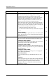
Important Alert Items Task vi Alert message Page Device damage: Be sure to turn on the power supply before inserting your cartridge for the first time. It releases the device from transport protection and enables you to insert the cartridge. The device may be damaged if you insert the cartridge without releasing the protection. From the next time, you don't need to turn on the power supply beforehand. Before moving the drive, remove the optical disk cartridge.
MANUAL ORGANIZATION OPTICAL DISK DRIVE 1. GENERAL DESCRIPTION PRODUCT MANUAL 2. SPECIFICATIONS (C156-E224) 3. INSTALLATION REQUIREMENTS 4. HOST INTERFACE 5. OPERATION AND CLEANING 6. DIAGNOSTICS AND MAINTENANCE OPTICAL DISK DRIVES 1. MAINTENANCE AND DIAGNOSIS MAINTENANCE MANUAL 2. FAULT ANALYSIS (C156-F043) 3. REMOVAL AND REPLACEMENT PROCEDURES 4. PRINCIPLES OF OPERATION 5.
REFERENCED STANDARDS The product specifications and functions described in this manual conform to the following standards: Specification (document) number Name Concerned organization ANSI X3. 131-1986 American National Standard for Information Systems-Small Computer System Interface. (SCSI) ANSI X3. 131-1994 American National Standard for Information Systems-Small Computer System Interface-2.
Contents Preface .........................................................................................................i DISCLAIMER .......................................................................................................iv MANUAL ORGANIZATION ...................................................................................vii CHAPTER 1 General Description.................................................................. 1-1 1.1 Features ............................................
Contents 2.3 Defect Management....................................................................................2-11 2.3.1 CHAPTER 3 Defect management schematic diagram ..............................................2-11 Installation Requirements.........................................................3-1 3.1 Environmental Requirements .......................................................................3-1 3.1.1 3.1.2 3.1.3 3.1.4 3.1.5 3.2 Temperature measurement point ...........................
CHAPTER 4 Host Interface ............................................................................ 4-1 4.1 Interface Connector ......................................................................................4-1 4.2 Various Processes.........................................................................................4-4 4.2.1 Reset response .......................................................................................4-4 4.2.2 Defective sector management ............................
Contents 4.3.21 4.3.22 4.3.23 4.3.24 4.3.25 4.3.26 4.3.27 4.4 SCSI Messages ...........................................................................................4-42 4.4.1 4.4.2 4.4.3 4.5 CHAPTER 5 Message formats ..................................................................................4-42 Message types......................................................................................4-42 Message functions ...............................................................................
6.2 Maintenance Information .............................................................................6-3 6.2.1 6.2.2 Glossary Maintenance requirements ....................................................................6-3 Revision number ...................................................................................6-4 ……………………………………………………………………….GL-1 Abbreviations …….…………………………………………………………………AB-1 Index C156-E224-01EN ………………………………………………………………………...
Contents Illustrations Figures Figure 1.1 Figure 1.2 Figure 1.3 Figure 1.4 Outer view (with panel) .....................................................................................1-7 Outer view (without panel) ................................................................................1-7 Optical disk drive configuration ........................................................................1-8 Control circuit section block diagram..............................................................
Figure 6.1 Revision label ....................................................................................................6-4 Figure 6.2 Revision number indication...............................................................................
Contents Tables Table 2.1 Table 2.2 Table 2.2 Table 2.3 Table 2.3 Table 2.4 xvi Table 2.5 Table 2.6 Model and order number....................................................................................2-1 Specifications (1 of 2)........................................................................................2-2 Specifications (2 of 2)........................................................................................2-3 Environmental and power requirements (1 of 2) ......................
Table 4.31 Table 4.32 Table 4.33 Table 4.34 Table 4.35 Table 4.36 Table 4.37 Table 4.38 Table 4.39 Table 4.40 Table 4.41 Table 4.42 Table 4.43 Table 4.44 Table 4.45 Table 4.46 Table 4.47 Table 4.48 Table 4.49 Table 4.50 Table 4.51 Table 4.52 Table 4.53 Table 4.54 Table 4.55 Table 4.56 Table 4.57 Table 4.58 Table 4.59 Table 4.60 Table 4.61 Table 4.62 Table 4.63 Table 4.64 Table 4.65 Table 4.66 Table 4.67 Table 4.68 Table 4.69 Table 4.70 Table 4.71 Table 4.72 Table 4.73 Table 4.74 Table 4.75 Table 4.
This page is intentionally left blank.
CHAPTER 1 General Description 1.1 Features 1.2 Drive Configuration This chapter describes the features and configuration of the optical disk drives. The MCJ3230SS (hereafter, the optical disk drive) is the successor model to the MCE3130SS. This optical disk drive, which maintains compatibility with the MCE3130SS, offers high performance and high capacity. Supporting 2.3 GB of storage capacity, this device delivers superior performance with a 5,455-rpm rotational speed, and supports security functions.
General Description 1.1 Features This section describes the following drive features: • Performance • Reliability • Maintainability/operability • Adaptability • Interface 1.1.1 Performance (1) Half-height standard 90 mm (3.5-inch) size (25.4 mm height) The SCSI controller can be connected to the system SCSI bus. The controller meets the specifications of the standard 25.4 mm height 90 mm (3.5-inch) fixed disk drive form factor. (2) 2.3 GB capacity The optical disk drive conforms to the 2.
1.1 Features (4) High-speed mean seek time This drive features a linear voice-coil motor for high-speed head positioning. The average seek time is the average of 1,000 random seeks and is 19 ms. (However, this does not include command overhead or address check.) (5) Compatible with international standards (media interchangeability) 90 mm (3.5 inch) type optical disks as well as ISO standards compatible 128 MB, 230 MB, 540 MB and 640 MB format optical disk media can be used in the optical disk unit.
General Description (3) Automatic allocation of alternate data blocks This drive features a function which automatically allocates alternate data blocks to defective data blocks detected while data is being read from or written to an optical disk. 1.1.3 Maintainability/operability (1) Diagnostic function This drive has a diagnostic function to check optical disk drive operations. The diagnostic function facilitates test and restoration.
1.1 Features 1.1.5 Interface (1) Conformance to SCSI-2 This optical disk device supports the basic functions of SCSI-2. SCSI commands enable data manipulation using logical block addresses that are independent of the physical attributes of the optical disk device, enabling software flexibility in terms of system expansion in the future. (2) Continuous block processing Logical block addresses are used for data block addressing.
General Description When the write cache feature is enabled, a write error is reported at the completion status of next command. At a system so that the host retries the command, a retry process may be failed. (6) Defective block slipping When a disk is initialized, logical data blocks are reallocated in a physical sequence by slipping defective data blocks. This enables high-speed continuous data block processing without rotational delay due to defective data blocks.
1.2 Drive Configuration 1.2 Drive Configuration 1.2.1 Drive model Figures 1.1 and 1.2 show the outer view. Figure 1.1 Outer view (with panel) Figure 1.
General Description 1.2.2 Configuration Figure 1.3 shows the drive configuration. The drive consists of mechanical sections, a fixed optics section, actuator, and a control circuit section. The mechanical sections include the spindle motor, actuator section, bias magnet, and the cartridge folder vertical motion mechanism. The fixed optics section consists of the optical components, position detector, and LD controller.
1.2 Drive Configuration 1.2.3 Mechanical sections (1) Optical disk cartridge load/eject The system includes a cartridge mechanism which lowers the optical disk cartridge and mounts (loads) it on the spindle motor automatically when the optical disk cartridge is fully inserted in the optical disk drive's disk slot, and a mechanism which automatically ejects the cartridge when the Eject button on the front panel is pressed.
General Description 1.2.4 Control circuit section Figure 1.4 is the block diagram of the control circuit section. Figure 1.4 Control circuit section block diagram The control circuit section is divided into two parts: a controller section which deals with control between the SCSI interface and drive interface, and a drive circuit section which controls the drive. (1) Controller circuit section The controller circuit's reliability is improved by large-scale integrated circuit technology.
1.2 Drive Configuration The DSP (digital signal processor) is used for the servo/seek control circuit to reduce the circuit amount, therefore this circuit is a simple configuration. The drive circuit section executes operations such as seek, erase, record, and playback while the MPU controls the focus-tracking of the beam.
This page is intentionally left blank.
CHAPTER 2 Specifications 2.1 Optical Disk Drive Specifications 2.2 Optical Disk Cartridge Specifications 2.3 Defect Management This chapter contains the specifications of the optical disk drive, and the optical disk cartridge. 2.1 Optical Disk Drive Specifications 2.1.1 Model and product number Table 2.1 lists the model and order number. Table 2.1 Model and order number Model Name MCJ3230SS Order No. Panel Panel Color Mounting Screws CA05890-B001 with panel Light gray (2.5Y 7.2/0.
Specifications 2.1.2 Drive specifications Table 2.2 lists MCJ3230SS drive specifications Table 2.2 Specifications (1 of 2) Item Optical disk cartridge Total capacity Specifications 128 MB media 230 MB media 540 MB media 640 MB media 1.3 GB media 2.3 GB media Unformatted 181 MB 325 MB 819 MB 818 MB 1.683 GB 2.901 GB Formatted 128 MB 230 MB 538 MB 643 MB 1.283 GB 2.
2.1 Optical Disk Drive Specifications Table 2.2 Specifications (2 of 2) Item Specifications Optical disk cartridge Density 128 MB media 230 MB media 24,424 bpi (1.04µm/bit) 15,875 tpi 29,308 bpi (0.87µm/bit) 18,275 tpi 540 MB media 640 MB media 52,900 bpi (0.48µm/bit) 23,090 tpi 8 sec. (typ) Loading time *3 1.3 GB media 2.3 GB media 89,100 bpi (0.285µm/bit) 28,200 tpi 112,474 bpi (0.228µm/bit) 37,910 tpi 12 sec. (typ) 14 sec. (typ) 4 sec.
Specifications 2.1.3 Environmental and power requirements Table 2.3 lists the environmental and power requirements. Table 2.3 Environmental and power requirements (1 of 2) Item Specification Power requirements Average Power consumption (Average) Ready (active mode) 4.8 W (typical) *2 Random seek, read/ write 6.5 W (typical) *2 Physical Format 7.3 W (typical) *2 Power save mode Pre-idle mode Idle mode Standby mode 4.0 W (typical) *2 2.0 W (typical) *2 1.
2.1 Optical Disk Drive Specifications Table 2.3 Environmental and power requirements (2 of 2) Item Altitude Ambient for purity Specification Operating 3,000 m (10,000 ft) or less Non Operating 12,000 m (40,000 ft) or less Air flow Unused *4 Air purity General office environment or better (dust perticles: Class 5 millions or less) Note: *1 At random seek or read/write. Excluding pulse waveform under 500 us or less.
Specifications 2.1.4 Error rate Data blocks to be accessed are evenly distributed on the disk. Errors due to disk defects are not included. (1) Bit error rate after ECC processing -12 The error rate after ECC processing must be 10 or less. An optical disk cartridge -4 whose raw error rate is 10 or less should be used. (2) Positioning error rate -6 The positioning error rate must be 10 or less. (with retry) 2.1.5 Reliability (1) Mean time between failures (MTBF) The MTBF is 120,000 hours or more.
2.2 Optical Disk Cartridge Specifications 2.2 Optical Disk Cartridge Specifications 2.2.1 Recommended optical disk cartridge specifications The following three disk types comply with the specifications. Table 2.5 shows the specifications of the optical disk cartridge recommended for this optical disk drive. The use of another disk cartridge may lower drive performance. Table 2.
Specifications 2.2.2 Optical disk cartridge Figure 2.1 shows an optical disk cartridge. The figure below shows the cartridge with its shutter open. a. Shutter closed 2) Shutter 1) Cartridge case 3) Write protect tab b. Shutter open 4) Disk 5) Hub Figure 2.
2.2 Optical Disk Cartridge Specifications The following explains the components of the optical disk drive shown in Figure 2.1: 1) Cartridge case Covers the disk to protect it from damage when handled and facilitates disk replacement. The cartridge case is labeled and has a write protect tab. 2) Shutter Protects the disk against dust. When the cartridge is inserted into the optical disk drive, the shutter (metallic door) is opened.
Specifications Table 2.
2.3 Defect Management 2.3 Defect Management 2.3.1 Defect management schematic diagram Defective sectors on the disk shall be replaced by good sectors according to the defect management scheme as follows: Defective sectors found during surface certification are handled by a sector slipping algorithm. Defective sectors found after initialization are handled by a linear replacement algorithm. Figure 2.2 shows the algorithms for alternate processing.
Specifications Figure 2.
CHAPTER 3 Installation Requirements 3.1 Environmental Requirements 3.2 Mounting Requirements 3.3 Power supply Requirements 3.4 Cable Connections 3.5 Settings 3.6 Notes on Drive Handling 3.7 Mounting 3.8 Cable Connections 3.9 Operation Confirmation and Preparation for Use after Installation 3.10 Dismounting Drive This chapter describes environmental, mounting, power supply, and connection requirements. 3.
Installation Requirements a) Inside optical disk cartridge Operating of inner partition wall Tip of thermocouple Hole for inserting thermocouple b) IC (controller, read amp) IC (controller) IC (read amp) IC (power amp) Figure 3.
3.1 Environmental Requirements 3.1.2 Temperature requirements and measuring method Table 3.1 shows the temperature requirement at each measurement point shown in Figure 3.1. Table 3.1 Temperature requirements at measurement points Measurement point Maximum surface temperature Cartridge inside 55°C * IC (controller) surface 90 °C IC (read amp.) surface 95 °C IC (power amp.) surface 90 °C * Following procedure is for temperature measurement of inside cartridge.
Installation Requirements 3.1.4 Temperature rise under several conditions Table 3.2 Temperature at each measuring point (Reference) [Ambient atmospheric temperature of the optical disk drive: 45°C] Measurement point (°C) Ready Random seek Criteria Inside cartridge 47°C 54°C 55°C IC (controller) surface 51°C 68°C 90°C IC (read amp.) surface 48°C 90°C 95°C IC (power amp.) surface 47°C 78°C 90°C Thermal sensor 47°C 55°C − Notes: 1.
3.2 Mounting Requirements 3.2 Mounting Requirements 3.2.1 External dimensions Figures 3.2 to 3.3 show the dimensions of the drive and the positions of the mounting holes. Unit: mm Figure 3.
Installation Requirements Unit: mm Figure 3.
3.2 Mounting Requirements 3.2.2 Installation direction Figure 3.4 shows the permissible installation directions for this drive. The mounting angle tolerance must be within -5 to 10 from the horizontal. (-) shows that the insertion faces below. • Horizontal • Vertical (Two orientations) Disk insertion slot Eject button / Busy LED Manual eject hole Figure 3.
Installation Requirements 3.2.3 Centers of gravity Figure 3.5 shows the centers of gravity of the drive. Figure 3.
3.2 Mounting Requirements 3.2.4 Notes on mounting (1) Mounting frame structure and clearance a) For vibration resistance and heat dissipation, this optical disk drive uses an embossed structure as shown in Figure 3.6, as well as a frame which has a construction similar to other frames which perform the same function. b) As shown in Figure 3.6, the inward projection of the mounting screw from the outer surface of the drive frame must not exceed 3 mm.
Installation Requirements (2) Panel function processing When installed in a cabinet, do not change the panel formal. The processing is installation status and the disk insertion door can be closed from any locations. (3) Service clearance Figure 3.7 shows locations which must be accessed for installation and maintenance. Be sure to leave sufficient service clearance. P side • Cable connection R side • Mounting screw hole Q side • Mounting screw hole Figure 3.
3.3 Power Supply Requirements (7) System ground The optical disk drive should be grounded to the signal ground (SG) of the power supply of the system. This SG line should be supplied with the system. The Frame Ground is shorted in the optical disk drive by a metal strip attached to the vibration isolation rubber between the frame (FG) and the base (SG).
Installation Requirements 3.4 Cable Connections 3.4.1 Drive connectors Figure 3.9 shows the connector and terminal locations. 1 2 3 4 + 12VDC or not connected +12VDC RETURN (GND) or not connected + 5VDC RETURN (GND) + 5VDC Figure 3.9 Connector and terminal locations Power connector (Component side) SCSI connector Front Figure 3.
3.4 Cable Connections PC board Figure 3.
Installation Requirements Table 3.3 Pin assignments Pin No.
3.4 Cable Connections 3.4.2 Cable connector specifications Table 3.4 Recommended components for connection Category SCSI cable Power supply cable Setting terminal Name Model Manufacturer Cable socket (closed-end type) FCN-707B050-AU/B Fujitsu Ltd. Cable socket (through-end type) FCN-707B050-AU/O Fujitsu Ltd. Signal cable UL20184LT25PX28AWG Hitachi Cable, Ltd.
Installation Requirements 3.4.3 Connection Modes Figure 4.3 shows examples of connections between the host system and the optical disk drive. Up to eight devices including the host adapter, optical disk drive, and other SCSI equipment can be connected to the SCSI bus in arbitrary combinations. Install a terminating resistor on the SCSI devices connected to either end of the SCSI cable. See Section 3.4 for the cable connection requirements and power cable connections. a.
3.4 Cable Connections c. Connecting more than one optical disk drive (multi-host) Figure 3.13 SCSI bus connection modes Note: If more than one SCSI device is connected to the same SCSI bus, Fujitsu recommends using an external terminator.
Installation Requirements 3.5 Settings 3.5.1 Default jumper settings Figure 3.14 shows the types of switches and their settings when the drive was shipped. Figure 3.14 Setting terminal (CNH2) 3.5.2 Setting terminal (1) SCSI ID Table 3.5 shows the SCSI ID settings of the drive. Table 3.
3.5 Settings 1) Each SCSI device connected to the same SCSI bus must have a unique SCSI ID. 2) If contention occurs in the ARBITRATION phase, the priority of the SCSI use authority depends on SCSI IDs as follows: 7>6>5>4>3>2>1>0 (2) SCSI terminating resistor mode Enabling or disabling the SCSI terminating resistor, module on the PCA can be set. When the drive positions at other than the end of the SCSI bus, the SCSI terminating resistor should be disabled. Table 3.
Installation Requirements When the write cache feature is enabled, a write error is reported at the completion status of next command. At a system so that the initiator retries the command, a retry process may be failed. (4) Spindle automatic stop mode The optical disk drive automatically enters standby mode if it receives no commands from the host for about 32 minutes (default value). Table 3.
3.6 Notes on Drive Handling 3.6 Notes on Drive Handling (1) General notes Note the following points to maintain drive performance and reliability: Device damage: 1) Shock or vibration applied to the drive that exceeds the values defined in the standard damage the drive. Use care when unpacking. 2) Do not leave the drive in dirty or contaminated environments.
Installation Requirements (3) Installation • Do not connect or disconnect the connectors or change the terminal settings when the power is on. • Do not move the drive with the power on. • Eject the optical disk cartridge, lock the carriage securing the head, turn off the power, then move the drive. Device damage: Be sure to turn on the power supply before inserting your cartridge for the first time. It releases the device from transport protection and enables you to insert the cartridge.
3.6 Notes on Drive Handling Desiccant Desiccant MCJ3230SS Conductive bag MCJ3230SS Conductive bag Eject pin (use a sealing tape) Support (Front, Rear) Eject pin (x 20) Support (Middle) Box Shipping Label (2) Master carton (12/24 units) Single-unit packing Multiple-unit packing Figure 3.15 Packing style (5) Transportation • Transport the optical disk drive packed in principle, with the UP sign upward.
Installation Requirements 3.7 Mounting 3.7.1 Checks before mounting the drive Before mounting the optical disk drive in the system cabinet, check whether the jumper settings are set correctly. 3.7.2 Mounting procedure How the drive is mounted depends on the system cabinet structure. Determine the mounting procedure in consideration of the requirements of each system. This section contains the general mounting procedure and check items. See Section 3.2 for details on mounting drive.
3.8 Cable Connections 3.8 Cable Connections Use the following cables to connect the drive to the system. See Subsection 3.4 for details on the connector positions and cable requirements. • Power supply cable • SCSI interface cable • DC ground cable (if required) The general procedure for cable connection and notes on connecting cables are given below. Pay attention to the insertion direction of each cable connector. • • Make sure that the system power is off.
Installation Requirements 3.9 Operation Confirmation and Preparation for Use after Installation 3.9.1 Confirming initial operations This section provides the operation check procedures after the power is turned on. (1) Initial operation when the power is turned on • When the power is turned on, the drive starts initial self-diagnosis. The LED on the front panel is on for 1 second during initial self-diagnosis. • If an error is detected during initial self-diagnosis, the LED on the front panel blinks.
3.10 Dismounting Drive 3.9.2 Connection check When initial operation check terminates normally after the power is turned on, check whether the drive is correctly connected by issuing command from the host system. Checking procedure depends on the host system configuration. If processing terminates abnormally: 1) If sense data has been obtained by the REQUEST SENSE command, analyze the sense data. If the error is recoverable, retry the processing.
This page is intentionally left blank.
CHAPTER 4 Host Interface 4.1 Interface Connector 4.2 Various Processes 4.3 SCSI Comands 4.4 SCSI Messages 4.5 Timing Rule This chapter describes host interface specification. 4.1 Interface Connector The nonshielded SCSI connector installed on the ODD is a 50-conductor connector consisting of two rows of 25 male pins with adjacent pins 2.54 mm (0.1 in.) apart. See Figure 4.1.
Host Interface Symbol mm Remarks C1 2.540 - C2 60.960 - C3 2.540 - C4 3.302 - C5 32.385 - C6 68.072 - C7 6.096 - C8 7.620 Maximum value Notes: 1. 2. The tolerance is ± 0.127 mm unless otherwise specified. A connector cover and strain relief are not shown in this figure. Figure 4.
4.1 Interface Connector Table 4.
Host Interface 4.2 Various Processes 4.2.1 Reset response Three types of reset responses are available. • Power-On Reset - • • The ODD performs initialization processes such as initial diagnosis and default setting. It also starts rotation of the media, if any is mounted. SCSI Reset - The ODD is reset when the RESET- signal is asserted. The ODD performs initialization of the interface controller, including such operations as writing the default values to the registers.
4.2 Various Processes 4.2.4 Cache function The ODD supports read cache and MO write cache. The read cache consists of the read-ahead cache and the LRU cache that reads write data remaining in the data buffer. The read-ahead cache enables data transfer at almost the same speed as the effective transfer speed during continuous read operation without causing delays resulting from rotation latency.
Host Interface • Data read before power-off • Data stored before media is mounted All buffer data is discarded when: • The power is turned off. • The media is ejected. • A FORMAT UNIT command is received. • The ODD is in standby mode. Buffer data may be discarded when: • A MODE SELECT command that changes the read conditions is received. 4.2.4.
4.2 Various Processes 4.2.6.1 Active mode In active mode, all circuits are enabled and the time for command processing is minimized. 4.2.6.2 Pre-idle mode In pre-idle mode, the read and write circuits are in stopped state. The ODD can receive a command from the host, but since some circuits are stopped, the command requires an additional 20 ms to access the media. The ODD automatically enters pre-idle mode if no command is issued within a specified time (0.5 s) in active mode.
Host Interface 4.2.6.6 Power mode transition The power mode transition is shown in Figure 4.3. Media insertion Active Reset Idle Standby Media ejection (1) The ODD enters idle mode because it receives no command within a specified time. (2) The ODD enters standby mode based on the standby timer. (3) The ODD enters active mode because it receives a media access command. Figure 4.
4.2 Various Processes 4.2.7 LED indications The ODD notifies the operator of a serious error by turning on or blinking an LED. Table 4.2 lists the LED indications and the corresponding operations. Table 4.
Host Interface 4.3 SCSI Commands Table 4.3 lists the SCSI commands supported by MCJ3230SS. Table 4.3 SCSI commands No.
4.3 SCSI Commands 4.3.1 TEST UNIT READY command The TEST UNIT READY command checks whether a logical unit is ready to operate. Table 4.4 TEST UNIT READY command Bit Byte 0 1 2-5 7 6 5 4 3 2 1 0 Operation Code (00h) LUN Reserved Reserved If the ODD power is on and the ODD is ready to operate, the command reports GOOD status. If the ODD is not ready or an error condition remains in the device even though the ODD is ready, the command reports CHECK CONDITION status.
Host Interface Table 4.
4.3 SCSI Commands 4.3.3 READ CAPACITY command Table 4.7 READ CAPACITY command Bit Byte 0 1 2-7 8 9 7 6 5 4 3 2 1 0 Operation Code (25h) LUN Reserved Reserved Reserved Reserved PMI The READ CAPACITY command transfers data related to the media capacity to INIT. Any value specified for the Partial Medium Indicator (PMI) bit is ignored. The transfer data is listed in Table 4.8. Table 4.
Host Interface parameters are incomplete, the command responds with Check Condition without any processing. Table 4.10 lists the pages supported. Table 4.10 Mode page codes Definition Read-Write Error Recovery Page Flexible Disk Page Caching Page Power Condition Page Verify Control Page Page Code 01h 05h 08h 1Ah 3Eh Table 4.11 is a mode parameter list. Table 4.
4.3 SCSI Commands Table 4.13 Block descriptor Bit Byte 0 1-3 4 5-7 7 6 5 4 3 2 1 0 2 1 0 1 0 Reserved DCR Density Code (00h) Number of Blocks Reserved Block Length Table 4.14 shows the format of the Mode Page field. Table 4.14 Mode page Bit Byte 0 1 2-n 7 6 PS 0 5 4 3 Page Code Page Length (n-1) Mode Parameters (1) Read/write error recovery page Table 4.
Host Interface • Seven or eight error bytes occurring per interleaving are corrected by the ECC feature during a read operation. • A defective sector is detected and replaced with an alternate sector during a write operation. • An error occurs in one of four sets of media data during media management information (DMA) write operation caused by the FORMAT UNIT command (MEDIUM ERROR is set if an error occurs in two, three, or four sets of four sets).
4.3 SCSI Commands (2) Flexible disk page Table 4.18 Flexible disk page Bit Byte 0 1 2-3 4 5 6-7 8-9 10-19 20 21-27 28-29 30-31 7 6 0 0 5 4 3 2 1 0 Page Code (05h) Page Length (1Eh) Transfer Rate Number of Heads Sectors per Track Data Bytes per Sector Number of Cylinders Reserved Motor off Delay Reserved Medium Rotation Rate Reserved The Flexible disk page is only supported for compatibility of device drivers.
Host Interface Table 4.19 Variable values in the flexible disk page Bit Byte 2-3 4 5 6-7 8-9 10-19 20 21-27 28-29 30-31 7 6 5 4 3 2 1 0 1 0 0000h 00h 00h 00h 0000h 0000h 00h 00h 0000h 00h Table 4.20 Default values in the flexible disk page Bit Byte 2-3 4 5 6-7 8-9 10-19 20 21-27 28-29 30-31 4-18 7 6 5 4 3 2 3E80h 40h 20h 640 MB, 1.3 GB, or 2.
4.3 SCSI Commands (3) Caching page Table 4.21 Caching page Bit Byte 0 1 2 3-19 7 6 PS (1) 0 5 4 3 2 Page Code (08h) Page Length (12h) Reserved WCE Reserved 1 0 Reserved RCD If the Write Cache Enable (WCE) bit is 0, the write cache function for the WRITE (6), WRITE (10), and WRITE AND VERIFY commands is disabled. If the bit is 1, the write cache function is enabled. If the Read Cache Disable (RCD) bit is 0, the read-ahead cache function for the READ (6) and READ (10) commands is enabled.
Host Interface Any values specified for the Idle bit or Idle Condition Timer bits are ignored. The ODD always uses the default timer values. If the Standby bit is 1, Standby Condition Timer defines the time elapsed before the ODD enters standby mode after it enters idle mode. Specify the values for Idle Condition Timer and Standby Condition Timer in units of 100 ms.
4.3 SCSI Commands If the Streaming Mode (SM) bit is 0, a test write operation may interrupt a read or write operation. If the bit is 1, the test write operation is suppressed during continuous read or write operation. Fujitsu recommends setting the SM bit to 0. Verify Mode (VM) specifies a verify operation for the WRITE command. Table 4.28 Verify mode VM 0 1 2 3 Description Always enable verify operation. Always disable verify operation. Conditionally enable verify operation (verify skip mode).
Host Interface 4.3.5 MODE SENSE command Table 4.31 MODE SENSE command Bit Byte 0 1 2 3 4 5 7 6 5 Reserved PC 4 3 2 Operation Code (1Ah) DBD Page Code Reserved Allocation Length Reserved 1 0 Reserved The MODE SENSE command transfers a mode parameter list to INIT. If Disable Block Descriptor (DBD) is 1, the command does not return a block descriptor. If DBD is 0, the command returns a block descriptor. Allocation Length specifies the number of bytes of the mode parameter to be transferred.
4.3 SCSI Commands Table 4.33 Mode parameters Bit Byt e 0-4 0-7 0-n 7 6 5 4 3 2 1 0 Mode Parameter Header Block Descriptor Mode Page (s) The mode parameter list consists of Mode Parameter Header, Block Descriptor, and Mode Page. Table 4.34 shows the format of the Mode Parameter Header field. Table 4.
Host Interface Each field value of Block Descriptor is valid only when accessible media is inserted. If accessible media is not inserted, 0 is returned. Table 4.36 shows the format of the Mode Page field. Table 4.36 Mode Page Bit Byte 0 1 2-n 7 6 PS 0 5 4 3 2 1 0 1 0 Page Code Page Length (n-1) Mode Parameters If PS is 1, page data can be saved to flash ROM. 4.3.6 START/STOP UNIT command Table 4.
4.3 SCSI Commands 4.3.7 RESERVE command Table 4.39 RESERVE command Bit Byte 0 1 2-5 7 6 5 4 3 2 1 0 Operation Code (16h) LUN Reserved Reserved As with the RELEASE command (explained next), the RESERVE command controls exclusive access to the logical unit (ODD) in a multi-initiator environment. The ODD is reserved for another SCSI device by the INIT that issues this command. Any values specified for CDB bytes 1 to 5 are ignored. However, INIT should specify 00h for these bytes.
Host Interface 4.3.8 RELEASE command Table 4.40 RELEASE command Bit Byte 0 1 2-5 7 6 5 4 3 2 1 0 Operation Code (17h) LUN Reserved Reserved The RELEASE command releases the ODD reserved by the INIT that issued this command. When any of the following conditions is met, the command ends with GOOD status but it does not affect the reserved status of the ODD: • The reserved status created by the INIT that has issued this command is not in the ODD.
4.3 SCSI Commands Table 4.42 shows the format of the Sense Data field. Table 4.42 Request Sense Data Bit Byte 0 1 2 3-6 7 8-11 12 13 14 15-17 18-31 7 Valid 6 5 4 3 2 1 0 Error Code (70h or 71h) Reserved (00h) Reserved (0h) Sense Key Information Additional Sense Length (18h) Command-Specific Information Additional Sense Code Additional Sense Code Qualifier Reserved (00h) Sense-key specific Additional Sense Bytes If the Valid bit is 1, the Information field is valid.
Host Interface Table 4.44 Sense Key Sense Mnemonic Key 0h NO SENSE 1h RECOVERED ERROR 2h 3h NOT READY MEDIUM ERROR HARDWARE ERROR ILLEGAL REQUEST UNIT ATTENTION DATA PROTECT BLANK CHECK Reserved 4h 5h 6h 7h 8h 9hAh Bh ChFh ABORTED COMMAND Reserved Meaning There is no sense key to be reported. NO SENSE is set when a command ends normally. Recovery processing ended successfully or the commands ended normally using the internal default values even though invalid data was detected in command parameters.
4.3 SCSI Commands Table 4.
Host Interface Sense Key B 4 5 4 ASC ASCQ 4E 53 53 83 00 00 02 00 Error description OVERLAPPED COMMAND ATTEMPTED MEDIA LOAD OR EJECT FAILED MEDIUM REMOVAL PREVENTED THERMAL ERROR Table 4.47 shows the format of the Sense-Key Specific field. Progress Indication is valid only when Sense Key is NOT READY and the SKSV bit is 1. Otherwise, the field is set to 00h. This field is defined for the FORMAT UNIT command with the Immed bit set to 1. Table 4.
4.3 SCSI Commands 4.3.10 PREVENT/ALLOW MEDIUM REMOVAL command Table 4.48 PREVENT/ALLOW MEDIUM REMOVAL command Bit Byte 0 1 2-3 4 5 7 6 5 4 3 2 1 0 Operation Code (1Eh) LUN Reserved Reserved Reserved Reserved Prevent The PREVENT/ALLOW MEDIUM REMOVAL command enables or disables media ejection from the device. If the Prevent bit is 0, ejection is enabled. If the Prevent bit is 1, ejection is disabled. At power-on, media ejection is enabled by default.
Host Interface 4.3.11 READ (6) command The READ (6) command reads the specified number of blocks of data from the specified logical block address and transfers it to INIT. Table 4.50 CDB of READ (6) command Bit Byte 0 1 2 3 4 5 7 6 5 4 3 2 1 0 Operation Code (08h) (MSB) Logical Block Address LUN (LSB) Transfer Length Reserved Logical Block Address specifies the logical block address at which the command should start reading data.
4.3 SCSI Commands 4.3.13 VERIFY command Table 4.52 VERIFY command Bit Byte 0 1 2-5 6 7-8 9 7 6 5 4 3 2 Operation Code (2Fh) Reserved Logical Block Address Reserved Verification Length Reserved LUN 1 0 ByteChk Reserved The VERIFY command verifies the specified number of blocks beginning at the specified logical block address. Logical Block Address specifies the logical block address at which the command should start verifying data.
Host Interface • The Verify mode setting in the mode parameter (Verify Control Page) can be set to omit verify processing. Omitting verify processing shortens processing time by about 25%. 4.3.15 WRITE (10) command Table 4.
4.3 SCSI Commands 4.3.17 SEEK (6) command Table 4.56 SEEK (6) command Bit Byte 0 1 2 3 4-5 7 6 5 4 3 2 1 0 Operation Code (0Bh) (MSB) Logical Block Address LUN (LSB) Reserved The SEEK (6) command performs a seek operation on the block specified by the logical block address. • After finishing the seek operation normally, the command reports GOOD or INTERMEDIATE GOOD status. If the command fails in the seek operation, it reports CHECK CONDITION status.
Host Interface 4.3.19 ERASE command Table 4.58 ERASE command Bit Byte 0 1 2-5 6 7-8 9 7 6 5 4 3 2 1 0 Operation Code (2Ch) LUN Reserved Logical Block Address Reserved Transfer Length Reserved The ERASE command erases the specified number of blocks of data beginning at the specified logical block address. Logical Block Address specifies the logical block address at which the command should start writing data. Transfer Length specifies the number of blocks of data to be transferred and written.
4.3 SCSI Commands 4.3.21 FORMAT UNIT command Table 4.60 FORMAT UNIT command Bit Byte 0 1 2 3-4 5 7 6 5 4 3 2 1 0 Operation Code (04h) FmtData LUN CmpList Defect List Format 0 0 Reserved Interleave Reserved The FORMAT UNIT command physically formats media according to the specified parameter values. If the FmtData bit is 1, a FORMAT UNIT parameter list must be transferred. The command ignores Defect List Format.
Host Interface 4.3.22 READ DEFECT DATA command Table 4.63 READ DEFECT DATA command Bit Byte 0 1 2 3-6 7-8 9 7 6 5 4 3 2 1 0 Operation Code (37h) LUN Reserved Plist Glist Reserved Allocation Length Reserved Reserved Defect List Format The READ DEFECT DATA command transfers media defect data to INIT. If Plist is 1, the command transfers the header and PDL. If Glist is 1, the command transfers the header and SDL. If Plist and Glist are both 0, the command transfers the header.
4.3 SCSI Commands Table 4.66 Defect descriptor Byte 0-2 3 4-7 Defect Descriptor Track address of defective block 00h Sector address of defective block (See Table 4.67.) Table 4.67 Sector address format Bit Byte 0-2 3 7 6 0 5 4 00h 00b 00b groove 10b land Media other than 2.3 GB: 2.3-GB media: 3 2 1 0 Sector address 4.3.23 SEND DIAGNOSTIC command Table 4.
Host Interface The RECEIVE DIAGNOSTIC RESULTS command transfers the results of the diagnosis specified by the SEND DIAGNOSTIC command to INIT. The RECEIVE DIAGNOSTIC RESULTS command is issued following the SEND DIAGNOSTIC command. If the command does not follow the SEND DIAGNOSTIC command or if there is no data to be transferred, the command ends normally without transferring any data. 4.3.25 WRITE BUFFER command Table 4.
4.3 SCSI Commands 4.3.26 READ LONG command Table 4.71 READ LONG command Bit Byte 0 1 2-5 6 7-8 9 7 6 5 4 3 2 1 0 Operation Code (3Eh) LUN Reserved Logical Block Address Reserved Byte Transfer Length Reserved The READ LONG command reads data in the data, CRC, and ECC sections from the specified logical block address. The length of the transfer data must be a multiple of 600 (258h) bytes for 512-byte media and a multiple of 2380 (94Ch) bytes for 2048-byte media. 4.3.27 WRITE LONG command Table 4.
Host Interface 4.4 SCSI Messages SCSI messages are used to control the SCSI bus operating sequence. This section explains how SCSI messages work. 4.4.1 Message formats There are three types of message formats. In any format, the first byte of each message is a message code (see Table 4.73). • 1-byte message: Only the message code • 2-byte message: Message with a message code from 20h to 2Fh. Each 2byte message consists of a 1-byte message code and a 1byte parameter.
4.4 SCSI Messages 4.4.3 Message functions This section explains the function of each message. The symbols in the following explanations have the following meanings: (I → T): Message that can only be sent from INIT to TARG (T → I): Message that can only be sent from TARG to INIT (I ←→ T): Message that can be sent between TARG and INIT in either direction (1) COMMAND COMPLETE message: 00h (T → I) The execution of a single command ended and valid status information was reported to INIT.
Host Interface (6) MESSAGE REJECT message: 07h (I → T) The message received most recently is invalid or unsupported. (7) NO OPERATION message: 08h (I → T) This message causes no operation. (8) MESSAGE PARITY ERROR message: 09h (I → T) This message notifies TARG that a parity error was detected in the last message, in the last byte received by the INIT. (9) BUS DEVICE RESET message: 0Ch (I → T) This message instructs the clearing of all I/O operations (commands) being executed or stacked in TARG.
4.4 SCSI Messages Table 4.74 lists the values of Transfer Period and the corresponding synchronous transfer rates. Table 4.
Host Interface 4.5 Timing Rule Table 4.75 Timing specifications (1 of 3) No. Name Standard Timing specification 1 Arbitration Delay 2.4 µs min. The minimum wait period between the time the SCSI device sends a BSY signal and the time the value on the data bus for determining the priority of bus use is judged in the ARBITRATION phase. A maximum time is not defined. 2 Assertion Period 90 ns min.
4.5 Timing Rule Table 4.75 Timing specifications (2 of 3) No. Name 6 Bus Settle Delay 400 ns min. Minimum wait period between the time a particular control signal condition changes and the time the bus condition is stabilized. 7 Cable Skew Delay 10 ns max. Maximum allowable difference in transmission time over the interface cable between any two bus signals from any two SCSI devices. 8 Data release Delay 400 ns max.
Host Interface Table 4.75 Timing specifications (3 of 3) No. 4-48 Name Standard Timing specification 16 Selection Timeout Delay 250 ms min. [Recommende d value] In a SELECTION or RESELECTION phase, the minimum time during which the INIT or TARG waits for a BSY signal from the SCSI device to be selected before it initiates timeout processing.
4.5 Timing Rule Table 4.76 FAST SCSI Timing specifications No. Name Standard 30 ns min. Timing specification 18 Fast Assertion Period In FAST SCSI data transfer mode, minimum pulse width of an ACK signal sent by INIT and an REQ signal sent by TARG for synchronous data transfer. 19 Fast Cable Skew 5 ns max. Delay In FAST SCSI data transfer mode, maximum allowable difference in transmission time over the interface cable between any two bus signals from any two SCSI devices.
Host Interface Figure 4.
4.5 Timing Rule µ Figure 4.6 SELECTION phase Figure 4.
Host Interface Figure 4.
4.5 Timing Rule Figure 4.
Host Interface Figure 4.
CHAPTER 5 Operation and Cleaning 5.1 Operating Optical Disk Drive 5.2 Cleaning Drive 5.3 Optical Disk Cartridge Operation 5.4 Cleaning Optical Disk Cartridge This chapter describes how to operate and clean the drive and the optical disk cartridges. 5.1 Operating Optical Disk Drive The drive has an automatic load function. All the operator must do is to insert the optical disk cartridge and operate the eject button.
Operation and Cleaning 5.1.1 Optical disk drive •• Horizontal Horizontal Disk insertion slot Eject button / Busy LED Manual eject hole • Vertical (Two orientations) Figure 5.1 Optical disk drive front view (with panel) The following explains the parts and functions of the optical disk drive (the following numbers correspond to the numbers in Figures 5.1): 1) Disk insertion slot Use this slot to insert and eject the optical disk cartridge.
5.1 Operating Optical Disk Drive 5.1.2 Note To maintain the performance and reliability of the drive, keep the following point in mind: • When the drive is in the busy state, do not eject the optical disk cartridge. Particularly, do not manually eject the cartridge by force. • Be careful sufficiently not to insert the different drive (etc. floppy disk) or substance, so it is cause of the accident. 5.1.3 Inserting cartridge Insert the cartridge as explained below. (See figure 5.
Operation and Cleaning 4) Push the cartridge into the slot until it completes moving below (a little further in than the operator panel). The cartridge remains inserted in the drive. The BUSY LED indicator lamp lights when the drive power is turned on. The cartridge remains inserted in the drive. Turning on the drive power starts loading. (The LED indicator lamp should light.
5.1 Operating Optical Disk Drive 5.1.4 Ejecting (removing) cartridge Remove the cartridge as explained below. (1) When the drive power is on: The cartridge can be removed by pressing the eject button. (See figure 5.3) Notes: 1) If the SCSI command prevents ejection, the cartridge cannot be removed. 2) Even if the drive set-up conditions are met, note that the cartridge can drop from the drive after ejection depending on the ambient environment and the cartridge's condition.
Operation and Cleaning 5.2 Cleaning Drive When a dust or smoke of cigarette is stained to the lens actuator, a performance of whole drive may be down. Clean the lens actuator periodically using following head cleaner. Note: Cleaning period differs depending on the installation condition. Usually, cleaning period is once a three months. Table 5.1 Head cleaner Part name Product number Order number Head cleaner 020470 CA90002-C980 (1) Cleaning method Clean the head actuator with following method. 1.
5.3 Optical Disk Cartridge Operation 5.3 Optical Disk Cartridge Operation 5.3.1 Optical disk cartridge Figure 5.4 shows the optical disk cartridge. For operation and cleaning, users should be familiar with the parts shown in the figure. See Subsection 2.3.2 for the functions of the parts. a. Shutter closed 2. Shutter 1. Cartridge case 3. Write protect tab b. Shutter open 4. Disk 5. Hub Figure 5.
Operation and Cleaning 5.3.2 Write protect tab Moving the write protect table determines whether to enable or disable writing of the optical disk cartridge. Use a fingernail to move the write protect tab (it must be completely moved to the end because there is play in the middle). Figure 5.5 shows the write protect tab location on the optical disk cartridge and the moving state of the write protect tab (see "write enabled" and write disabled" entered on the label).
5.3 Optical Disk Cartridge Operation 5.3.3 How to affix an index label on the MO cartridge (See figure 5.6) (1) Note the following when affixing an index label: • Be careful not to let the label become misaligned. • Be sure to prevent the formation of air bubbles or peeling. (2) How to affix an index label Follow the procedure below when affixing an index label. (See Figure 5.x.) 1) Clean the surface of the MO cartridge before affixing the index label.
Operation and Cleaning (2) When storing the cartridge: • Do not place a heavy objects on the cartridge. • Do not store the cartridge where exposed to direct sunlight or where the temperature changes sharply, the temperature is high, or the humidity is high. • Do not store the cartridge in a dusty or smoky place. (3) When transporting the cartridge: 5-10 • Put the cartridge in a nylon bag to protect it from moisture.
5.4 Cleaning Optical Disk Cartridge 5.4 Cleaning Optical Disk Cartridge Dust or cigarette smoke particulates on the disk surface lowers the performance of the cartridge. Regularly clean the disk. The cleaning frequency depends on the drive installation environment. Determine how often the drive should be cleaned in consideration of the environment. A standard of he cleaning period is every 300 hours usage or once a 2 to 3 months. 5.4.1 Cleaning tool Use the cleaning kit to clean the disk cartridge.
Operation and Cleaning Damage for disk medium: Use the cleaning solution and cleaning cloth specified in Table 5.2. If other than the specified items is used, disk media surface may be damaged. (2) Notes on usage and storage of cleaning kit • When storaging the cleaning solution, tighten the cap. • As the magnet is used at revolving knob of the setting case, do not place the floppy disk near the revolving knob. • Do not use or storage where exposed to direct sun light or near the inflammables.
5.4 Cleaning Optical Disk Cartridge 2) Set the cartridge with keeping label side down and shutter open to the shutter stopper of the setting case as shown in Figure 5.8. Cartridge Shutter Spindle Disk media Shutter stopped Setting case as shown Setting case Figure 5.8 Cleaning procedure (2) Damage for disk medium: At setting the cartridge to the setting case, do not apply the heavy shock and push hardly.
Operation and Cleaning Eye inflammation: In case of contact with eyes, immediately flush eyes with water. 6) Wipe the disk surface from the hub outward. 7) Turn the revolving knob, then wipe the disk surface. Cleaning cloth Figure 5.10 Cleaning procedure (4) 8) If the excess cleaning solution remains on the disk surface, wipe out with the cleaning cloth.
CHAPTER 6 Diagnosis and Maintenance 6.1 Diagnosis 6.2 Maintenance Information This chapter contains diagnosis and maintenance information. 6.1 Diagnosis Table 6.1 shows a test executed by the diagnostic function. The drive has a self-diagnostic function. This function can check the basic operations of the drive. A test program running in the host system is required to check general operations, including operations of the interface with the host system. (See Subsection 6.1.3.) Table 6.
Diagnosis and Maintenance 6.1.2 Diagnostic command The host system can make the ODD execute the self diagnosis by issuing the EXECUTIVE DEVICE DIAGNOSTIC command. See Section 4.7.2, "EXECUTIVE DEVICE DIAGNOSTIC", in details. 6.1.3 Test program A test program running in the host system is required to check general operations such as operations of the interface with the host system and simulated operations. The configuration and function of the test program depend on the user system requirements.
6.2 Maintenance Information 6.2 Maintenance Information 6.2.1 Maintenance requirements (1) Preventive maintenance No preventive maintenance is required. (2) Service life No overhaul is required within the first five years if the drive is used and handled in an appropriate environment. (3) Service system and repair Fujitsu provides a service system and repair facility for its optical disk drive. Submit information required to replace or repair the drive to your Fujitsu representative.
Diagnosis and Maintenance 6.2.2 Revision number The revision number of an optical disk drive is represented with an alphabetic character and a single-digit number. The revision number is shown on the revision label attached to the drive. For example, Figure 6.1 shows the revision label format. Revision number Figure 6.
Glossary Axial acceleration Acceleration on the recording layer along with the line perpendicular to the disk reference surface to a specified rotation speed. Axial acceleration is detected by optical means. Axial displacement A displacement at a point on the recording layer in a direction perpendicular to the disk reference surface from its original standard position.
Glossary Disk reference surface An ideal flat ring surface of an ideal spindle that is in contact with the clamp area on the disk. It is perpendicular to the rotation axis. Error correction code An error correction code designed to correct specific errors in data. Error detection and correction A series of data by adding a redundant code to data in the existing format. In read mode, the decoder removes a redundant code and detects and corrects errors using redundant information.
Glossary Status A single-byte information reported from the target to the initiator at the end of each command execution. The status indicates the end status of a command.
This page is intentionally left blank.
Acronyms and Abbreviations A AC ACK ALPG AM ANSI ARRE ASC ASCII ASCQ ATN AWG AWRE Alternating Current ACKnowledge Automatic Laser Power Control Address Mark American National Standards Institute Automatic Read Reallocation Enabled Additional Sense Code American Standard Code for Information Interchange Additional Sense Code Qualifier ATteNtion American Wire Gauge Automatic Write Reallocation Enabled E EBC EBP ECC EN EVPD F FG FIFO FmtData FOV FRU Buffer Control Valid Bit Pointer Varid BuSY Byte Check
Acronyms and Abbreviations N N.C.
Fujitsu Internal Use Only Index 128 MB disk 2-9 1.3 GB disk 2-9 230 MB disk 2-9 2.3 GB capacity 1-2 2.
Index Fujitsu Internal Use Only defect management schematic diagram 2-11 device driver software 1-6 diagnosis 6-1 diagnosis and maintenance 6-1 diagnostic command 6-2 diagnostic function 1-4 dimension (without panel) 3-6 direct-overwrite medium support 1-3 DISCONNECT message 4-43 disk 2-9 disk specification 2-9 dismounting drive 3-27 drive circuit section 1-10 drive configuration 1-7 drive connector 3-12 drive model 1-7 drive specification 2-2 dust resistance 1-3 E ejecting (removing) cartridge 5-5 enviro
Fujitsu Internal Use Only MODE SELECT command 4-13 MODE SENSE command 4-22 mounting 3-24 mounting frame structure 3-9 mounting frame structure and clearance 3-9 mounting procedure 3-24 mounting requirement 3-5 MO write cache 4-6 MTBF 1-3, 2-6 N NO OPERATION message 4-44 note 5-3 note following when affixing index label 5-9 notes 5-9 notes on drive handling 3-21 notes on mounting 3-9 notes on usage and storage of cleaning kit 5-12 O operability 1-4 operating optical disk drive 5-1 operation and cleaning 5-1
Index Fujitsu Internal Use Only SCSI terminating resistor mode 3-19 SCSI terminating resistor mode (CNH1) 3-19 sector address format 4-39 SEEK (10) command 4-35 SEEK (6) command 4-35 SELECTION phase 4-51 self-diagnostic function 6-1 SEND DIAGNOSTIC command 4-39 Sense Key 4-28 separator optical section 1-9 service clearance 3-10 service life 2-6, 6-3 service system and repair 6-3 setting 3-18 setting terminal 3-18 setting terminal (CNH2) 3-18 shape of setting terminal 3-13 shutter 2-9 shutter closed 2-8, 5
Comments concerning this manual can be directed to one of the following addresses: FUJITSU LIMITED Storage Product Group 4-1-1, Kamikodanaka, Nakahara-ku, Kawasaki 211-8588, Japan TEL: 81-44-754-8350 FAX: 81-44-754-8351 FUJITSU COMPUTER PRODUCTS OF AMERICA, INC. 2904 Orchard Parkway, San Jose, California 95134-2009, U.S.A. TEL: 1-408-432-6333 FAX: 1-408-894-1709 FUJITSU CANADA INC. 2800 Matheson Blvd.
This page is intentionally left blank.
READER’S COMMENT FORM Your comments or suggestions on this document are cordially solicited. For any comments and suggestions you may have, please complete and submit this form to your FUJITSU representative. The comments and suggestions will be used in planning future editions. Thank you for your cooperation.