C141-E224-01EN MHV2100BH, MHV2080BH MHV2060BH, MHV2040BH DISK DRIVES PRODUCT MANUAL
FOR SAFE OPERATION Handling of This Manual This manual contains important information for using this product. Read thoroughly before using the product. Use this product only after thoroughly reading and understanding especially the section “Important Alert Items” in this manual. Keep this manual handy, and keep it carefully. FUJITSU makes every effort to prevent users and bystanders from being injured or from suffering damage to their property. Use the product according to this manual.
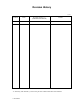
Revision History (1/1) Edition Date 01 2005-04-28 Revised section (*1) (Added/Deleted/Altered) Details *1 Section(s) with asterisk (*) refer to the previous edition when those were deleted.
This page is intentionally left blank.
Preface This manual describes MHV2100BH, MHV2080BH, MHV2060BH, MHV2040BH model of the MHV Series, 2.5-inch hard disk drives. These drives have a built-in controller that is compatible with the Serial-ATA interface. This manual describes the specifications and functions of the drives and explains in detail how to incorporate the drives into user systems. This manual assumes that the reader has a basic knowledge of hard disk drives and their implementations in computer systems.
Preface Conventions for Alert Messages This manual uses the following conventions to show the alert messages. An alert message consists of an alert signal and alert statements. The alert signal consists of an alert symbol and a signal word or just a signal word. The following are the alert signals and their meanings: This indicates a hazardous situation could result in minor or moderate personal injury if the user does not perform the procedure correctly.
Preface Attention Please forward any comments you may have regarding this manual. To make this manual easier for users to understand, opinions from readers are needed. Please write your opinions or requests on the Comment at the back of this manual and forward it to the address described in the sheet. Liability Exception “Disk drive defects” refers to defects that involve adjustment, repair, or replacement.
This page is intentionally left blank.
Important Alert Items Important Alert Messages The important alert messages in this manual are as follows: A hazardous situation could result in minor or moderate personal injury if the user does not perform the procedure correctly. Also, damage to the product or other property, may occur if the user does not perform the procedure correctly. Task Normal Operation Alert message Page Data corruption: Avoid mounting the disk near strong magnetic sources such as loud speakers.
This page is intentionally left blank.
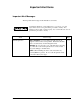
Manual Organization MHV2100BH, MHV2080BH MHV2060BH, MHV2040BH DISK DRIVES PRODUCT MANUAL (C141-E224) • • • • • • Device Overview Device Configuration Installation Conditions Theory of Device Operation Interface Operations MHV2100BH, MHV2080BH MHV2060BH, MHV2040BH • Maintenance and Diagnosis • Removal and Replacement Procedure DISK DRIVES MAINTENANCE MANUAL (C141-F074) C141-E224 vii
This page is intentionally left blank.
Contents CHAPTER 1 Device Overview........................................................................ 1-1 1.1 Features ..............................................................................................................1-2 1.1.1 Functions and performance .....................................................................1-2 1.1.2 Adaptability .............................................................................................1-2 1.1.3 Interface....................................
Contents CHAPTER 2 Device Configuration................................................................ 2-1 2.1 Device Configuration ....................................................................................... 2-2 2.2 System Configuration ....................................................................................... 2-3 2.2.1 SATA interface..................................................................................... 2-3 2.2.2 Drive connection ...............................
Contents 4.6 Read/write Circuit ..............................................................................................4-9 4.6.1 Read/write preamplifier (PreAMP).........................................................4-9 4.6.2 Write circuit.............................................................................................4-9 4.6.3 Read circuit............................................................................................4-10 4.6.4 Digital PLL circuit...........................
Contents 5.2.3.1 FIS types .................................................................................. 5-17 5.2.3.2 Register - Host to Device ........................................................ 5-17 5.2.3.3 Register - Device to Host ........................................................ 5-18 5.2.3.4 DMA Active - Device to Host................................................. 5-18 5.2.3.5 DMA Setup - Device to Host or Host to Device (Bidirectional)...............................................
Contents (24) FLUSH CACHE (X’E7’) ............................................................. 5-86 (25) WRITE BUFFER (X’E8’)............................................................. 5-87 (26) IDENTIFY DEVICE (X’EC’)....................................................... 5-88 (27) IDENTIFY DEVICE DMA (X’EE’)............................................ 5-89 (28) SET FEATURES (X’EF’) ........................................................... 5-101 (29) SECURITY SET PASSWORD (X’F1’) .....................
Contents 5.4.5 DMA data-out command protocol ................................................... 5-152 5.4.6 Native Command Queuing protocol ................................................ 5-153 5.5 Power-on and COMRESET.......................................................................... 5-156 CHAPTER 6 Operations ................................................................................. 6-1 6.1 Reset and Diagnosis.........................................................................
Contents Glossary ........................................................................................................... GL-1 Acronyms and Abbreviations.........................................................................AB-1 Index .................................................................................................................
Contents Illustrations Figures Figure 1.1 Negative voltage at +5 V when power is turned off............................ 1-6 Figure 1.2 Current fluctuation (Typ.) at +5 V when power is turned on.............. 1-8 Figure 2.1 Disk drive outerview............................................................................ 2-2 Figure 2.2 Drive system configuration ................................................................. 2-3 Figure 3.1 Figure 3.2 Figure 3.3 Figure 3.4 Figure 3.5 Figure 3.6 Figure 3.
Contents Figure 5.11 Figure 5.12 Figure 5.13 Figure 5.14 Figure 5.15 Figure 5.16 Figure 5.17 Figure 5.18 Figure 5.19 Non-data command protocol ..........................................................5-147 PIO data-in command protocol ......................................................5-149 PIO data-out command protocol ....................................................5-150 DMA data-in command protocol ...................................................5-151 DMA data-out command protocol ...........
Contents Tables Table 1.1 Table 1.2 Table 1.3 Table 1.4 Table 1.5 Table 1.6 Table 1.7 Table 1.8 Specifications ....................................................................................... 1-4 Examples of model names and product numbers ................................. 1-5 Current and power dissipation .............................................................. 1-7 Environmental specifications................................................................ 1-8 Acoustic noise specification ..
Contents Table 5.26 Features field values and settable modes ........................................5-101 Table 5.27 Contents of SECURITY SET PASSWORD data............................5-106 Table 5.28 Relationship between combination of Identifier and Security level, and operation of the lock function .........................5-106 Table 5.29 Contents of security password .........................................................5-114 Table 5.30 Data format of Read Log Ext log page 10h.......................
This page is intentionally left blank.
CHAPTER 1 Device Overview 1.1 Features 1.2 Device Specifications 1.3 Power Requirements 1.4 Environmental Specifications 1.5 Acoustic Noise 1.6 Shock and Vibration 1.7 Reliability 1.8 Error Rate 1.9 Media Defects 1.10 Load/Unload Function 1.11 Advanced Power Management (APM) 1.12 Interface Power Management (IPM) Overview and features are described in this chapter, and specifications and power requirement are described. The disk drive is 2.
Device Overview 1.1 Features 1.1.1 Functions and performance The following features of the disk drive are described. (1) Compact The disk drive has up to 2 disks of 65 mm (2.5 inches) diameter, and its height is 9.5 mm (0.374 inch). (2) Green product The disk drive is lead (Pb)-free products and the European Parliament and Council Directive on the Restriction of the use of certain Hazardous Substances in electrical and electronic equipment (the RoHS Directive) compliant.
1.1 Features (3) Low noise and vibration In Ready status (while the device is waiting for any commands), the Sound Power level of the disk drives in idle mode is 2.2B [MHV2040BH]/2.6B[MHV2060BH, MHV2080BH, MHV2100BH]. The Sound Pressure level is 22dB [MHV2040BH]/28dB [MHV2060BH, MHV2080BH, MHV2100BH], as measured 0.3 m from the drive in Idle mode. (4) High resistance against shock The Load/Unload mechanism is highly resistant against non-operation shock up 2 to 8820 m/s (900G). 1.1.
Device Overview 1.2 Device Specifications 1.2.1 Specifications summary Table 1.1 shows the specifications of the disk drives. Table 1.1 Specifications (1 of 2) MHV2100BH MHV2080BH MHV2060BH MHV2040BH Format Capacity (*1, *2) 100 GB 80 GB 60 GB 40 GB Number of Sectors (User) 195,371,568 156,301,488 117,210,240 78,140,160 Bytes per Sector 512 bytes Rotational Speed 5,400 rpm ± 1% Average Latency 5.56 ms Positioning time (read and seek) 1.5 ms (typ.
1.2 Device Specifications Table 1.1 lists the formatted capacity, number of logical cylinders, number of heads, and number of sectors of every model for which the CHS mode has been selected using the BIOS setup utility on the host. Table 1.1 Specifications (2 of 2) Model Capacity No. of Cylinder No. of Heads No. of Sectors MHV2100BH 8.45 GB 16,383 16 63 MHV2080BH 8.45 GB 16,383 16 63 MHV2060BH 8.45 GB 16,383 16 63 MHV2040BH 8.45 GB 16,383 16 63 1.2.
Device Overview 1.3 Power Requirements (1) Input Voltage • +5V • It is unnecessary for this drive to supply +3.3 V and +12 V power supplies. ±5% (2) Ripple +5 V Maximum 100 mV (peak to peak) Frequency DC to 1 MHz (3) A negative voltage like the bottom figure isn't to occur at +5 V when power is turned off and, a thing with no ringing. Permissible level: −0.2 V 5 Voltage [V] 4 3 2 1 0 -1 0 100 200 300 400 500 600 700 800 Time [ms] Figure 1.
1.3 Power Requirements (4) Current Requirements and Power Dissipation Table 1.3 lists the current and power dissipation (typical). Table 1.3 Current and power dissipation Typical RMS Current Typical Power (*3) 1.0 A 5.0 W Idle (*6) 120 mA 0.60 W R/W (on track) (*2) 380 mA 1.9 W Seek (*5) 420 mA 2.1 W Standby (*6) 26 mA 0.13 W Sleep (*6) 26 mA 0.13 W Spin up (*1) Energy Efficiency (*4) 0.006 W/GB (rank E / MHV2100BH) — 0.008 W/GB (rank E / MHV2080BH) 0.010 W/GB (rank E / MHV2060BH) 0.
Device Overview (5) Current fluctuation (Typ.) at +5 V when power is turned on Figure 1.2 Current fluctuation (Typ.) at +5 V when power is turned on (6) Power on/off sequence The voltage detector circuits monitor +5 V. The circuits do not allow a write signal if either voltage is abnormal. These prevent data from being destroyed and eliminate the need to be concerned with the power on/off sequence. 1.4 Environmental Specifications Table 1.4 lists the environmental specifications. Table 1.
1.5 Acoustic Noise 1.5 Acoustic Noise Table 1.5 lists the acoustic noise specification. Table 1.5 Acoustic noise specification Item • Specification (typical) Idle mode (DRIVE READY) Sound Power 2.2 B [MHV2040BH] 2.6 B [MHV2100BH/MHV2080BH/MHV2060BH] Sound Pressure (at 0.3m) 22 dB [MHV2040BH] 28 dB [MHV2100BH/MHV2080BH/MHV2060BH] Note: Measure the noise from the cover top surface. 1.6 Shock and Vibration Table 1.6 lists the shock and vibration specification. Table 1.
Device Overview 1.7 Reliability (1) Mean time between failures (MTBF) Conditions of 300,000 h Power-on time Operating time Environment 250H/month or less 3000H/years or less 20 % or less of power-on time 5 to 55 °C/8 to 90 % But humidity bulb temperature 29 °C or less MTBF is defined as follows: Total operation time in all fields MTBF= (H) number of device failure in all fields (*1) *1 “Disk drive defects” refers to defects that involve repair, readjustment, or replacement.
1.8 Error Rate 1.8 Error Rate Known defects, for which alternative blocks can be assigned, are not included in the error rate count below. It is assumed that the data blocks to be accessed are evenly distributed on the disk media. (1) Unrecoverable read error Read errors that cannot be recovered by maximum read retries of drive without user’s retry and ECC corrections shall occur no more than 10 times when reading 14 data of 10 bits.
Device Overview Emergency Unload other than Unload is performed when the power is shut down while the heads are still loaded on the disk. The product supports the Emergency Unload a minimum of 20,000 times. When the power is shut down, the controlled Unload cannot be executed. Therefore, the number of Emergency other than Unload is specified. 1.10.1 Recommended power-off sequence We recommend cutting the power supply of the HDD for this device after the Head Unload operation completes.
1.11 Advanced Power Management Low Power Idle: The head is unloaded from disk. The spindle motor rotates. Standby: The spindle motor stops. In APM Mode-1, which is the APM default mode, the operation status shifts till it finally reaches "Low Power Idle." Table 1.7 Advanced Power Management APM Mode Active Idle (VCM Lock) Low Power Idle (Unload) Standby (Spin Off) Mode-0 0.2-1.2 sec 15 min. N/A Mode-1 0.1-0.2 sec 10.0-27.5 sec N/A Mode-2 0.1-0.2 sec 10.0-27.5 sec 10.0-40.
Device Overview 1.12 Interface Power Management (IPM) 1.12.1 Host-initiated interface power management (HIPM) When the disk drive is waiting for commands, it can enter one of three IPM modes as requested by the host. The three IPM modes are: 1) Partial mode: PMREQ_P is sent when the host requests the Partial mode. 2) Slumber mode: PMREQ_S is sent when the host requests the Slumber mode. 3) Active mode: When the serial ATA interface is in active state.
1.13 Elimination of Hazardous Substances Table 1.8 Interface power management IPM Mode I/F power state Return time to active I/F condition Active Active State − Active Partial Partial State 5 to 10 µs maximum Power Down Slumber Slumber State 5 to 10 ms maximum Power Down 1.
This page is intentionally left blank.
CHAPTER 2 Device Configuration 2.1 Device Configuration 2.2 System Configuration This chapter describes the internal configurations of the hard disk drives and the configuration of the systems in which they operate.
Device Configuration 2.1 Device Configuration Figure 2.1 shows the disk drive. The disk drive consists of a disk enclosure (DE), read/write preamplifier, and controller PCA. The disk enclosure contains the disk media, heads, spindle motors, actuators, and a circulating air filter. Figure 2.1 Disk drive outerview (1) Disk The outer diameter of the disk is 65 mm. The inner diameter is 20 mm. (2) Head The heads are of the load/unload (L/UL) type.
2.2 System Configuration (6) Read/write circuit The read/write circuit uses a LSI chip for the read/write preamplifier. It improves data reliability by preventing errors caused by external noise. (7) Controller circuit The controller circuit supports Serial-ATA interface, and it realized a high performance by integration into LSI. 2.2 System Configuration 2.2.1 SATA interface Figure 2.2 shows the SATA interface system configuration.
This page is intentionally left blank.
CHAPTER 3 Installation Conditions 3.1 Dimensions 3.2 Mounting 3.3 Cable Connections This chapter gives the external dimensions, installation conditions, surface temperature conditions, cable connections, and switch settings of the hard disk drives.
Installation Conditions 3.1 Dimensions Figure 3.1 illustrates the dimensions of the disk drive. All dimensions are in mm. *1 The PCA and connectors are not included in these dimensions. *2 Dimension from the center of the user tap to the base of the connector pins *3 Length of the connector pins *4 Dimension from the outer edge of the user tap to the center of the connector pins *5 Dimension from the outer edge of the user tap to the innermost edge of the connector pins Figure 3.
3.2 Mounting 3.2 Mounting For information on mounting, see the "FUJITSU 2.5-INCH HDD INTEGRATION GUIDANCE (C141-E144)." (1) Orientation Figure 3.2 illustrates the allowable orientations for the disk drive. gravity (a) Horizontal –1 (b) Horizontal –2 gravity (c) Vertical –1 (d) Vertical –2 gravity (e) Vertical –3 (f) Vertical –4 Figure 3.
Installation Conditions (2) Frame The MR head bias of the HDD disk enclosure (DE) is zero. The mounting frame is connected to Signal Ground (SG). IMPORTANT Use M3 screw for the mounting screw and the screw length should satisfy the specification in Figure 3.3. The tightening torque must be 0.49N•m m (5kgf•cm). When attaching the HDD to the system frame, do not allow the system frame to touch parts (cover and base) other than parts to which the HDD is attached.
3.2 Mounting IMPORTANT Because of breather hole mounted to the HDD, do not allow this to close during mounting. Locating of breather hole is shown as Figure 3.4. For breather hole of Figure 3.4, at least, do not allow its around φ 2.4 to block. Figure 3.
Installation Conditions (4) Ambient temperature The temperature conditions for a disk drive mounted in a cabinet refer to the ambient temperature at a point 3 cm from the disk drive. The ambient temperature must satisfy the temperature conditions described in Section 1.4, and the airflow must be considered to prevent the DE surface cover temperature from exceeding 60 °C. Provide air circulation in the cabinet such that the PCA side, in particular, receives sufficient cooling.
3.2 Mounting (5) Service area Figure 3.6 shows how the drive must be accessed (service areas) during and after installation. Mounting screw hole Cable connection Mounting screw hole Figure 3.6 Service area Data corruption: Avoid mounting the disk drive near strong magnetic sources such as loud speakers. Ensure that the disk drive is not affected by external magnetic fields. Damage: Do not press the cover of the disk drive.
Installation Conditions - General notes ESD mat Shock absorbing mat Wrist strap Use the Wrist strap. Place the shock absorbing mat on the operation table, and place ESD mat on it. Do not hit HDD each other. Do not stack when carrying. Do not place HDD vertically to avoid falling down. Do not drop. Figure 3.7 Handling cautions - - Installation (1) Please use the driver of a low impact when you use an electric driver. HDD is occasionally damaged by the impact of the driver.
3.3 Connections with Host System 3.3 Connections with Host System 3.3.1 Device connector The disk drive has the SATA interface connectors listed below for connecting external devices. Figure 3.8 shows the locations of these connectors and terminals. SATA interface and power connectors PCA Figure 3.
Installation Conditions 3.3.2 Signal segment and power supply segment Figure 3.9 shows each segment of the SATA interface connector and pin numbers. View from the connector side Power supply segment Signal segment P1 pins in the power supply segment S1 pins in the signal segment View from the PCA side Figure 3.9 Power supply pins (CN1) 3.3.3 Connector specifications for host system Table 3.2 lists the recommended specifications for the host interface connectors. Table 3.
3.3 Connections with Host System 3.3.4 SATA interface cable connection The cable that connects the disk drive to the host system must be compliant with the Serial ATA 1.0a specification. 3.3.
This page is intentionally left blank.
CHAPTER 4 Theory of Device Operation 4.1 Outline 4.2 Subassemblies 4.3 Circuit Configuration 4.4 Power-on Sequence 4.5 Self-calibration 4.6 Read/write Circuit 4.7 Servo Control This chapter explains basic design concepts of the disk drive. Also, this chapter explains subassemblies of the disk drive, each sequence, servo control, and electrical circuit blocks.
Theory of Device Operation 4.1 Outline This chapter consists of two parts. First part (Section 4.2) explains mechanical assemblies of the disk drive. Second part (Sections 4.3 through 4.7) explains a servo information recorded in the disk drive and drive control method. 4.2 Subassemblies The disk drive consists of a disk enclosure (DE) and printed circuit assembly (PCA). The DE contains all movable parts in the disk drive, including the disk, spindle, actuator, read/write head, and air filter.
4.3 Circuit Configuration 4.2.4 Air filter There are two types of air filters: a breather filter and a circulation filter. The breather filter makes an air in and out of the DE to prevent unnecessary pressure around the spindle when the disk starts or stops rotating. When disk drives are transported under conditions where the air pressure changes a lot, filtered air is circulated in the DE. The circulation filter cleans out dust and dirt from inside the DE.
Theory of Device Operation (4) Controller circuit Major functions are listed below. • Serial-ATA interface control and data transfer control • Data buffer management • Sector format control • Defect management • ECC control • Error recovery and self-diagnosis Figure 4.
4.3 Circuit Configuration Serial-ATA Interface PCA Console MCU & HDC & RDC Data Buffer SDRAM MCU HDC Micro-DSP RDC Serial Flash ROM SVC Shock Sensor Crystal 40MHz DE SP Motor VCM Thermist R/W Pre-Amp Media HEAD Figure 4.
Theory of Device Operation 4.4 Power-on Sequence Figure 4.3 describes the operation sequence of the disk drive at power-on. The outline is described below. a) After the power is turned on, the disk drive executes the MPU bus test, internal register read/write test, and work RAM read/write test. When the self-diagnosis terminates successfully, the disk drive starts the spindle motor. b) The disk drive executes self-diagnosis (data buffer read/write test) after enabling response to the SATA interface.
4.5 Self-calibration 4.5 Self-calibration The disk drive occasionally performs self-calibration in order to sense and calibrate mechanical external forces on the actuator, and VCM torque. This enables precise seek and read/write operations. 4.5.1 Self-calibration contents (1) Sensing and compensating for external forces The actuator suffers from torque due to the FPC forces and winds accompanying disk revolution. The torque varies with the disk drive and the cylinder where the head is positioned.
Theory of Device Operation 4.5.2 Execution timing of self-calibration Self-calibration is performed once when power is turned on. After that, the disk drive does not perform self-calibration until it detects an error. That is, self-calibration is performed each time one of the following events occur: • When it passes from the power on for about 10 seconds except that the disk drive shifts to Idle mode, Standby mode, and Sleep mode by execution of any commands.
4.6 Read/write Circuit 4.6 Read/write Circuit The read/write circuit consists of the read/write preamplifier (PreAMP), the write circuit, the read circuit, and the time base generator in the read channel (RDC) block which is integrated into LSI. Figure 4.4 is a block diagram of the read/write circuit. 4.6.1 Read/write preamplifier (PreAMP) PreAMP equips a read preamplifier and a write current switch, that sets the bias current to the MR device and the current in writing.
Theory of Device Operation 4.6.3 Read circuit The head read signal from the PreAMP is regulated by the automatic gain control (AGC) circuit. Then the output is converted into the sampled read data pulse by the programmable filter circuit and the flash digitizer circuit. This signal is converted into the read data by the decorder circuit based on the read data maximum-likelihood-detected by the Viterbi detection circuit.
4.6 Read/write Circuit (3) FIR circuit This circuit is 10-tap sampled analog transversal filter circuit that equalizes the head read signal to the Modified Extended Partial Response (MEEPR) waveform. (4) A/D converter circuit This circuit changes Sampled Read Data Pulse from the FIR circuit into Digital Read Data. (5) Viterbi detection circuit The sample hold waveform output from the flash digitizer circuit is sent to the Viterbi detection circuit.
Theory of Device Operation 4.7 Servo Control The actuator motor and the spindle motor are submitted to servo control. The actuator motor is controlled for moving and positioning the head to the track containing the desired data. To turn the disk at a constant velocity, the actuator motor is controlled according to the servo data that is written on the data side beforehand. 4.7.1 Servo control circuit Figure 4.6 is the block diagram of the servo control circuit.
4.7 Servo Control (1) Microprocessor unit (MPU) The MPU executes startup of the spindle motor, movement to the reference cylinder, seek to the specified cylinder, and calibration operations. The main internal operations of the MPU are shown below. a. Spindle motor start Starts the spindle motor and accelerates it to normal speed when power is applied. b. Move head to reference cylinder Drives the VCM to position the head at the any cylinder in the data area.
Theory of Device Operation (6) Driver circuit The driver circuit is a power amplitude circuit that receives signals from the spindle motor control circuit and feeds currents to the spindle motor. (7) VCM current sense resistor (CSR) This resistor controls current at the power amplifier by converting the VCM current into voltage and feeding back.
4.7 Servo Control 4.7.2 Data-surface servo format Figure 4.7 describes the physical layout of the servo frame. The three areas indicated by (1) to (3) in Figure 4.7 are described below. (1) Inner guard band This area is located inside the user area, and the rotational speed of the VCM can be controlled on this cylinder area for head moving. (2) Data area This area is used as the user data area SA area.
Theory of Device Operation Figure 4.
4.7 Servo Control 4.7.3 Servo frame format As the servo information, the IDD uses the phase signal servo generated from the gray code and servo EVEN and ODD. This servo information is used for positioning operation of radius direction and position detection of circumstance direction. The servo frame consists of 5 blocks; write/read recovery, servo mark, gray code, Burst EVEN1, Burst ODD, Burst EVEN2, and PAD. Figure 4.8 shows the servo frame format.
Theory of Device Operation 4.7.4 Actuator motor control The voice coil motor (VCM) is controlled by feeding back the servo data recorded on the data surface. The MPU fetches the position sense data on the servo frame at a constant interval of sampling time, executes calculation, and updates the VCM drive current.
4.7 Servo Control 4.7.5 Spindle motor control Hall-less three-phase twelve-pole motor is used for the spindle motor, and the 3phase full/half-wave analog current control circuit is used as the spindle motor driver (called SVC hereafter). The firmware operates on the MPU manufactured by Fujitsu. The spindle motor is controlled by sending several signals from the MPU to the SVC. There are three modes for the spindle control; start mode, acceleration mode, and stable rotation mode.
This page is intentionally left blank.
CHAPTER 5 Interface 5.1 Physical Interface 5.2 Logical Interface 5.3 Host Commands 5.4 Command Protocol 5.5 Power-on and COMRESET This chapter gives details about the interface, and the interface commands and timings.
Interface 5.1 Physical Interface 5.1.1 Interface signals Figure 5.1 shows the interface signals. TX data RX data ComWake Host analog front end TX+ TX+ TX− TX− RX+ RX+ RX− RX− ComInit TX data Device analog front end RX data ComWake ComReset +5VDC GND Figure 5.1 Interface signals An explanation of each signal is provided below. TX + / TX These signals are the outbound high speed differential signals that are connected to the serial ATA cable.
5.1 Physical Interface RxData Serially encoded 10b data attached to the high speed serial differential line receiver COMWAKE Signal from the out of band detector that indicates the COMWAKE out of band signal is being detected. COMRESET / COMINIT Host: Signal from the out of band detector that indicates the COMINIT out of band signal is being detected. Device: Signal from the out of band detector that indicates the COMRESET out of band signal is being detected.
Interface 5.1.2 Signal interface regulation 5.1.2.1 Out of band signaling During OOB signaling transmissions, the differential and common mode levels of the signal lines shall comply with the same electrical specifications as for in-band data transmission, specified as follows. COMRESET/COMINIT COMWAKE 5-4 106.7 ns 106.7 ns 320 ns 106.
5.1 Physical Interface 5.1.2.2 Primitives descriptions The following table contains the primitive mnemonics and a brief description of each. Primitive Name Description ALIGN Physical layer control Upon receipt of an ALIGN, the physical layer readjusts internal operations as necessary to perform its functions correctly. CONT Continue repeating previous primitive The CONT primitive allows long strings of repeated primitives to be eliminated.
Interface Primitive Name Description R_IP Reception in progress Current node (host or device) is receiving payload. R_OK Reception with no error Current node (host or device) detected no error in received payload. R_RDY Receiver ready Current node (host or device) is ready to receive payload. SOF Start of frame Start of a frame. Payload and CRC follow to EOF. SYNC Synchronization Synchronizing primitive - always idle.
5.1 Physical Interface 5.1.3 Electrical specifications Table 5.1 Physical Layer Electrical Requirements (1/3) a) General Specifications Units Nom Channel Speed Gbs 1.5 Fbaud GHz 1.5 Min 8.2e-8 at 95% confidence level ps 666.6667 666.4333 670.
Interface Table 5.1 Physical Layer Electrical Requirements (2/3) b) Transmitter Specifications Units Nom Min Max 115 ZdiffTX, TX Pair Differential Impedance Ohm 85 Zs-eTX, TX Single-Ended Impedance Ohm 40 Comments c) Transmitted Signal Requirements Units VdiffTX, TX Differential Output Voltage t20-80TX, TX Rise/Fall Time mVppd ps (UI) Nom 500 Min 400 0.
5.1 Physical Interface Table 5.1 Physical Layer Electrical Requirements (3/3) d) Receiver Specifications Units ZdiffRX, RX Pair Differential Impedance Zs-eRX, RX Single-Ended Impedance Nom Min Max Ohm 85 115 Ohm 40 Comments e) OOB Specifications Units Nom Min Max mVppd 100 50 200 ps 666.67 646.67 686.
Interface 5.1.4 Connector pinouts The pin definitions are shown in Table 5.2. segment Power Signal segment Table 5.2 Connector pinouts Signal segment key S1 Gnd 2nd mate S2 A+ Differential signal pair A from Phy S3 AS4 Gnd 2nd mate S5 BDifferential signal pair B from Phy S6 B+ S7 Gnd 2nd mate “Key and spacing separate signal and power segments” N.C.(Open) P1 V33 N.C.(Open) P2 V33 N.C.
5.1 Physical Interface 5.1.5 P11 function The disk drive supports the following functions when P11 pin in the power supply segment of interface connector is used as an input or output pin. P11 pin supports the functions as follows: • Staggered Spin-up: Use P11 as an input pin • Driving Ready LED: Use P11 as an output pin The following is P11 setting and hardware requirement for these functions 5.1.5.
Interface Figure 5.
5.1 Physical Interface 5.1.6 Hot Plug The disk drive is “Hot Plug Capable” which is based on Serial ATA II Extension to Serial ATA 1.0a Specification. It is recommended to use the pre-charge resistor for protection from over current at +5V power supply circuit in the host system when the disk drive is hotplugged. (Refer to the Serial ATA II Extension to Serial ATA 1.0a Specification.) The equivalent circuit of +5V power supply at Hot Plugging in the following figure.
Interface 5.2 Logical Interface The host system and the device communicate with each other by sending and receiving serial data. The host and the device have several dedicated communication layers between them. These layers have different functions, enabling communication between the different levels of layers within the host or device and between layers at the same level that link the host and device. Figure 5.3 is a conceptual diagram of the communication layers.
5.2 Logical Interface 5.2.1 Communication layers Each of the layers is outlined below. Physical layer • Detects, sends, and receives band signals. • Sends serial data to and receives it from the link layer. Link layer • Negotiates against mutual transfer requests between the host system and device. • Encodes serial data as 10- or 8-bit data, then converts it into DWORD data.
Interface 5.2.2 Outline of the Shadow Block Register Each transport layer in the host system and device has a block register, which is called a Shadow Block Register in the host system, and a Block Register in the device. These registers are used when the host system issues a command to the device. Table 5.
5.2 Logical Interface 5.2.3 Outline of the frame information structure (FIS) The transport layer converts data written in a Block Register into the FIS, and sends it to the upper layer. The FIS, which is generated in the transport layer, is explained below. 5.2.3.1 FIS types The types of FIS are as follows (Each FIS is referred to as abbreviation in square brackets in this manual.
Interface The host system uses the Register - Host to Device FIS when information in the Register Block is transferred from the host system to the device. This is the mechanism for issuing the ATA command from the host system to the device. C - To update the Command field, "1" would be set in this field; and to update the Device Control field, "0" would be set in the field. If both C = 1 and SRST = 1 are set, operation is not guaranteed. 5.2.3.
5.2 Logical Interface The host uses the DMA Active - Device to Host FIS layout. This FIS instructs the host to continue transferring DMA data from the host to the device. 5.2.3.
Interface 5.2.3.6 BIST Active - Bidirectional The BIST Active - Bidirectional FIS has the following layout: 3 3 2 2 2 2 2 2 2 2 2 2 1 1 1 1 1 1 1 1 1 1 9 8 7 6 5 4 3 2 1 0 1 0 9 8 7 6 5 4 3 2 1 0 9 8 7 6 5 4 3 2 1 0 Reserved (0) 0 1 2 Pattern definition R R R Reserved (0) T A S L F P R V FIS Type (58h) Data [31:24] Data [23:16] Data [23:16] Data [7:0] Data [31:24] Data [23:16] Data [23:16] Data [7:0] Figure 5.
5.2 Logical Interface 5.2.3.7 Data - Host to Device or Device to Host (Bidirectional) This Data FIS has the following layout: 3 3 2 2 2 2 2 2 2 2 2 2 1 1 1 1 1 1 1 1 1 1 9 8 7 6 5 4 3 2 1 0 1 0 9 8 7 6 5 4 3 2 1 0 9 8 7 6 5 4 3 2 1 0 0 Reserved (0) Reserved (0) R R R Reserved (0) FIS Type (46h) … … N Dwords of data (1 to 2048 Dwords) n Figure 5.9 Data FIS (Bidirectional) layout The Data FIS is used for data transfers between the host system and device.
Interface 5.2.4 Shadow block registers (1) Error Field The Error Field indicates the status of the command executed by the device. The fields are valid when the ERR bit of the Status field is 1. This register contains a diagnostic code after power is turned on, the COMRESET or the EXECUTIVE DEVICE DIAGNOSTIC command is executed.
5.2 Logical Interface (2) - X’03’: Data Buffer Diagnostic Error. - X’04’: Memory Diagnostic Error. - X’05’: Reading the system area is abnormal. - X’06’: Calibration is abnormal. Features Field (exp) The Features Field provides specific feature to a command. For instance, it is used with SET FEATURES command to enable or disable caching.
Interface (6) Cylinder High Field (exp) The contents of this field indicates high-order 8 bits of the disk-access start cylinder address. At the end of a command, the contents of this field are updated to the current cylinder number. The high-order 8 bits of the cylinder address are set to the Cylinder High Register. Under the LBA mode, this field indicates LBA bits 23 to 16.
5.2 Logical Interface (8) Status field The contents of this field indicate the status of the device. The contents of this field are updated at the completion of each command. When the BSY bit is 1, other bits of this field, are invalid. - Bit 7: Bit 7 Bit 6 Bit 5 Bit 4 Bit 3 Bit 2 Bit 1 Bit 0 BSY DRDY DF DSC DRQ 0 0 ERR Busy (BSY) bit. This bit is set whenever the Command filed of the shadow block registers for the host system is accessed.
Interface (9) Command Field The Command Field contains a command code being sent to the device. After this field is written, the command execution starts immediately. Table 5.3 lists the executable commands and their command codes. This table also lists the necessary parameters for each command which are written to certain fields before the Command register is written. (10) Device Control Field The Device Control Field contains software reset.
5.3 Host Commands 5.3 Host Commands The host system issues a command to the device by writing necessary parameters in related fileds in the shadow block registers and writing a command code in the Command field of the shadow block registers. The device can accept the command when the BSY bit is 0 (the device is not in the busy status). The host system can halt the uncompleted command execution only at execution of COMRESET or software reset.
Interface Table 5.
5.3 Host Commands Table 5.
Interface 5.3.2 Command descriptions The contents of the shadow block registers to be necessary for issuing a command and the example indication of the shadow block registers at command completion are shown as following in this subsection. Example: READ SECTOR (S) At command issuance (Shadow Block Registers setting contents) At command completion (Shadow Block Registers to be read) Bit 7 6 5 4 3 2 1 0 Bit CM 0 0 1 0 0 0 0 0 ST DH x L x x HD No.
5.3 Host Commands (1) RECALIBRATE (X’10’ to X’1F’) This command performs the calibration. When the device completes the calibration, the device reports the status to the host system. This command can be issued in the LBA mode. • Error reporting conditions (1) An error was detected during head positioning (ST = 51h, ER = 02h). (2) A SATA communication error occurred (ST = 51h, ER = 14h).
Interface (2) READ SECTOR(S) (X’20’ or X’21’) This command reads data of sectors specified in the Sector Count field from the address specified in the Device/Head, Cylinder High, Cylinder Low and Sector Number fields. Number of sectors can be specified from 1 to 256 sectors. To specify 256 sectors reading, ‘00’ is specified. For the protocols related to data transfer, see Subsection 5.4.1. If the head is not on the track specified by the host, the device performs an implied seek.
5.3 Host Commands At command issuance (Shadow Block Registers setting contents) CM 0 0 1 0 DH x L x x 0 0 0 R HD No. / LBA CH Start cylinder No. [MSB] / LBA CL Start cylinder No. [LSB] / LBA SN Start sector No. / LBA [LSB] SC Transfer sector count FR xx (R: Retry) At command completion (Shadow Block Registers contents to be read) ST DH Status information x L x x HD No. / LBA CH End cylinder No. [MSB] / LBA CL End cylinder No. [LSB] / LBA SN End sector No.
Interface (3) WRITE SECTOR(S) (X’30’ or X’31’) This command writes data of sectors from the address specified in the Device/Head, Cylinder High, Cylinder Low, and Sector Number fields to the address specified in the Sector Count field. Number of sectors can be specified from 1 to 256 sectors. A sector count of 0 requests 256 sectors. Data transfer begins at the sector specified in the Sector Number field. For the protocols related to data transfer, see Subsection 5.4.3.
5.3 Host Commands At command issuance (Shadow Block Registers setting contents) CM 0 0 1 1 DH x L x x 0 0 0 R HD No. / LBA CH Start cylinder No. [MSB] / LBA CL Start cylinder No. [LSB] / LBA SN Start sector No. / LBA [LSB] SC Transfer sector count FR xx (R: Retry) At command completion (Shadow Block Registers contents to be read) ST DH Status information x L x x HD No. / LBA CH End cylinder No. [MSB] / LBA CL End cylinder No. [LSB] / LBA SN End sector No.
Interface (4) WRITE VERIFY (X’3C’) This command operates similarly to the WRITE SECTOR(S) command except that the device verifies each sector immediately after being written. The verify operation is a read and check for data errors without data transfer. Any error that is detected during the verify operation is posted. After all sectors are verified, device reports the status to the host system.
5.3 Host Commands At command completion (Shadow Block Registers contents to be read) ST DH Status information x L x x HD No. / LBA CH Start cylinder No. [MSB] / LBA CL Start cylinder No. [LSB] / LBA SN Start sector No. / LBA [LSB] SC 00 (*1) ER Error information *1 If the command is terminated because of an error, the number of remaining sectors for which data has not been written or verified is set in this register.
Interface (5) READ VERIFY SECTOR(S) (X’40’ or X’41’) This command operates similarly to the READ SECTOR(S) command except that the data is not transferred to the host system. After all requested sectors are verified, the device reports the status to the host system. Upon the completion of the command execution, the shadow block registers contain the cylinder, head, and sector number of the last sector verified.
5.3 Host Commands At command completion (Shadow Block Registers contents to be read) ST DH Status information x L x x HD No. / LBA CH Start cylinder No. [MSB] / LBA CL Start cylinder No. [LSB] / LBA SN Start sector No. / LBA [LSB] SC 00 (*1) ER Error information *1 If the command is terminated due to an error, the remaining number of sectors of which data was not transferred is set in this register.
Interface (6) SEEK (X’70’ to X’7F’) This command performs a seek operation to the track and selects the head specified in the command block registers. After completing the seek operation, the device reports the status to the host system. In the LBA mode, this command performs the seek operation to the cylinder and head position in which the sector is specified. • Error reporting conditions (1) A specified address exceeds the range where the head can be positioned (ST = 51h, ER = 10h).
5.3 Host Commands (7) EXECUTE DEVICE DIAGNOSTIC (X’90’) This command performs an internal diagnostic test (self-diagnosis) of the device. The device reports the diagnostic result and status to the host. Table 5.7 lists the diagnostic code written in the Error field which is 8-bit code. Table 5.7 Diagnostic code Code Result of diagnostic X’00’ X’01’ X’02’ X’03’ X’04’ X’05’ X’06’ Note: • Format Unit is not completed. No error detected.
Interface (8) INITIALIZE DEVICE PARAMETERS (X’91’) The host system can set the number of sectors per track and the maximum head number (maximum head number is “number of heads minus 1”) per cylinder with this command. Upon receipt of this command, the device sets the parameters. Then the device reports the status to the host system. When the SC field is specified to X’00’, an ABORTED COMMAND error is posted. Other than X’00’ is specified, this command terminates normally.
5.3 Host Commands (9) DOWNLOAD MICROCODE (X’92’) At command issuance (Shadow Block Registers setting contents) CM 1 0 0 1 0 0 1 0 DH 1 x 1 x 0 0 0 0 CH 00 CL 00 SN Sector count (15-8) SC Sector count (7-0) FR Subcommand code At command completion (Shadow Block Registers contents to be read) ST DH Status information 1 x 1 x 0 0 CH 00 CL 00 SN xx SC xx ER Error information 0 0 This command rewrites the microcode of the device (firmware).
Interface **: In the following cases, Subcommand code=07h returns Abort as an error though becomes Microcode rewriting execution specification. 1) Abnormality of the transmitted Microcode data is detected. 2) The data transfer is not done (The number of transfer: 0). 3) The DOWNLOAD MICROCODE command is not continuously issued when the transfer has been divided into multiple transfers. Table 5.
5.3 Host Commands (10) STANDBY IMMEDIATE (X’94’ or X’E0’) Upon receipt of this command, the device enters the standby mode. The device then reports the status to the host system. This command does not support the APS timer function. • Error reporting conditions (1) A SATA communication error occurred (ST = 51h, ER = 14h).
Interface (11) IDLE IMMEDIATE (X’95’ or X’E1’) Upon receipt of this command, the device enters the idle mode. Then, the device reports the status to the host system. This command does not support the APS timer function. • Error reporting conditions (1) A SATA communication error occurred (ST = 51h, ER = 14h).
5.3 Host Commands (12) STANDBY (X’96’ or X’E2’) Upon receipt of this command, the device enters the standby mode. If the device has already spun down, the spin-down sequence is not implemented. If the Sector Count field has a value other than "0," the APS timer is set when the command is received. In this event, the device enters the command waiting state, and the timer starts to count down.
Interface (13) IDLE (X’97’ or X’E3’) Upon receipt of this command, the device enters the idle mode. The device report the status even if the device has not fully entered the idle mode. If the spindle of the device is already rotating, the spin-up sequence shall not be implemented. By using this command, the APS (Automatic Power Standby) timer function is enabled and the timer immediately starts the countdown. When the timer reaches the specified value, the device enters standby mode.
5.
Interface (14) CHECK POWER MODE (X’98’ or X’E5’) The host checks the power mode of the device with this command. The host system can confirm the power save mode of the device by the contents of the Sector Count field after executing this command. The device sets the following field value. After that, the device reports the status to the host system.
5.3 Host Commands (15) SLEEP (X’99’ or X’E6’) This command is the only way to make the device enter the sleep mode. Upon receipt of this command, the device enters the sleep mode, then reports the status to the host system. The device report the status even if the device has not fully entered the sleep mode. In the sleep mode, the spindle motor is stopped. The only way to release the device from sleep mode is to execute a software or COMRESET.
Interface (16) SMART (X’B0’) This command predicts the occurrence of device failures depending on the subcommand specified in the Features field. If the Features field contains values that are not supported with the command, the Aborted Command error is issued. Before issuing the command, the host must set the key values in the Cylinder Low and Cylinder High field (4Fh in the Cylinder Low field and C2h in the Cylinder High field). If the key values are incorrect, the Aborted Command error is issued.
5.3 Host Commands Table 5.10 Features Field values (subcommands) and functions (1/3) Features Field X’D0’ X’D1’ X’D2’ Function SMART READ DATE: A device that received this subcommand saves all the updated attribute values. The device then transfers 512-byte attribute value information to the host after transferring PIOSU. * For information about the format of the attribute value information, see Table 5.11.
Interface Table 5.10 Features Field values (subcommands) and functions (2/3) Features Field X’D5’ Function SMART READ LOG: A device which receives this sub-command reads the log sector specified in the Sector Number Field. Next, it transfers the PIOSU and transmits the log sector to the host computer. SN: 00h: 01h: 02h: 06h: 09h: 80h-9Fh: X’D6’ SC: 01h: 01h: 33h: 01h: 01h: 01h-10h: * See Table 5.19 concerning the SMART error log data format. See Table 5.
5.3 Host Commands Table 5.10 Features Field values (subcommands) and functions (3/3) Features Field X’DA’ X’DB’ Function SMART RETURN STATUS: When the device receives this subcommand, it saves the current device attribute values. Then the device compares the device attribute values with guarantee failure threshold values. If there is an attribute value exceeding the threshold, F4h and 2Ch are loaded into the Cylinder Low and Cylinder High field.
Interface At command issuance (Shadow Block Registers setting contents) CM 1 0 1 1 DH x x x x 0 0 0 0 xx CH Key (C2h) CL Key (4Fh) SN xx SC xx FR Subcommand At command completion (Shadow Block Registers contents to be read) ST DH Status information x x x x xx CH Key-failure prediction status (C2h/2Ch) CL Key-failure prediction status (4Fh/F4h) SN xx SC xx ER Error information The attribute value information is 512-byte data; the format of this data is shown the foll
5.3 Host Commands Table 5.11 Format of device attribute value data Byte 00 01 02 03 04 05 06 07 to 0C 0D 0E to 169 16A 16B 16C, 16D 16E 16F 170, 171 172 173 174 175 176 177 to 181 182 to 1FE 1FF Item Data format version number Attribute 1 Attribute ID Status flag Current attribute value Attribute value for worst case so far Raw attribute value Reserved Attribute 2 to (The format of each attribute value is the same as attribute 30 that of bytes 02 to 0D.
Interface • Data format version number The data format version number indicates the version number of the data format of the device attribute values or guarantee failure thresholds. The data format version numbers of the device attribute values and guarantee failure thresholds are the same. When a data format is changed, the data format version numbers are updated. • Attribute ID The attribute ID is defined as follows: Attribute ID 0 (Indicates unused attribute data.
5.3 Host Commands • Status Flag Bit Meaning 0 If this bit is 1, it indicates normal operations are assured with the attribute when the attribute value exceeds the threshold value. 1 If this bit is 1 (0), it indicates the attribute only updated by an online test (off-line test). 2 If this bit 1, it indicates the attribute that represents performance. 3 If this bit 1, it indicates the attribute that represents an error rate.
Interface Table 5.13 Off-line data collection status Status Byte Meaning 00h or 80h Off-line data collection is not executed. 02h or 82h Off-line data collection has ended without an error. 04h or 84h Off-line data collection is interrupted by a command from the host. 05h or 85h Off-line data collection has ended before completion because of a command from the host. 06h or 86h Off-line data collection has ended before completion because of an error that makes collection impossible.
5.3 Host Commands • Off-line data collection capability Indicates the method of off-line data collection carried out by the drive. If the off-line data collection capability is 0, it indicates that off-line data collection is not supported. Table 5.15 Off-line data collection capability • Bit Meaning 0 If this bit is 1, it indicates that the SMART EXECUTE OFFLINE IMMEDATE sub-command (Features field = D4h) is supported.
Interface • Checksum Two’s complement of the lower byte, obtained by adding 511-byte data one byte at a time from the beginning. • Guarantee failure threshold The limit of a varying attribute value. The host compares the attribute values with the thresholds to identify a failure. Table 5.
5.3 Host Commands Table 5.
Interface Table 5.19 Data format of SMART Summary Error Log (2/2) Byte Item 5C to 1C3 Error log data structure 2 to Error log data structure 5 1C4, 1C5 1C6 to 1FE 1FF • Total number of drive errors Reserved Check sum Command data structure Indicates the command received when an error occurs. • Error data structure Indicates the status register when an error occurs. • Total number of drive errors Indicates total number of errors registered in the error log.
5.3 Host Commands Table 5.
Interface Table 5.21 SMART self-test log data format Byte Item 00, 01 Self-test log data structure Self-test log 1 02 03 Self-test number (Sector Number field Value) Self-test execution status 04, 05 Life time. Total power-on time [hours] 06 Self-test error No. 07 to 0A Error LBA 0B to 19 Vendor unique 1A to 1F9 Self-test log 2 to 21 1FA, 1FB Vendor unique 1FC Self-test index 1FD, 1FE 1FF • (Each log data format is the same as that in byte 02 to 19.
5.3 Host Commands Table 5.22 Selective self-test log data structure Byte 00h, 01h 02h...09h Item Data Structure Revision Number Test Span 1 0Ah...11h 12h...19h Ending LBA Test Span 2 1Ah...21h 22h...29h Test Span 3 Test Span 4 Test Span 5 Starting LBA Ending LBA Reserved 152h...1EBh Vender Unique 1Ech...1F3h Current LBA under test 1F4h...1F5h Current Span under test 1F6h...1F7h Feature Flags 1F8h 1F9h Offline Execution Flag Vender Unique 1FAh, 1FBh • Starting LBA Ending LBA 4Ah...
Interface • Current Span under test As the self-test progress, the device shall modify this value to contain the test span number currently being tested. • Feature Flags Table 5.23 Selective self-test feature flags Bit Description 0 Vendor specific (unused) 1 When set to one, perform off-line scan after selective test 2 Vendor specific (unused) 3 When set to one, off-line scan after selective test is pending. 4 When set to one, off-line scan after selective test is active. 5...
5.3 Host Commands (17) DEVICE CONFIGURATION (X'B1') Individual Device Configuration Overlay feature sub commands are identified by the value placed in the Features field. The following table shows these Features field values. If this command sets with the reserved value of Features field, an aborted command error is posted.
Interface • DEVICE CONFIGURATION RESTORE (Features Field = C0h) The DEVICE CONFIGURATION RESTORE command disables any setting previously made by a DEVICE CONFIGURATION SET command and returns the content of the IDENTIFY DEVICE command response to the original settings as indicated by the data returned from the execution of a DEVICE CONFIGURATION IDENTIFY command. After execution of this command, the settings are kept regardless of the power-on or COMRESET execution.
5.3 Host Commands • DEVICE CONFIGURATION IDENTIFY (Features Field = C2h) The DEVICE CONFIGURATION IDENTIFY command returns information shown in Table 5.24. The content of this data structure indicates the selectable commands, modes, and feature sets that the device is capable of supporting.
Interface Table 5.24 DEVICE CONFIGURATION IDENTIFY data structure (1/2) Word Value Content 0 X'0002' Data structure revision 1 X'0007' Multiword DMA modes supported Reflected in IDENTIFY information "WORD63". 2 X'003F' Bits 15-3: Reserved Bit 2: 1 = Multiword DMA mode 2 and below are supported Bit 1: 1 = Multiword DMA mode 1 and below are supported Bit 0: 1 = Multiword DMA mode 0 is supported Ultra DMA modes supported Reflected in IDENTIFY information "WORD88".
5.3 Host Commands Table 5.24 DEVICE CONFIGURATION IDENTIFY data structure (2/2) Word Value 8 X ' 0015 ' Content Serial-ATA command set/function → Reflected in IDENTIFY information ”Word 76 to 79.
Interface (18) READ MULTIPLE (X’C4’) The READ MULTIPLE command performs the same tasks as the READ SECTOR(S) command except that this command sends the PIO Setup FIS before sending data blocks of multiple sectors. The PIO Setup FIS is sent only before the first data block is transferred, and it is not sent before any subsequent transfer of sector blocks. The number of sectors per block is defined by a successful SET MULTIPLE MODE Command.
5.3 Host Commands Host Reg. HD Device PIO Setup Data (4 sectors) Block PIO Setup Data (4 sectors) Block PIO Setup Data (1sector) Partial Block Figure 5.10 Execution example of READ MULTIPLE command • Error reporting conditions (1) A specified address exceeds the range where read operations are allowed (ST = 51h, ER = 10h). (2) The range where read operations are allowed will be exceeded by an address during a read operation (ST = 51h, ER = 10h).
Interface At command issuance (Shadow Block Registers setting contents) CM 1 1 0 0 DH x L x x 0 1 0 0 HD No. / LBA CH Start cylinder No. [MSB] / LBA CL Start cylinder No. [LSB] / LBA SN Start sector No. / LBA [LSB] SC Transfer sector count FR xx At command completion (Shadow Block Registers contents to be read) ST DH Status information x L x x HD No. / LBA CH End cylinder No. [MSB] / LBA CL End cylinder No. [LSB] / LBA SN End sector No.
5.3 Host Commands (19) WRITE MULTIPLE (X’C5’) The WRITE MULTIPLE command performs the same tasks as the WRITE SECTOR(S) command except that this command sends the PIO Setup FIS before sending data blocks of multiple sectors. The PIO Setup FIS is sent only before the first data block is transferred, and it is not sent before any subsequent transfer of sector blocks. The number of sectors per block is defined by a successful SET MULTIPLE MODE command.
Interface At command issuance (Shadow Block Registers setting contents) CM 1 1 0 0 DH x L x x 0 1 0 1 HD No. / LBA CH Start cylinder No. [MSB] / LBA CL Start cylinder No. [LSB] / LBA SN Start sector No. / LBA [LSB] SC Transfer sector count FR xx (R: Retry) At command completion (Shadow Block Registers contents to be read) ST DH Status information x L x x HD No. / LBA CH Start cylinder No. [MSB] / LBA CL Start cylinder No. [LSB] / LBA SN Start sector No.
5.3 Host Commands (20) SET MULTIPLE MODE (X’C6’) This command enables the device to perform the READ MULTIPLE and WRITE MULTIPLE commands. The block count (number of sectors in a block) for these commands are also specified by the SET MULTIPLE MODE command. The number of sectors per block is written into the Sector Count field. The IDD supports block sizes of 2, 4, 8, and 16 sectors. Upon receipt of this command, the device checks the contents of the Sector Count field.
Interface At command completion (Shadow Block Registers contents to be read) ST DH 5-80 Status information x x x x xx CH xx CL xx SN xx SC Sector count/block ER Error information C141-E224
5.3 Host Commands (21) READ DMA (X’C8’ or X’C9’) The READ DMA command reads data from sectors, starting from the sectors specified in the Device/Head, Cylinder High, Cylinder Low, and Sector Number fields and continuing for as many sectors as specified in the Sector Count field. A value ranging from 1 to 256 can be specified for the number of sectors. In order to specify 256, "00" must be set in the Sector Count field. For the protocol concerning data transfers, see Section 5.4.4.
Interface At command issuance (Shadow Block Registers setting contents) CM 1 1 0 0 DH x L x x 1 0 0 R HD No. / LBA CH Start cylinder No. [MSB] / LBA CL Start cylinder No. [LSB] / LBA SN Start sector No. / LBA [LSB] SC Transfer sector count FR xx At command completion (Shadow Block Registers contents to be read) ST DH Status information x L x x HD No. / LBA CH Start cylinder No. [MSB] / LBA CL Start cylinder No. [LSB] / LBA SN Start sector No.
5.3 Host Commands (22) WRITE DMA (X’CA’ or X’CB’) The WRITE DMA command writes data to sectors starting from the sectors specified in the Device/Head, Cylinder High, Cylinder Low, and Sector Number fields and continuing for as many sectors as specified in the Sector Count field. A value ranging from 1 to 256 can be specified for the number of the sectors. In order to specify 256, "00" must be set in the Sector Count field. For the protocol concerning data transfers, see Section 5.4.5.
Interface At command issuance (Shadow Block Registers setting contents) CM 1 1 0 0 DH x L x x 1 0 1 R HD No. / LBA CH Start cylinder No. [MSB] / LBA CL Start cylinder No. [LSB] / LBA SN Start sector No. / LBA [LSB] SC Transfer sector count FR xx At command completion (Shadow Block Registers contents to be read) ST DH Status information x L x x HD No. / LBA CH Start cylinder No. [MSB] / LBA CL Start cylinder No. [LSB] / LBA SN Start sector No.
5.3 Host Commands (23) READ BUFFER (X’E4’) The host system can read the current contents of the data buffer of the device by issuing this command. Upon receipt of this command, the device transfers the PIO Setup. After that, the host system can read up to 512 bytes of data from the buffer. • Error reporting conditions (1) A SATA communication error occurred (ST = 51h, ER = 0Ch).
Interface (24) FLUSH CACHE (X’E7’) This command is used to write every write cache data stored by the device into the medium. When the device completes all the data writing, it reports the status to the host system. The device performs every error recovery so that the data are read correctly. When executing this command, the writing of the data may take several seconds if much data are to be written.
5.3 Host Commands (25) WRITE BUFFER (X’E8’) The host system can overwrite the contents of the data buffer of the device with a desired data pattern by issuing this command. Upon receipt of this command, the device transfers the PIO Setup. After that, 512 bytes of data is transferred from the host and the device writes the data to the buffer, then reports the status . • Error reporting conditions (1) A SATA communication error occurred (ST = 51h, ER = 14h).
Interface (26) IDENTIFY DEVICE (X’EC’) The host system issues the IDENTIFY DEVICE command to read parameter information from the device. When it receives the command, the device prepares the parameter information to be sent to the host. Next, the device sends the PIO Setup FIS to the host, then sends the parameter information including a 512-byte date. Table 5.25 shows the values of the parameter words and the meaning in the buffer.
5.3 Host Commands (27) IDENTIFY DEVICE DMA (X’EE’) When this command is not used to transfer data to the host in DMA mode, this command functions in the same way as the Identify Device command. • Error reporting conditions (1) A SATA communication error occurred (ST = 51h, ER = 0Ch).
Interface Table 5.25 Information to be read by IDENTIFY DEVICE command (1/3) Word Value 0 X’045A’ General Configuration *1 1 X’3FFF’ Number of Logical cylinders *2 2 X’C837’ Detailed Configuration *3 3 X’0010’ Number of Logical Heads *2 4-5 X’0000’ Undefined 6 X’003F’ Number of Logical sectors per Logical track 7-9 X’0000’ Undefined 10-19 Set by a device 20 X’0003’ Undefined 21 X’xxxx’ Buffer Size (1 LSB: 512 Bytes) ex.
5.3 Host Commands Table 5.
Interface Table 5.25 Information to be read by IDENTIFY DEVICE command (3/3) Word Value Description 117-118 X ' 0100 ' Number of words for logical sectors 119-127 X ' 0000 ' Reserved 128 X’0xxx’ Security status 129-159 X’xxxx’ Undefined 160-254 X’0000’ Reserved 255 X’xxA5’ Check sum (The 2 complement of the lower order byte resulting from summing bits 7 to 0 of word 0 to 254 and word 255, in byte units.
5.3 Host Commands 8C73h The device requires the SET FEATURES sub-command after the power-on sequence in order to spin-up. The Identify information is incomplete. C837h The device requires the SET FEATURES sub-command after the power-on sequence in order to spin-up. The Identify information is incomplete. Others Reserved *4 Word 49: Capabilities Bits 15-14: Reserved Bit 13: Standby timer value. ATA spec is '1.
Interface *8 Word 59: Transfer sector count currently set by READ/WRITE MULTIPLE command Bits 15-9: Reserved Bit 8: '1' = Enable the multiple sector transfer Bits 7-0: Transfer sector count currently set by READ/WRITE MULTIPLE command without interrupt supports 2, 4, 8 and 16 sectors. *9 Word 63: Multiword DMA transfer mode Bits 15-11: Reserved Bit 10: '1' = multiword DMA mode 2 is selected. Bit 9: '1' = multiword DMA mode 1 is selected. Bit 8: '1' = multiword DMA mode 0 is selected.
5.3 Host Commands *13 WORD 78 Bits 15-7: Reserved Bit 6: '1' = Supports the software settings preservation. Bit 5: Reserved Bit 4: '1'= Supports the in-order data delivery. Bit 3: '1'= Supports the Power Management initiation from the device to the host system. Bit 2: '1' = Supports the DMA Setup FIS Auto-Activate optimization. Bit 1: '1' = Supports the non-zero buffer offset in the DMA Setup FIS.
Interface *16 WORD 82 Bit 15: Undefined Bit 14: '1' = Supports the NOP command. Bit 13: '1' = Supports the READ BUFFER command. Bit 12: '1' = Supports the WRITE BUFFER command. Bit 11: Undefined Bit 10: '1' = Supports the Host Protected Area feature set. Bit 9: '1' = Supports the DEVICE RESET command. Bit 8: '1' = Supports the SERVICE interrupt. Bit 7: '1' = Supports the release interrupt. Bit 6: '1' = Supports the read cache function. Bit 5: '1' = Supports the write cache function.
5.3 Host Commands Bit 4: '1' = Supports the Removable Media Status Notification feature set. Bit 3: '1' = Supports the Advanced Power Management feature set. Bit 2: '1' = Supports the CFA (Compact Flash Association) feature set. Bit 1: '1' = Supports the READ/WRITE DMA QUEUED command. Bit 0: '1' = Supports the DOWNLOAD MICROCODE command. *: Option (customizing) *18 WORD 84 Bit 15: = 0 The device always returns the fixed value indicated on the left.
Interface Bit 6: '1' = Enables the read cache function. From the SET FEATURES command Bit 5: '1' = Enables the write cache function. Bit 4: '1' = Enables the P PACKET command set. Bit 3: '1' = Supports the Power Management function. Bit 2: '1' = Supports the Removable Media function. Bit 1: '1' = From the SECURITY SET PASSWORD command Bit 0: '1' = From the SMART ENABLE OPERATION command *20 WORD 86 Bits 15-14: Reserved Bits 13-10: Same definition as WORD 83.
5.3 Host Commands Bit 5: '1' = Supports the Mode 5 Bit 4: '1' = Supports the Mode 4 Bit 3: '1' = Supports the Mode 3 Bit 2: '1' = Supports the Mode 2 Bit 1: '1' = Supports the Mode 1 Bit 0: '1' = Supports the Mode 0 *23 WORD 89 MHV2100BH= X'32': 100 minutes MHV2080BH = X'28': 80 minutes MHV2060BH = X'1E': 60 minutes MHV2040BH = X'14': 40 minutes *24 WORD 94 Bits 15-8: X'FE' Recommended acoustic management value. Bits 7-0: X'XX' Current set value.
Interface 5-100 Bit 4: '1' = Security counter expired Bit 3: '1' = Security frozen Bit 2: '1' = Security locked Bit 1: '1' = Security enabled Bit 0: '1' = Security supported C141-E224
5.3 Host Commands (28) SET FEATURES (X’EF’) The host system issues the SET FEATURES command to set parameters in the Features field for the purpose of changing the device features to be executed. Upon receipt of this command, the device sets the parameters in the Features field, then reports the status to the host system. If the value in the Features field is not supported or it is invalid, the device posts an ABORTED COMMAND error. Table 5.
Interface Table 5.26 Features field values and settable modes (2/2) Features Field Drive operation mode X ' AA ' Enables the read cache function. X ' BB ' Specifies the transfer of 4-byte ECC for READ LONG and WRITE LONG commands. (Note) X ' C2 ' Disables the Acoustic management function. X ' CC ' Enables the reverting to power-on default settings after software reset. (Note) Note: Although there is a response to the command, nothing is done.
5.3 Host Commands At command completion (Shadow Block Registers contents to be read) ST DH *1) Status information x x x x xx CH xx CL xx SN xx SC xx E Error information Data Transfer Mode The host sets X’03’ to the Features field. By issuing this command with setting a value to the Sector Count field, the transfer mode can be selected. Upper 5 bits of the Sector Count register defines the transfer type and lower 3 bits specifies the binary mode value.
Interface • Transfer mode Sector Count file Multiword DMA transfer mode X 00100 000 (X’20’: Mode 0) 00100 001 (X’21’: Mode 1) 00100 010 (X’22’: Mode 2) • Ultra DMA transfer mode X 01000 000 (X’40’: Mode 0) 01000 001 (X’41’: Mode 1) 01000 010 (X’42’: Mode 2) 01000 011 (X’43’: Mode 3) 01000 100 (X’44’: Mode 4) 01000 101 (X’45’: Mode 5) *2) Advanced Power Management (APM) The host writes the Sector Count field with the desired power management level and executes this command with the Features field X
5.
Interface (29) SECURITY SET PASSWORD (X’F1’) This command enables a user password or master password to be set. The host transfers the 512-byte data shown in Table 5.27 to the device. The device determines the operation of the lock function according to the specifications of the Identifier bit and Security level bit in the transferred data. (Table 5.28) Issuing this command in LOCKED MODE or FROZEN MODE returns the Aborted Command error. Table 5.
5.3 Host Commands • Error reporting conditions (1) The device is in Security Locked mode (ST = 51h, ER = 04h). (2) The device is in Security Frozen mode (ST = 51h, ER = 04h). (3) A SATA communication error occurred (ST = 51h, ER = 14h).
Interface (30) SECURITY UNLOCK(X’F2’) This command cancels LOCKED MODE. The host transfers the 512-byte data shown in Table 5.29 to the device. Operation of the device varies as follows depending on whether the host specifies the master password. • When the master password is selected When the security level is LOCKED MODE is high, the password is compared with the master password already set. If the passwords are the same, LOCKED MODE is canceled. Otherwise, the Aborted Command error is returned.
5.
Interface (31) SECURITY ERASE PREPARE (X’F3’) The SECURITY ERASE UNIT command feature is enabled by issuing the SECURITY ERASE PREPARE command and then the SECURITY ERASE UNIT command. The SECURITY ERASE PREPARE command prevents data from being erased unnecessarily by the SECURITY ERASE UNIT command. • Error reporting conditions (1) The device is in Security Frozen mode (ST = 51h, ER = 04h). (2) A SATA communication error occurred (ST = 51h, ER = 14h).
5.3 Host Commands (32) SECURITY ERASE UNIT (X’F4’) This command erases all user data. This command also invalidates the user password and releases the lock function. The host transfers the 512-byte data shown in Table 5.29 to the device. The device compares the user password or master password in the transferred data with the user password or master password already set. The device erases user data, invalidates the user password, and releases the lock function if the passwords are the same.
Interface (33) SECURITY FREEZE LOCK (X’F5’) This command puts the device into FROZEN MODE. The following commands used to change the lock function return the Aborted Command error if the device is in FROZEN MODE. • SECURITY SET PASSWORD • SECURITY UNLOCK • SECURITY DISABLE PASSWORD • SECURITY ERASE PREPARE • SECURITY ERASE UNIT FROZEN MODE is canceled when the power is turned off. If this command is reissued in FROZEN MODE, the command is completed and FROZEN MODE remains unchanged.
5.3 Host Commands • • WRITE MULTIPLE FUA EXT • WRITE DMA FUA EXT • READ FP DMA QUEUED • WRITE FP DMA QUEUED Error reporting conditions (1) The device is in Security Locked mode (ST = 51h, ER = 04h). (2) A SATA communication error occurred (ST = 51h, ER = 14h).
Interface (34) SECURITY DISABLE PASSWORD (X’F6’) This command invalidates the user password already set and releases the lock function. The host transfers the 512-byte data shown in Table 5.29 to the device. The device compares the user password or master password in the transferred data with the user password or master password already set, and releases the lock function if the passwords are the same. Although this command invalidates the user password, the master password is retained.
5.3 Host Commands • Error reporting conditions (1) An incorrect password is specified (ST = 51h, ER = 04h). (2) The device is in Security Locked mode (ST = 51h, ER = 04h). (3) The device is in Security Frozen mode (ST = 51h, ER = 04h). (4) A SATA communication error occurred (ST = 51h, ER = 14h).
Interface (35) READ NATIVE MAX ADDRESS (X’F8’) This command posts the maximum address intrinsic to the device, which can be set by the SET MAX ADDRESS command. Upon receipt of this command, the device indicates the maximum address in the DH, CH, CL and SN field. Then reports the status to the host system. • Error reporting conditions (1) A SATA communication error occurred (ST = 51h, ER = 14h).
5.3 Host Commands (36) SET MAX (X’F9’) SET MAX Features Register Values Value 00h Obsolete 01h SET MAX SET PASSWORD 02h SET MAX LOCK 03h SET MAX UNLOCK 04h SET MAX FREEZE LOCK 05h - FFh • Command Reserved SET MAX ADDRESS A successful READ NATIVE MAX ADDRESS command shall immediately precede a SET MAX ADDRESS command. This command allows the maximum address accessible by the user to be set in LBA or CHS mode.
Interface • Error reporting conditions (1) The command has been issued more than twice (ST = 51h, ER = 10h). (2) The READ NATIVE MAX ADDRESS command has not been issued prior to the SET MAX ADDRESS command. (ST = 51h, ER = 04h). (3) The SET MAX ADDRESS (EXT) command has been issued (ST = 51h, ER = 04h). (4) A SATA communication error occurred (ST = 51h, ER = 14h). At command issuance (Shadow Block Registers setting contents) CM 1 1 1 1 DH x L x x 1 0 1 HD No./LBA CH CYL No.
5.3 Host Commands • Error reporting conditions (1) The device is in Set Max Locked mode or Set Max Freeze Locked mode (ST = 51h, ER =04h). (2) A SATA communication error occurred (ST = 51h, ER = 14h).
Interface • SET MAX LOCK (Features Field = 02h) The SET MAX LOCK command sets the device into SET_MAX_LOCK state. After this command is completed, any other SET MAX commands except SET MAX UNLOCK and SET MAX FREEZE LOCK commands are rejected. And the device returns command aborted. The device remains in the SET MAX LOCK state until a power cycle or the acceptance of SET MAX UNLOCK or SET MAX FREEZE LOCK command.
5.3 Host Commands • SET MAX UNLOCK (Features Field = 03h) This command requests a transfer of single sector of data from the host, and defines the contents of SET MAX ADDRESS password. The password supplied in the sector of data transferred shall be compared with the stored password. If the password compare fails, the device returns command aborted and decrements the Unlock counter, and remains in the Set Max Lock state.
Interface • SET MAX FREEZE LOCK (Features Field = 04h) The Set MAX FREEZE LOCK command sets the device to SET_MAX_Frozen state. After the device made a transition to the Set Max Freeze Lock state, the following SET MAX commands are rejected, then the device returns command aborted: • − SET MAX ADDRESS − SET MAX SET PASSWORD − SET MAX LOCK − SET MAX UNLOCK − SET MAX FREEZE LOCK Error reporting conditions (1) The device is in Set Max Locked mode or Set Max Freeze Locked mode (ST = 51h, ER = 04h).
5.3 Host Commands (37) READ SECTOR (S) EXT (X’24’) • Description This command is the extended command of the READ SECTOR (S) command. The LBA specification is increased from 28 bits to 48 bits, and the maximum number of sectors that can be transferred by a single command is changed from 100h to 10000h. Other command controls are the same as those of the READ SECTOR (S) command. • Error reporting conditions (1) The command was issued in CHS mode (ST = 51h, ER = 04h).
Interface (38) READ DMA EXT (X’25’) • Description This command is the extended command of the READ DMA command. The LBA specification is increased from 28 bits to 48 bits, and the maximum number of sectors that can be transferred by a single command is changed from 100h to 10000h. Other command controls are the same as those of the READ DMA command. • Error reporting conditions (1) The command was issued in CHS mode (ST = 51h, ER = 04h).
5.3 Host Commands (39) READ NATIVE MAX ADDRESS EXT (X’27’) • Description This command is used to assign the highest address that the device can initially set with the SET MAX ADDRESS EXT command. The maximum address is displayed in the CH(EXP), CL(EXP), SN(EXP) filed of the device shadow block registers. • Error reporting conditions (1) This command is issued with LBA = 0. (ST = 51h, ER= 04h) (2) A SATA communication error occurred (ST = 51h, ER = 14h).
Interface (40) READ MULTIPLE EXT (X’29’) • Description This command is the extended command of the READ MULTIPLE command. The LBA specification is increased from 28 bits to 48 bits, and the maximum number of sectors that can be transferred by a single command is changed from 100h to 10000h. Other command controls are the same as those of the READ MULTIPLE command. • Error reporting conditions (1) The command was issued in CHS mode (ST = 51h, ER = 04h).
5.3 Host Commands (41) READ LOG EXT (X'2F') The READ LOG EXTEND command reads versatile log data. Versatile log data includes the Extended SMART Comprehensive Error log, the Extended SMART Self-test log, and the SMART Selective log. The effectiveness of the log types depends on customization. For the protocol concerning data transfers, see Section 5.4. The number of the log to be read is specified as the Log address.
Interface At command issuance (Shadow Block Registers setting contents) CM 0 0 1 0 1 1 1 1 DH x x x x xx CH EXP xx CH xx CL EXP Sector offset (15-8) CL Sector offset (7-0) SN EXP xx SN Log address SC EXP Sector count (15-8) SC Sector count (7-0) FR EXP xx FR xx At command completion (Shadow Block Registers contents to be read) ST Status information DH x x x x xx CH EXP xx CH xx CL EXP xx CL xx SN EXP xx SN xx SC EXP xx SC xx ER Error information 5-128 C141-E224
5.3 Host Commands Table 5.
Interface Table 5.32 Data format of Read Log Ext log page 11h Byte Item 00 to 03 Reserved 04 to 05 Counter 1 Identifier 06 to 09 Counter 1 Value 0A to 0B Counter 2 Identifier 0C to 0F Counter 2 Value … … 4C to 4D Counter 10 Identifier 4E to 51 Counter 10 Value 52 to 53 Counter 0 Identifier 54 to 1FE 1FF Reserved Check sum Table 5.
5.3 Host Commands (42) WRITE SECTOR (S) EXT (X’34’) • Description This command is the extended command of the WRITE SECTOR (S) command. The LBA specification is increased from 28 bits to 48 bits, and the maximum number of sectors that can be transferred by a single command is changed from 100h to 10000h. Other command controls are the same as those of the WRITE SECTOR (S) command. • Error reporting conditions (1) The command was issued in CHS mode (ST = 51h, ER = 04h).
Interface (43) WRITE DMA EXT (X’35’) • Description This command is the extended command of the WRITE DMA command. The LBA specification is increased from 28 bits to 48 bits, and the maximum number of sectors that can be transferred by a single command is changed from 100h to 10000h. Other command controls are the same as those of the WRITE DMA command. • Error reporting conditions (1) The command was issued in CHS mode (ST = 51h, ER = 04h).
5.3 Host Commands (44) SET MAX ADDRESS EXT (X’37’) • Description This command limits specifications so that the highest address that can be accessed by users can be specified only in LBA mode. The address information specified with this command is set in words 1, 54, 57, 58, 60, 61, and 100 to 103 of the IDENTIFY DEVICE command response. If read or write processing is executed for an address that is outside of the new address space, an ID Not Found error occurs.
Interface At command issuance (Shadow Block Registers setting contents) CM 0 0 1 1 DH 1 L 1 x 0 1 1 xx CH EXP SET MAX LBA (47-40) CH SET MAX LBA (23-16) CL EXP SET MAX LBA (39-32) CL SET MAX LBA (15-8) SN EXP SET MAX LBA (31-24) SN 1 SET MAX LBA (7-0) SC EXP xx SC xx VV FR EXP xx FR xx At command completion (Shadow Block Registers contents to be read) ST DH 1 L 1 x xx CH EXP SET MAX LBA (47-40) CH SET MAX LBA (23-16) CL EXP SET MAX LBA (39-32) CL SET MAX LBA
5.3 Host Commands (45) WRITE MULTIPLE EXT (X’39’) • Description This command is the extended command of the WRITE MULTIPLE command. The LBA specification is increased from 28 bits to 48 bits, and the maximum number of sectors that can be transferred by a single command is changed from 100h to 10000h. Other command controls are the same as those of the WRITE MULTIPLE command. • Error reporting conditions (1) The command was issued in CHS mode (ST = 51h, ER = 04h).
Interface (46) WRITE LOG EXT (X'3F') The WRITE LOG EXTEND command writes versatile log data. Versatile log data includes the Extended SMART Comprehensive Error log, the Extended SMART Self-test log, and the SMART Selective log; and each log can be partially written with this command. The effectiveness of the log types depends on customization. For the protocol concerning data transfers, see Section 5.4. The number of a log to be written is specified as the Log address.
5.
Interface (47) READ VERIFY SECTOR (S) EXT (X’42’) • Description This command is the extended command of the READ VERIFY SECTOR (S) command. The LBA specification is increased from 28 bits to 48 bits, and the maximum number of sectors that can be transferred by a single command is changed from 100h to 10000h. Other command controls are the same as those of the READ VERIFY SECTOR (S) command. • Error reporting conditions (1) The command was issued in CHS mode (ST = 51h, ER = 04h).
5.3 Host Commands (48) FLUSH CACHE EXT (X’EA’) • Description This command executes the same operations as the FLUSH CACHE command (E7h). However, only LBA=1 can be specified in the command. • Error reporting conditions (1) A SATA communication error occurred (ST = 51h, ER = 14h).
Interface (49) WRITE MULTIPLE FUA EXT (X'CE') • Description The WRITE MULTIPLE FUA EXT command reports the status of a command after user data is written to a medium, regardless of whether the write cache feature is enabled or disabled. The other command control and error reporting conditions are the same as those of the WRITE MULTIPLE EXT command.
5.3 Host Commands (50) WRITE DMA FUA EXT (X'3D') • Description The WRITE DMA FUA EXT command reports the status of a command after user data is written to a medium, regardless of whether the write cache feature is enabled or disabled. The other command control and error reporting conditions are the same as those of the WRITE DMA EXT command.
Interface (51) READ FP DMA QUEUED (X'60') • Description For details about control of the READ FP DMA QUEUED command, see Section 5.4.6.
5.3 Host Commands (52) WRITE FP DMA QUEUED (X'61') • Description For details about control of the WRITE FP DMA QUEUED command, see Section 5.4.6.
Interface 5.3.3 Error posting Table 5.34 lists the defined errors that are valid for each command. Table 5.
5.3 Host Commands Table 5.
Interface 5.4 Command Protocol The host should confirm that the BSY bit of the Shadow Block Status register of the device is 0 prior to issue a command. If BSY bit is 1, the host should wait for issuing a command until BSY bit is cleared to 0. Commands can be executed only when the DRDY bit of the Status register is 1. However, the following commands can be executed even if DRDY bit is 0.
5.
Interface 5.4.2 PIO data-in command protocol Execution of the following commands involves data transfers from the device to the host system: • IDENTIFY DEVICE • READ SECTOR(S) (EXT) • READ MULTI (EXT) • READ BUFFER • SMART READ DATA • SMATR READ LOG SECTOR • READ LOG EXT • DEVICE CONFIGRATION IDENTIFY Data of one or more sectors is transferred from the device to the host. An outline of this protocol is as follows: 1) The device receives a PIO data-in command with the RegHD FIS.
5.4 Command Protocol RegHD Host Device PIO Setup DATA Figure 5.12 PIO data-in command protocol 5.4.
Interface An outline of this protocol is as follows: 1) The device receives a PIO data-out command with the RegHD FIS. 2) If an error remaining in the device prevents command execution, the device sends the RegDH FIS with 1 set in the I bit. 3) When the device is ready to receive data, it sets 0 in the BSY bit and 1 in the DRQ bit of the Status field of the PIO Setup FIS.
5.4 Command Protocol 5.4.4 DMA data-in command protocol DMA data-in commands include the following commands: • READ DMA (EXT) • IDENTFY DEVICE • IDENTFY DEVICE DMA The DMA mechanism transfers data of more than one block from the device to the host. The completion of a command is reported by an interruption. An outline of this protocol is as follows: 1) The device receives a DMA data-in command with the RegHD FIS.
Interface 5.4.5 DMA data-out command protocol The DMA data-out command is the following command: • WRITE DMA (EXT) (FUA EXT) The DMA mechanism transfers data of more than one block from the host to the device. The completion of the command is reported by an interruption. An outline of this protocol is as follows: 1) The device receives the DMA data-out command with the RegHD FIS. 2) If an error remaining in the device prevents command execution, the device sends the RegDH FIS with 1 set in the I bit.
5.4 Command Protocol 5.4.6 Native Command Queuing protocol Native Queued commands include the following commands: READ FP DMA QUEUED WRITE FP DMA QUEUED An outline of the command queuing protocol is as follows: 1) After the device receives a Native Queued command, if the command is executable, the device sends to the host the RegDH FIS with the settings of I bit = 0, BSY bit = 0, and DRQ bit = 0, and it places the command in the command queue.
Interface 8) If an uncorrectable error occurs during command queuing, the device sends to the host the Set Device Bits FIS with the settings of ERR bit = 1, ERRReg = ATAErrCode, I bit = 1, and SActive = 0 to report an error. 9) After reporting the error, the device accepts only the READ LOG EXT command with page 10h specified and the reset requests (SoftReset and COMRESET). The device reports abort for other commands.
5.4 Command Protocol RegHD Host Device RegDH DMA Setup DMACT DATA SetDB Figure 5.
Interface 5.5 Power-on and COMRESET Figure 5.18 shows the power-on sequence, and Figure 5.19 shows the COMRESET sequence. Immediately after power-on or COMRESET, the host sets 0x7Fh in the Status field of the Shadow Block Register and 0xFFh in other fields. After the power-on sequence shown below and after communication with the SATA interface is established, the host sets 0xFFh in the Status field of the Shadow Block Register.
5.5 Power-on and COMRESET Host Host/device releases on ComReset Host Host calibrate Host releases ComWake Host Align Host ComReset Host ComWake data Host TX (Device RX) Device TX (Host RX) Device ComInit Device releases ComInit Device ComWake Device Calibrate Device data Device Align Figure 5.
This page is intentionally left blank.
CHAPTER 6 Operations 6.1 Reset and Diagnosis 6.2 Power Save 6.3 Interface Power Save 6.4 Read-ahead Cache 6.5 Write Cache This chapter explains each of the above operations.
Operations 6.1 Reset and Diagnosis This section explains the device responses to power-on and an accepted reset. 6.1.1 Response to power-on Immediately after power is turned on, the host sets 0x7Fh in the Status field of the Shadow Block and 0xFFh in other fields. After communication with the SATA interface is established, the host sets 0xFFh in the Status field of the Shadow Block. The device establishes communication with the SATA interface (PHY Ready) within 10 ms.
6.1 Reset and Diagnosis Figure 6.
Operations 6.1.2 Response to COMRESET The response to COMRESET is almost the same as the response when power is turned on and a power-on reset is then cancelled. The device establishes communication with the SATA interface (PHY Ready) and sends the RegDH FIS (STS = 50h) to notify the host that the device is ready. Then, the COMRESET sequence is completed. Figure 6.
6.1 Reset and Diagnosis 6.1.2.1 Software settings preservation When a device is enumerated, software will configure the device using SET FEATURES and other commands. These software settings are often preserved across software reset but not necessarily across hardware reset. In Parallel ATA, only commanded hardware resets can occur, thus legacy software only reprograms settings that are cleared for the particular type of reset it has issued.
Operations • SET ADDRESS MAX (EXT) The maximum LBA specified in SET MAX ADDRESS or SET MAX ADDRESS EXT. • SET FEATURES (Write Cache Enable/Disable) The write cache enable/disable setting established by the SET FEATURES command with subcommand code of 02h or 82h. • SET FEATURES (Set Transfer Mode) PIO, Multiword, and UDMA transfer mode settings established by the SET FEATURES command with subcommand code of 03h.
6.1 Reset and Diagnosis 6.1.3 Response to a software reset When a software reset is accepted, the device performs a self-diagnosis, and it sends the RegDH FIS (STS = 50h) to notify the host that the device is ready. Then, the software reset sequence is completed. Figure 6.
Operations 6.2 Power Save The host can change the power consumption state of the device by issuing a power command to the device. 6.2.1 Power save mode There are five types of power consumption state of the device including active mode where all circuits are active. • Active mode • Active idle mode • Low power idle mode • Standby mode • Sleep mode The device enters the active idle mode by itself. The device also enters the idle mode in the same way after power-on sequence is completed.
6.2 Power Save • Upon receipt of a COMRESET • Upon receipt of Idle/Idle Intermediate (4) Standby mode In this mode, the spindle motor has stopped from the low power idle state. The device can receive commands through the interface. However if a command with disk access is issued, response time to the command under the standby mode takes longer than the active, active idle, or low power idle mode because the access to the disk medium cannot be made immediately.
Operations 6.2.2 Power commands The following commands are available as power commands.
6.3 Power Save Controlled by Interface Power Management (IPM) 6.3 Power Save Controlled by Interface Power Management (IPM) The host system can change the power consumption status of the interface by issuing the PARTIAL or SLUMBER request to the device. 6.3.
Operations (3) Slumber mode In this mode, the (deep) Power Save mode is set for the interface circuit. The device switches to Slumber mode when the following occurs: • The device receives the PMREQ_P signal from the host and responds with the PMACK signal • The device sends the PMREQ_S signal and the host responds with PMACK signal. The device cannot switch to Slumber mode if the following condition is satisfied: • The device responds with the PMNAK signal because it is not waiting for commands.
6.4 Read-ahead Cache 6.4 Read-ahead Cache Read-ahead Cache is the function for automatically reading data blocks upon completion of the read command in order to read data from disk media and save data block on a data buffer. If a subsequent command requests reading of the read-ahead data, data on the data buffer can be transferred without accessing the disk media. As the result, faster data access becomes possible for the host. 6.4.1 Data buffer structure This device contains a data buffer.
Operations 6.4.2 Caching operation The caching operation is performed only when the commands listed below are received. If any of the following data are stored on the data buffer, the data is sent to the host system. • All of the sector data that this command processes. • A part of the sector data including the start sector, that this command processes. If part of the data to be processed is stored on the data buffer, the remaining data is read from disk media and sent to the host system.
6.4 Read-ahead Cache (3) Invalidating caching-target data Data that is a target of caching on the data buffer is invalidated under the following conditions: 1)-1 Any command other than the following commands is issued. (All cachingtarget data is invalidated.
Operations 6.4.3 Using the read segment buffer Methods of using the read segment buffer are explained for following situations. 6.4.3.1 Miss-hit In this situations, the top block of read requested data is not stored at all in the data buffer. As a result, all of the read requested data is read from disk media. 1) HAP (host address pointer) and DAP (disk address pointer) are defined in the head of the segment allocated from Buffer. (If pre-read is executed, HAP is set at the requested data reading position.
6.4 Read-ahead Cache 6.4.3.2 Sequential hit When the read command that is targeted at a sequential address is received after execution of the read commands is completed, the read command transmits the Read requested data to the host system continuing read-ahead without newly allocating the buffer for read. 1) When the sequential read command is received, HAP is set in the sequential address of the last read command, and DAP is set at a present read position as it is.
Operations data that is a target of caching and remains before a full hit, the data is retained when execution of the command is completed. This is done so that a new readahead operation is not performed. If the full hit command is received during the read-ahead operation, a transfer of the read requested data starts while the readahead operation is in progress. 1) An example is the state shown below where the previous read command is executing sequential reading.
6.4 Read-ahead Cache 6.4.3.4 Partial hit In this situation, a part of read requested data including the top sector is stored in the data buffer. A transfer of the read requested data starts from the address where the data that is hit is stored until the top sector of the read requested data. Remaining part of insufficient data is read then. An example is a case where a partial hit occurs in cache data, as shown below.
Operations 6.5 Write Cache Write Cache is the function for reducing the command processing time by separating command control to disk media from write control to disk media. When Write Cache is permitted, the write command can be keep receiving as long as the space available for data transfers remains free on the data buffer. Because of this function, command processing appears to be completed swiftly from the viewpoint of the host. It improves system throughput. 6.5.
6.5 Write Cache (3) Status report in the event of an error The status report concerning an error occurring during writing onto media is created when the next command is issued. Where the command reporting the error status is not executed, only the error status is reported. Only the status of an error that occurs during write processing is reported.
This page is intentionally left blank.
Glossary Actuator Head positioning assembly. The actuator consists of a voice coil motor and head arm. If positions the read-write (R-W) head. AT bus A bus between the host CPU and adapter board ATA (AT Attachment) standard The ATA standard is for a PC AT interface regulated to establish compatibility between products manufactured by different vendors. Interfaces based on this standard are called ATA interfaces.
Glossary DE Disk enclosure. The DE includes the disks, built-in spindle motor, actuator, heads, and air filter. The DE is sealed to protect these components from dust. Host receptacle Host receptacle is a connector type on the host system that the signal segment of Serial-ATA unifies with the power supply segment. Master (Device 0) The master is the first drive that can operate on the AT bus. The master is daisychained with the second drive which can operate in conformity with the ATA standard.
Glossary Rotational delay Time delay due to disk rotation. The mean delay is the time required for half a disk rotation. The mean delay is the average time required for a head to reach a sector after the head is positioned on a track. Seek time The seek time is the time required for a head to move from the current track to another track. The seek time does not include the mean rotational delay. Serial-ATA Serial ATA is an extension specification from the current Parallel ATA physical storage interface.
This page is intentionally left blank.
Acronyms and Abbreviations A ABRT AIC AMNF ATA AWG Aborted command Automatic idle control Address mark not found AT attachment American wire gage I IDNF IRQ14 L LED B BBK BIOS Bad block detected Basic input-output system C CORR CH CL CM CSR CSS CY Corrected data Cylinder high register Cylinder low register Command register Current sense register Current start/stop Cylinder register dB A-scale weighting Disk enclosure Device/head register Drive ready Data request bit Drive seek complete Drive write
This page is intentionally left blank.
Index A A/D converter circuit............................... 4-11 AAM...................................................... 5-105 acceleration mode.................................... 4-20 acoustic noise ............................................ 1-9 acoustic noise specification ....................... 1-9 active field ............................................... 5-26 active idle mode......................................... 6-8 active mode.......................................6-8, 6-11 actuator ....
Index condition, installation ................................3-1 configuration device ..............................................2-1, 2-2 drive system ...........................................2-3 system ....................................................2-3 connection drive .......................................................2-3 connection to SATA interface ...................1-3 connection with host system......................3-9 connector location......................................
Index error logging capability ........................... 5-61 error posting .......................................... 5-144 error rate .................................................. 1-11 example of model name and product number ................................................... 1-5 EXECUTE DEVICE DIAGNOSTIC...... 5-41 execution example of READ MULTIPLE command......................... 5-75 execution timing of self-calibration........... 4-8 F failure prediction capability flag .............
Index load/unload function ................................1-11 location of breather ....................................3-5 location, connector.....................................3-9 lock function, operation of.....................5-106 log directory data format .........................5-62 logical interface .......................................5-14 low noise and vibration..............................1-3 low power idle mode .................................6-8 M master password .......................
Index READ FP DMA QUEUED command protocol ............................. 5-154 READ LOG EXT .................................. 5-127 READ LOG EXT log page 10h, data format of..........................5-129, 5-130 READ MULTIPLE ................................. 5-74 READ MULTIPLE command, execution example of ........................... 5-75 READ MULTIPLE EXT....................... 5-126 READ NATIVE MAX ADDRESS....... 5-116 READ NATIVE MAX ADDRESS EXT....................................................
Index specification summary...............................1-4 spindle........................................................4-2 spindle motor .............................................2-2 spindle motor control...............................4-20 spindle motor control circuit....................4-14 spindle motor driver circuit .......................4-3 stable rotation mode.................................4-20 staggered spin-up.....................................5-11 standard value, surface temperature.
Comment Form We would appreciate your comments and suggestions regarding this manual. Manual code C141-E224-01EN Manual name MHV2100BH, MHV2080BH, MHV2060BH, MHV2040BH DISK DRIVES PRODUCT MANUAL Please mark each item: E(Excellent), G(Good), F(Fair), P(Poor). General appearance Technical level Organization Clarity Accuracy ( ( ( ( ( ) ) ) ) ) Illustration Glossary Acronyms & Abbreviations Index ( ( ( ( ) ) ) ) Comments & Suggestions List any errors or suggestions for improvement.
This page is intentionally left blank.
MHV2100BH, MHV2080BH, MHV2060BH, MHV2040BH DISK DRIVES PRODUCT MANUAL MHV2100BH, MHV2080BH, MHV2060BH, MHV2040BH DISK DRIVES PRODUCT MANUAL C141-E224-01EN C141-E224-01EN
This page is intentionally left blank