MAN607-S User Manual Thermal printer controller PRN607-S FOR FUJITSU THERMAL PRINTERS FTP607MCLXXX SERIES 28-03-2003 Page 1-1 of 53
MAN607-S VERSION HISTORY Version 1.0 Date 030328 Init BB Status Released Description First release Comments: List of known missing parts: 1. 2. 3. 4. Details for some ESC sequences are not specified. Connector specification is not updated IRDA specifications are not implemented. Description of installed Font set missing. Copyright 1999-2003 by I/F-COM A/S. All rights reserved. I/F-COM A/S has prepared this manual for use by I/F-COM A/S’ customers.
MAN607-S • • The product is not intended to be installed in devices such as those used in life-support medical equipment, undersea relays, and aerospace applications or for nuclear power control, in which extremely high reliability is required. If you are considering such applications, please consult our customer service department. There is a general possibility of component failure. Every effort has been made to improve product quality but such failures cannot be completely excluded.
MAN607-S 1 SYSTEM DESCRIPTION .....................................................................................................1-7 2 INSTALLATION ...................................................................................................................2-7 2.1 UNPACKING.......................................................................................................................2-7 2.2 LABELS ............................................................................................
MAN607-S 4.9.19 4.9.20 4.9.21 4.9.22 4.9.23 4.9.24 4.9.25 4.9.26 4.9.27 4.9.28 4.9.29 4.9.30 4.9.31 4.9.32 4.9.33 4.9.34 4.9.35 4.9.36 4.9.37 4.9.38 4.9.39 4.9.40 4.9.41 4.9.42 4.9.43 4.9.44 4.9.45 5 MAINTENANCE .................................................................................................................5-34 5.1 5.2 6 Italic on...................................................................................................................4-23 Initialise Printer ....................
MAN607-S 7.3.3 Forms feed ..............................................................................................................7-46 7.4 APS COMPATIBLE COMMAND SET ...................................................................................7-47 7.4.1 Escape sequences, overview. ..................................................................................7-47 7.5 ESC/POS COMPATIBLE COMMAND SET ...........................................................................7-49 7.
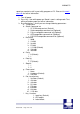
MAN607-S 1 SYSTEM DESCRIPTION This reference manual describes the specifications, functions, and operating procedures for the PRN607-S Interface Board. The PRN607-S is an interface board for the FTP607MCLxxx series printer mechanisms. This reference manual also describes the print operation of the FTP607MCLxxx. Read this reference manual thoroughly before using the PRN607-S. PRN607-S is designed for the following Fujitsu printers: FTP627MCLxxx FTP637MCLxxx PRN607-S consists of an interface board.
MAN607-S (a) To connect or remove the connector, always turn off the power in advance. If the connector is connected or removed while the power to the printer is on, errors may occur. (b) The connector of each cable must be correctly locked and connected. The connector at the head side has no lock feature. Check that the connector at the head side is completely inserted. (c) To install the interface, carefully check each cable so that excessive force is not applied to each cable.
MAN607-S speed you need to install 3rd part utility program on PC. Please visit www.ifcom.com for further information. 1. Turn off power 2. Press Key 1 low while power up. Board is now in setting mode. Text will be printed on paper for further information 3. By activating key 1 and 2 you can change following parameters: a. Test printout b. Select Command set i. I/F-COM command set (Default) ii. Seiko compatible command set (Optional) iii. Fujitsu compatible command set (Optional) iv.
MAN607-S 4. Black mark detection 5. Paper near end function j. k. l. m. n. o. p. q. 28-03-2003 Key 2 function 1. Input key 2. LED output 3. Label detect 4. Black mark detection 5. Paper near end function IRDA i. Enabled (Optional) ii. Disabled Auto form feed i. 0 sec. ii. 1 sec. iii. 2 sec. (Default) iv. 3 sec. v. 4 sec. vi. 5 sec. Form feed length i. 0 mm ii. 1 mm iii. 2 mm iv. 5 mm v. 10 mm vi. 20 mm vii. 30 mm viii. 50 mm (Default) Grey scale printing i. On (optional) ii. Off Acceleration i.
MAN607-S vi. 5 vii. 6 viii. 7 ix. 8 x. 9 r. Burn strobe light i. -1 ii. -2 iii. -3 iv. -4 v. -5 vi. -6 vii. -7 viii. -8 ix. -9 Settings will be effective upon turn off and on. 2.6 Serial Input/Output If BUSY control is selected: When 236 bytes of data have been stored in the input buffer, the SBUSY signal becomes high to request that the computer temporarily stop sending data.
MAN607-S (b) The data when executing the Vhead voltage response (c) The data when the error status response is set and an error occurs (d) The data when executing the execution response request (e) The data when executing the remaining RAM capacity response (f) The data when executing the environmental temperature response At the selection of serial input, data (b) through (f) is transferred according to the transfer conditions, which are set using the function switches.
MAN607-S Framing error (?: 3F16) If the input data cannot be printed correctly and instead “!” or “?” is printed, the transmission conditions between the host device and the PRN607-S most likely does not match. If this happens, adjust the conditions so that they match. 2.6.3 Thermal Head Control Data Transfer to the Thermal Head The PRN607-S transfers one dot line of data at 4 Mbps synchronized with the CLOCK signal.
MAN607-S 64 through 256 dots can, however, are set using the command for setting the number of dynamic division dots. When the maximum number of activated dots is 128 dots, and all of the dots are driven, as shown in 2.6.6 Head Control Circuit The PRN607-S has a function for measuring the resistance of the thermal head connected to the FTP607MCLxxx. The PRN607-S measures the resistance of the thermal head and detects the errors at initialisation.
MAN607-S 3 Specifications Default settings Interface Serial RS232C, USB or IRDA 115.200 baud, 8 data bit, none parity, 1 stop bit, hardware handshake. Baud rate can be changed by software. Data format serial USB Printer class specification. Data format USB http://www.usb.org/developers/docs IRDA (Ircomm specifications) Data format IRDA http://www.irda.org/standards/pubs/ircomm10.pdf Command set I/F-COM Transmission to host Requested status etc.
MAN607-S 4 Function 4.1 General Notice, when data is sent from the external equipment to the printer controller, all data has to be sent as binary file. If data is being sent as a character file, and some data in the file is equal to EOF, the rest will not be received. 4.2 Serial communication. Standard communication is; Baud rate; 115.200 Baud Data bits = 8 Stop bits = 1. Parity = None Flow control = Hardware handshake Baud rate can be changed. See setting for more information. 4.3 USB communication.
MAN607-S 4.5 Firmware upgrade. If firmware needs to be changed, alternative firmware can be downloaded. Please contact I/F-COM for firmware upgrade or changes. The steps to download an alternative firmware in DOS are the following. These steps only work for a serial connection, look further down how to do it with USB. 1. Power the system off. 2. Disconnect printer. 3. Short circuit the pins “upgrade firmware” 4. Turn on printer 5.
MAN607-S 4.7 Character design The following figures describes the design of different types of characters (small): 4.7.1 Normal Character. 4.7.2 Low Character 4.7.3 Underline When underline characters are printed the last line in the character matrix will be marked. 4.7.4 Bold When bold characters are printed the character is or with itself shifted right.
MAN607-S 4.7.5 Reverse When reverse characters are printed the character matrix will be negated. 4.7.6 Italic. When Italic characters are printed every line will be shifted the following number of dots to the right: (Line number from bottom)/4 4.7.7 Font sizes.
MAN607-S 4.8 Printer commands I/F-COM simple command set is default command set however optional command set can be downloaded. See appendix for additional information. 4.9 I/F-COM simple command set. The following commands are use when communicating with the printer controller. All other commands is ignored 4.9.1 Small Font [Name] [Format] [Description] 4.9.2 Low Font [Name] [Format] [Description] 4.9.3 Narrow Font [Name] [Format] [Description] 4.9.
MAN607-S 4.9.5 Wide Font [Name] [Format] [Description] 4.9.6 High Font [Name] [Format] [Description] 4.9.7 Large Font [Name] [Format] [Description] 4.9.8 Xlarge Font [Name] [Format] [Description] 4.9.9 Line Feed [Name] [Format] [Description] Wide Font (32x28) ASCII EOT Hex 04 Decimal 4 Chooses wide font from the current print position. High Font (16x56) ASCII ENQ Hex 05 Decimal 5 Chooses high font from the current print position.
MAN607-S [Notes] The barcode 39 must start and end with the character ‘*’. This character is the start and stop character in barcode 39, and the ‘*’ can only be used as start and end character. If the barcode length exceeds the paper size the last barcode character will not be written as barcode. In that case the barcode cannot be read because the last character will not be ‘*’ 4.9.11 Feed Forward [Name] [Format] [Description] 4.9.12 Reverse off [Name] [Format] [Description] 4.9.
MAN607-S [Description] 4.9.16 Bold off [Name] [Format] [Description] 4.9.17 Bold on [Name] [Format] [Description] This command will switch on underline printing Bold off ASCII DC2 Hex 12 Decimal 18 This command will switch off bold printing Bold on ASCII DC3 Hex 13 Decimal 19 This command will switch on bold printing 4.9.18 Italic off [Name] Italic off [Format] ASCII DC4 Hex 14 Decimal 20 [Description] This command will switch off italic printing 4.9.
MAN607-S 4.9.21 Request Software version [Name] Request software version [Format] ASCII ETB Hex 17 Decimal 23 [Description] When the printer controller receives this byte the software version will be transmitted. This command can be treated even if buffer is full. 4.9.22 Request Status [Name] [Format] Request status ASCII CAN Hex 18 Decimal 24 [Description] When the printer controller receives this byte a status byte will be transmitted. This command can be treated even if buffer is full.
MAN607-S 4.9.24 Request Temperature [Name] Request Temperature [Format] ASCII SUB Hex 1A Decimal 26 [Description] When the printer controller receives this byte the digital value of the head temperature will be transmitted. This command can be treated even if buffer is full 4.9.25 Sub command set [Name] Sub command set [Format] ASCII ESC n Hex 1B n Decimal 27 n [Range] n: [-128;127] [Description] The n is the commands in the sub-set. 4.9.
MAN607-S 4.9.28 Automatic sending status [Name] [Format] [Description] Automatic sending status ASCII ESC a Hex 1B 61 Decimal 27 97 When this command is sent once, then the board will transmit the status every time that it change state. 4.9.29 Stop sending automatic status [Name] Stop sending automatic status [Format] ASCII ESC b Hex 1B 62 Decimal 27 98 [Description] When this command is sent then it will turn off transmitting status. 4.9.30 Color/Grey scale graphic [Name] [Format] [Description] 4.9.
MAN607-S 4.9.32 Save data to board [Name] [Format] [Description] 4.9.33 Change dot size [Name] [Format] [Description] 4.9.34 Change form feed length [Name] [Format] [Description] 4.9.35 Change baud rate [Name] [Format] [Description] 4.9.36 Change form feed time [Name] [Format] 28-03-2003 Page 4-27 of 53 Save data to board ASCII ESC e Hex 1B 65 Decimal 27 101 This command saves all settings to flash.
MAN607-S [Description] 4.9.37 Feed Paper [Name] [Format] [Range] [Description] N represents the time between that the board registry incoming paper, and to it starts feed the auto form feed length. The time is calculated as n * 50msec. The default setting is 2 seconds. The value is saved to flash. Legal values for n are between 1 and 255. Feed Paper ASCII GS n Hex 1D n Decimal 29 n n: [-128;127] When the printer controller receives this command the paper will be fed n-dot lines.
MAN607-S 4.9.40 Bar code height setting. [Name] Bar code height setting [Format] ASCII ESC h n Hex 1B 68 n Decimal 27 104 n [Range] 1<=n<=255 [Default] n=60 [Description] Parameter n specifies the height of a bar code in dots. 4.9.41 Bar code printing [Name] [Format] [Description] Bar code printing ASCII ESC k m n d1 to dn Hex 1B 6B m n d1 to dn Decimal 27 107 m n d1 to dn Parameter m specifies the type of bar codes to be printed. Parameter n specifies no of barcode characters.
MAN607-S Code128 barcode table ‘d’ 0 1 2 3 4 5 6 7 8 9 10 11 12 13 14 15 16 17 18 19 20 21 22 23 24 25 26 27 28 29 30 31 32 33 34 35 36 37 38 39 40 41 42 43 44 45 46 28-03-2003 A Space ! “ # $ % & ‘ ( ) * + , . / 0 1 2 3 4 5 6 7 8 9 : ; < = > ? @ A B C D E F G H I J K L M N B Space ! “ # $ % & ‘ ( ) * + , .
MAN607-S 4.9.
MAN607-S Default: PAGELENGHT=150mm PAPEROFFSET=2mm BLACKMARK=120 (120/8=15mm) ESC+205+1+98+n n: Bit 0: if set the board will transmit ’B’ everytime paper is not detected at the paper detector. Bit 1: if set the Black Mark function is enable. Default n = 0. 4.9.43 Graphic data – non compressed [Name] Graphic data – non-compressed [Format] ASCII US d1,d2,..,dX Hex 1F d1,d2,..,dX Decimal 31 d1,d2,..
MAN607-S A very few lines cannot be compressed. These will if you try to compress them be longer than the non-compressed line. These must therefore be send as non-compressed data. 4.9.45 Escape sequences, overview. ESCAPE SEQUENCES, ASCII NUL SOH STX ETX EOT ENQ ACK BEL LF VT FF SO SI DLE DC1 DC2 DC3 DC4 NAK SYN ETB CAN EM SUB GS+n RS+n US+d1..
MAN607-S 5 Maintenance 5.1 Daily use Printer and interface board must be switch off while in idle mode. 5.2 Store/Transport The product has to be stored under ESD safe conditions, and to be packed safely during transportation.
MAN607-S 6 Specifications 6.1 Electrical Data Voltage: Current: 18-26VDC Maximum head current:Numbers of active dots * Vhead 1.500+/-15% Maximum motor current: Power up sequence: Power down sequence: 1.000mA max. 10 msec. 10 – 90% Voltage applied max. 10 msec. 90 – 10% Voltage applied 6.2 Mechanical Data Dimensions: Length, width, height: 77 mm* 50 mm * max. 15 mm Including connectors. Vibration: 100G XYZ Shock: 100G XYZ 6.
MAN607-S 6.5 Temperature Test Temperature shock: (no voltage applied) -28°C to +100°C at 1 sec. 100 times: no damage.
MAN607-S 6.6 Connector Pin Assignment 6.6.1 Thermal Head connector Thermal Head connector CN1: CF04301V000 Connector for use with following mechanisms: FTP627MCLxxx Pin Function Pin Function 1 PHK 16 GND 2 +5V 17 GND 3 P1 18 GND 4 GND 19 /ST2 5 SW 20 /ST1 6 VH 21 LAT 7 VH 22 CLK 8 VH 23 NC 9 DI 24 VH 10 /ST3 25 VH 11 +5V 26 VH 12 TI1 27 /MB 13 GND 28 MB 14 GND 29 /MA 15 GND 30 MA 6.6.
MAN607-S Pin Function Pin Function 1 PHK 16 GND 2 +5V 17 GND 3 P1 18 GND 4 GND 19 TI 5 SW 20 /ST2 6 VH 21 /ST1 7 VH 22 LAT 8 VH 23 CLK 9 DI 24 VH 10 /ST3 25 VH 11 /ST4 26 VH 12 +5V 27 /MB 13 GND 28 MB 14 GND 29 /MA 15 GND 30 MA 6.6.3 IRDA connector IRDA connector CN3: B4B-ZR Mating connector part number: TBA Pin 1 Function +5V 2 3 TX RX 4 GND 6.6.
MAN607-S The paper near end status, can be seen on the LED on the aux connector, it can be reading through the status command, and if a driver is used, then it can be reading in the port monitor: If paper jam is used, then will the printer stop printing if this signal is going low, the value of this bit can be seen on the LED on the aux output connector, it can be reading by a status request, or if a driver is used, then it can be reading by the port monitor. 6.6.
MAN607-S Function GND Vcoil, Max 24V Coil, max 1A Anode Cathode The LED will show these conditions LED Means Off No Error Flash 1Hz Paper near end Flash 2Hz Paper jam On Both paper jam and near end 6.6.8 Cutter connector Cutter connector CN5: B4B-KH-A Mating connector part number: TBA Pin Function 1 2 3 4 Sense GND /CUT CUT 6.6.
MAN607-S 6.
MAN607-S 7 Appendix 7.1 Seiko compatible command set 7.1.1 Escape sequences, overview. CR ESC+ ‘ J ’ +n ESC+ ‘ j ’ +n ESC+ ‘ 2 ’ ESC+ ‘ 0 ’ ESC+ ‘A’+n or ESC+ ‘3’+n n-dot ESC+ SP+n ESC+ ‘ s ’+nl+nr ESC+ ‘ U ’+n DC2+ ‘ Y’ +n ESC+ ‘ - ’ +n SO DC4 ESC+ ‘ W ’+n ESC+ ‘ w ’+n ESC+ ‘ I ’+n DC2+ ‘ F ’+n ESC+ ‘ t ’+n ESC+ ‘ & ’ + s + e+ ESC+ ‘ % ’ + n DC2+ ‘ D ’+n ESC+ ‘+’ + k1 + k2+ FS+ ‘ 2 ’ + k1 + k2+ ESC+ ‘ K ’ or FS+ ‘ & ’ ESC+ ‘ H’ or FS+ ‘.
MAN607-S DC3+ ‘ + ’ DC3+ ‘ - ’ Ruler Line ON Ruler Line OFF Print One Dot Line after Printing Line Buffer Data Ruler Line Buffer Clear Continuous Ruler Line Control Code Input DC3+ ‘ P ’ DC3+ ‘ C ’ DC3+ ‘ (’ 7.2 Fujitsu compatible command set 7.2.1 Escape sequences, overview.
MAN607-S FS 9+n FS C+n FS W+n GS < GS A+m+n GS E+n GS V+n+m GS e+n+m GS h+n GS k+m+n+[d]k GS w+n FS *+n1+n2+[n]k GS &+m+x+y1+y2+[n]k GS '+m+n FS E+n ESC V+n GS a+n FS r+n ESC EM+n ESC X+n+m 7.
MAN607-S [Function] The HT command moves the printing position to the tab position. [Code] [09]16 [09]10 [Explanation] 1. If the next horizontal tab position is not set, the HT command is ignored. 2. If the next horizontal tab position is outside the printing area, the printing position is shifted to the proper position by adding 1 to the printing area width. 3.
MAN607-S 5. If line spacing during printing/line-feeding is shorter than the character height, a length equal to the character height feeds the paper. 7.3.3 Forms feed [Name] Forms feed (new page) [Function] The FF command prints the data already contained in the print buffer, then sets the next-data receive position at the leftmost column on the next page. [Code] [0C]16 [12]10 [Explanation] (1) The FF command feeds paper by the specified page length.
MAN607-S 7.4 APS compatible command set 7.4.1 Escape sequences, overview.
MAN607-S Comments: Example: GS D n Description: Format: Comments: ESC v Description: Format: Comments: 28-03-2003 n=1 to 32: (Default n=5) Software programmable consumption (Dynamic division). The maximum number of black dots which are simultaneously heated is (n+1) x 8. In Default Mode, n = 5. n=5 Maximum black dots heated: (5+1)*8=48. Printer Peak consumption @5V: (0.3A (Stepper Motor) + 5*48/160) = 1.8A 160 Ohms is the dot resistance. Set print Intensity <1Dh> <44h> n=8Fh (127d) : (Default).
MAN607-S 7.5 ESC/POS compatible command set 7.6 Escape sequences, overview.
MAN607-S ESC i ESC p m t1 t2 ESC t n ESC u n ESC v ESC { n GS ! n G S $ nL nH GS * x y [d] x*y *8 GS / m GS : GS B n GS H n GS I n GS L nL nH GS P x y GS V m n GS W nL nH GS \ nL nH GS ^ r t m GS a n GS b n Partial cut Cash drawer Output Select character Code table Transmit peripheral device status Transmit paper sensor status Turns on/off upside-down printing mode Select character size Set absolute vertical print position in page mode Define download bit image Print downloaded bit image Start / end macro
MAN607-S 28-03-2003 Page 7-51 of 53
MAN607-S 7.
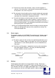
MAN607-S Example showing how to connect PRS600 to AUX Input connector CN5 on PRN607-S standard board.