English USER’S MANUAL 42”/50” WIDE PLASMA DISPLAY P42VHA10W/P42VHA10A/ P42HHA10W/P42HHA10A/ P50XHA10W/P50XHA10A/P50XHA10U/ P42VHA20W/P42VHA20A/P42VHA20U Contents Page Before Use • Safety Precautions ··································· E-2–E-3 • Features ····························································E-4 • Accessories ······················································ E-5 • Handy Tips ······················································· E-5 • Installation ·······························
SAFETY PRECAUTIONS IMPORTANT INFORMATION IMPORTANT The lightning flash with arrowhead symbol, within an equilateral triangle, is intended to alert the user to the presence of uninsulated “dangerous voltage” within the product’s enclosure that may be of sufficient magnitude to constitute a risk of electric shock to persons. CAUTION: TO PREVENT THE RISK OF ELECTRIC SHOCK, DO NOT REMOVE COVER (OR BACK). NO USER-SERVICEABLE PARTS INSIDE. REFER SERVICING TO QUALIFIED SERVICE PERSONNEL.
Power supply voltage: AC 100–125 V (42”10W, 42”U, 50”U Type: Included) AC 200–240 V (42”20W, 50”W Type: Included) AC 240 V (SAA TYPE) (42”A, 50”A Type: Included) E-3 English 12) Use only with the cart, stand, tripod, bracket, or table specified by the manufacturer, or sold with the apparatus. When a cart is used, use caution when moving the cart/apparatus combination to avoid injury from tip-over. 13) Unplug this apparatus during lightning storms or when unused for long periods of time.
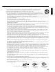
FEATURES Variety of input signals • The unit features four video and four S-video input terminals, and five component video terminals. • In addition to mD-sub terminal, the display also supports input of digital RGB signal input enabling DVI standard (HDCP*) high definition picture quality. • Depending on the model, the display supports video input for different color television systems as follows: NTSC, PAL, SECAM, PAL60, N-PAL, M-PAL, 4.43NTSC.
CHECKING ACCESSORIES One remote control Two AA batteries One user’s manual One power cable Two big ferrite cores Two small ferrite cores Manual (42”10W, 42”20U, 50”U Type) (42”20W, 50”W Type) (42”A, 50”A Type) HANDY TIPS • Viewing the screen constantly for extended periods can strain your eyes. Be sure to stay at a proper distance (at least 1.5 m or 5 feet (42”)/ 1.9 m or 6.3 feet (50”)) from the screen and to look occasionally away while working.
INSTALLATION To prevent the display’s internal components from overheating, make sure that the display is installed in a well-ventilated location. Be sure to use the optional stand, wall-mounting unit or the other unit when installing the display. Also, be also sure that your dealer performs the installation. See the appropriate instruction manual for more information on the installation hardware you select.
English PART NAMES AND FUNCTIONS DISPLAY SECTION – FRONT (Right section) 1 Power indicator lamp This lamp shows the state of the power supply. Lit (red): Stand-by Lit (green): Power ON Lit (orange): Power saving (DPMS: Power saving function) mode ON (See P. E-36.) Flashing (red): Malfunction (Flashes differently depending on the type of malfunction. See P. E-45 for more information.) 2 Remote control signal receiver Receives signals from the remote control.
PART NAMES AND FUNCTIONS (Continued) DISPLAY SECTION – LOWER PART Bottom (P42VHA10 type) Bottom (P42HHA10 type) Bottom (50”) Bottom (P42VHA20 type) 1 /I power switch When pressed while in the “OFF” state, the power indicator lamp lights and the display is placed in the “ON ” state, and the power can be turned “ON” or “OFF” by the remote control or on the control panel of the display.
English 6 External speaker output terminal (EXT SP) Connect this terminal to the optionally available speaker. When connecting a cable, attach a ferrite core to the cable. (See P. E-13.) *See the speaker instruction manual for more information. 7 Audio1 input terminal (AUDIO1 INPUT) 8 Audio2 input terminal (AUDIO2 INPUT) 9 Audio3 input terminal (AUDIO3 INPUT) Connect this terminal to the sound output terminal of your VCR, etc. (See P.E-36 for the selection of audio input for video input.
PART NAMES AND FUNCTIONS (Continued) REMOTE CONTROL For details, see page 1 . 2 MUTE button button Switches between power ON and standby state. 3 DISPLAY OFF button 4 PICTURE MODE button 7 RGB input mode selector button [RGB 1 – 2] Selects RGB 1 – 2. 8 RGB3/VIDEO4 input mode selector button [RGB3/VIDEO4] Selects VIDEO4. 9 Video input mode selector button [VIDEO 1 – 3] Selects VIDEO 1 – 3. – Use this button to display a desired menu for adjusting the picture.
English USING THE REMOTE CONTROL PUTTING BATTERIES IN THE REMOTE CONTROL 1 To remove the cover, slide it outwards while pressing it down. 2 Place two AA batteries in the remote control. Make sure that the batteries are properly oriented. 3 Close the cover until it snaps into place. PRECAUTIONS To prevent malfunction, be sure not to apply any form of severe shock to the remote control.
USING THE REMOTE CONTROL (Continued) EFFECTIVE RANGE FOR THE REMOTE CONTROL Point the remote control at the display’s signal receiver when using it. Make sure that there are no obstacles between the remote control and the display’s signal receiver. Upper 20° 20° Lower Display – side Left 30° 30° Right 5 m (Front) Display – front Information The remote control may not function properly if you use a high-frequency fluorescent lamp.
Be sure to turn OFF the power to the display and external equipment before making any connections. No cables are supplied with the display for connection to external equipment. The type of cable to be used varies depending on the PC model. Contact your dealer for more information. RECEPTACLE Make sure that the power cable’s grounding wire is grounded. The display comes with a 3-prong power plug; one prong is connected to the grounding wire.
CONNECTING THE DISPLAY TO EXTERNAL EQUIPMENT (Continued) EXAMPLE OF CONNECTION TO EXTERNAL COMPONENTS Speaker Display Speaker (optional) Remote control VCR or other external components See P.
English VCR • Connect the video signal cable to either the S-video input terminal or the video input terminal. To audio outputs To video output To S-video output To audio inputs To S-video input To video input Bottom of Display (Ex.: P42VHA10) Note • Unplug the power cord from the AC outlet before you connect external components. • Also refer to the instructions for the component to be connected. • When inputting audio, connect to the terminals corresponding to the used video input or RGB input.
CONNECTING THE DISPLAY TO EXTERNAL EQUIPMENT (Continued) DVD PLAYER • Connect the video signal cable to the component video input terminal, S-video input terminal, or the video input terminal. • If the component to be connected is equipped with component video output terminal, it is recommended to connect to the component video terminal.
• As the cable for connecting a PC differs with the PC model, please consult your dealer for information on the right cable to purchase. • The PC can be connected to either the front side or the rear side, whichever is most convenient. To RGB output (DVI-D) To RGB output (mD-sub) To RGB2 input (mD-sub) To audio output To audio input To RGB1 input (DVI-D) Bottom of Display (Ex.: P42VHA10) Note • Unplug the power cord from the AC outlet before you connect external components.
BASIC OPERATIONS TURNING THE POWER ON AND OFF 1 Press /I to the left at the bottom of the display to the ON state. The power lamp lights up. 2 Press 3 Press on the remote control. The color of the power lamp changes from “Red” to “Green”. – or – or . Select the video mode to be input. Press when the power is ON. The color of the power lamp changes from “Green” to “Red” and the power turns “OFF”. * You can also use the buttons on the display’s control panel to perform these steps.
English ADJUSTING THE VOLUME Press the Volume button Press to increase the volume. Press to reduce the volume. Any value between 0 and 40 can be selected. * Note that the volume level remains stored even when you turn OFF the power. When the volume adjustment button is pressed Muting the sound Press . The sound is removed. Press again to restore the sound to the original level. The mute mode can also be released by pressing the volume buttons.
SELECTING INPUT MODE VIDEO INPUT MODE 1 Press the – buttons to select the input mode. You can select from VIDEO1 mode to VIDEO4 mode. The video modes corresponding to each input terminal are as follows. • VIDEO1: Video Video1 mode • VIDEO2: S-video • VIDEO3: Component video • VIDEO4: Component video * For selection of the input terminal, see “SETTING THE INPUT TERMINALS” on P. E-35. * You can also use the buttons on the display’s control panel to perform these steps.
English OTHER BASIC OPERATIONS CONVENIENT FUNCTIONS On-screen information (DISPLAY) Press . The mode is indicated on the screen for 5 seconds. Picture Mode (PICTURE MODE) Press . This button can be used to switch the picture mode. In the picture mode, you can switch between the set status and the fine mode. * For the picture mode settings, see “Setting Picture Mode (P. E-26)”. Picture Memory (PICTURE MEMORY) Press . This button can be used to recall the settings of the picture memories 1 – 8.
WATCHING PICTURES ON THE WIDE SCREEN SWITCHING BETWEEN SCREEN SIZES 1 Press 2 Press to select a desired picture mode. . The currently selected mode will appear. Each time you press , a different picture mode appears. The sequences used are as follows: Normal mode When you are in a Video or S-video input mode When you are in a Comp.video input mode When you are in an RGB input mode Wide1 mode * You can also use the buttons on the display’s control panel to perform these steps.
English SCREEN SIZE Normal Displays pictures of normal size (i.e., a 4:3 aspect ratio). Auto The screen size changes automatically in accordance with the contents of image software you use. Wide1 Displays natural-looking pictures of standard size on the wide screen.
ADJUSTMENT MENU ADJUSTMENT MENU MENU PICTURE Contrast POSITION/SIZE Brightness AUDIO Color FEATURES Tint FACTORY DEFAULT Sharpness Picture Mode PrecisionSetting Luminance Noise Reduction * Black Level Picture Memory Colour Temp. Position Size Can be set when Fine is selected as the Picture Mode. User Colour Temp. *: for other than RGB Treble Bass Balance Loudness Adjustment Dot Clock for RGB2 Function Clock Phase for RGB2 On Screen Menu Clamp Position for RGB2, Comp.
English ADJUSTING PICTURES (PICTURE MENU) BASIC OPERATIONS [EX.: ADJUSTING TINT (Tint)] You can make changes to all picture adjustment options in the PICTURE Menu. The changes you make will be stored for a selected input mode. Therefore, you need to select a desired input mode before making any changes. 1 Press 2 Press . The main menu screen will appear. or to select “PICTURE”.
ADJUSTING PICTURES (PICTURE MENU) (Continued) • Contrast, brightness, color darkness, tint, and picture sharpness are adjusted as shown in the following chart. Select the item with , and then adjust with . Finally, press to implement the adjustments.
English • Setting Noise Reduction (Noise Reduction) Can select the noise reduction setting corresponding to the noise level of the input signal. Each time you press or ,one of the available choices appears in the following sequence: Off: Noise reduction does not function. Min.: Weak setting Std.: Standard setting Max.: Strong setting Press to store. *Some type of signal can not be selected. • Storing the setting of PICTURE (Picture Memory) Stores 8 patterns of adjustments set by PICTURE.
ADJUSTING SCREEN POSITION AND SIZE (POSITION/SIZE MENU) BASIC OPERATION [EX.: ADJUSTING HORIZONTAL DIRECTION OF SCREEN POSITION] You can make changes to all screen adjustment options in the POSITION/SIZE Menu. The changes you make will be stored for the selected input mode. Therefore, you need to select a desired input mode before making any changes. 1 Press 2 Press . The main menu screen will appear. or to select “POSITION/SIZE”.
English Adjusting Screen Position (Position) Horizontal position (Horizontal) : Moves screen to the right. : Moves screen to the left. → → “Position” adjustment screen Vertical position (Vertical) : Moves screen up. → : Moves screen down. → Press to store. Adjusting Screen Size (Size) Screen width (Width) : Increases width. : Reduces width. → → “Size” adjustment screen Screen height (Height) Press : Increases height. → : Reduces height. → to store.
ADJUSTING AUDIO (AUDIO MENU) BASIC OPERATION [EX.: ADJUSTING VOLUME BALANCE (Balance)] You can make changes to all sound adjustment options in the AUDIO Menu. The changes you make will be stored for the selected input mode. Therefore, you need to select a desired input mode before making any changes. 1 2 Press . The main menu screen will appear. Press or to select “AUDIO”.
English Adjusting Treble (Treble) Any value between -6 and +6 can be selected. : Stronger treble : Weaker treble Adjusting Bass (Bass) Any value between -6 and +6 can be selected. AUDIO Menu screen : Stronger bass : Weaker bass Adjusting Volume Balance (Balance) Any value between -10 and +10 can be selected.
OTHER ADJUSTMENTS (FEATURES MENU) BASIC OPERATION [EX.: SELECTING LANGUAGE (Language)] You can make the following changes in the FEATURES Menu. 1 2 Press . The main menu screen will appear. Press or to select “FEATURES”. Each time you press or , one of the available menus appears in the following sequence: PICTURE POSITION/SIZE AUDIO “FEATURES” selected in the main menu screen FEATURES FACTORY DEFAULT The FEATURES Menu screen will appear. 3 Press or Screen Menu”.
Adjustment : Can make a fine adjustment of pictures such as Dot Clock, Clamp Position. Function : Allows setting of 24-frame mode. (See P. E-34.) English • FEATURES setup screen has the following 5 options. On Screen Menu : Can make a display setting such as OSD, Language. (See P. E-34.) Input Terminal : Can make an input terminal setting such as Video Input. (See P. E-35.) Others : Can make other settings. (See P. E-36–E-38.
OTHER ADJUSTMENTS (FEATURES MENU) (Continued) FUNCTION • Displaying the optimum movie pictures (24 Frame Mode) for Video Can make the optimum display of 24 frames/second signals such as movie pictures. Each time you press or , one of the available choices appears in the following sequence: Off On On : Displays the optimum movie pictures. Off : Displays normal pictures. Press to store. * Some type of signal can not be selected.
English SETTING THE INPUT TERMINALS • Selecting Video Mode (Video Input) You can use this option to select the desired video mode of pictures it will receive to the Video Input terminal. Each time you press or , one of the available modes appears in the following sequence: Auto1: Automatically selects NTSC, PAL and SECAM. Auto2: Automatically selects NTSC and M-PAL. Other than Auto: You need to select a system appropriate to the input signal. Press to store.
OTHER ADJUSTMENTS (FEATURES MENU) (Continued) OTHER SETTINGS DPMS for other then RGB1 You can use this option to select the amount of time before the DPMS function starts. DPMS (which stands for “display power management signaling”) allows the display to maintain an automatic power saving function. This function causes on-screen information to disappear until the next input operation, if the power is ON and the display has not received any signals for the predetermined period of time.
for RGB English • Minimizing phosphor burn-in (Screen Orbiter) You can use this option to move the screen position to minimize phosphor-induced “burn-in”. Follow the steps below. (1) Select “Screen Orbiter” and press . The “Screen Orbiter” setting screen will appear. (2) Press or to select “Mode/Time”. (3) Select a desired pattern. Each time you press or , one of the available choices appears in the following sequence: “Screen Orbiter” setting screen Off: Disables Screen Orbiter.
OTHER ADJUSTMENTS (FEATURES MENU) (Continued) • Specifying RGB Input Signal (Code Setting) for RGB2 You can use this option to specify and display the type of RGB input signal by code number. Each time you press or , one of the available choices appears in the following sequence: Manual Auto Auto: Automatically displays the input signal to the optimum. Manual: Selects RGB code number. Press “Code Setting” setting screen to store.
INITIALIZATION OF USER ADJUSTMENT VALUE (FACTORY DEFAULT) 1 Press 2 Press English You can restore the values of the adjustment/setting made in the MENU to factory settings. . The main menu screen will appear. or to select “FACTORY DEFAULT”. Each time you press or , one of the available menus appears in the following sequence: PICTURE POSITION/SIZE AUDIO “FACTORY DEFAULT” selected in the main menu screen FEATURES FACTORY DEFAULT The FACTORY DEFAULT Menu screen will appear. 3 Press .
OPTIONS Wall-mounting unit 0° to 15° mounting angle P-WB4200 Hanging unit 0° to 15° mounting angle P-CT4200 Stand P-TT4200 Speaker P-SP4200 (for 42”) P-SP5000 (for 50”) (1 set of 2 speakers) Speaker Stand P-ST4200 (for 42”) P-ST5000 (for 50”) (1 set of 2 speakers stands) * When installing an option, make sure that all installation requirements for that option (as given in the relevant instruction manual) are met. * The colors of options do not match the display colors perfectly.
This display can store the latest four types of signals for RGB adjustment value. The fifth input signal will replace the adjustment value of the first input signal. To do this, select a desired signal and follow the instructions in “Adjusting Screen Position and Size” on P. E-28–E-29 to adjust the parameters. When you finish, the settings will be automatically stored. Thus, when the display receives that signal, pictures will be displayed in accordance with the settings you most recently selected.
SPECIFICATION Model P42VHA10W/P42VHA10A P42HHA10W/P42HHA10A Screen size 42" wide screen: 92.1 cm (W) x 51.8 cm (H) (105.7 cm diagonal) 36.3 inch (W) x 20.4 inch (H) (41.6 inch diagonal) 42" wide screen: 92.2 cm (W) x 52.2 cm (H) (106.0 cm diagonal) 36.3 inch (W) x 20.6 inch (H) (41.7 inch diagonal) Aspect ratio 16:9 (wide) Weight 28.5 kg / 62.8 lbs Outer dimensions 103.7 (W) x 64.2 (H) x 8.5 (D) cm 40.8 (W) x 25.3 (H) x 3.3 (D) inch Power supply 110–240 VAC 50/60 Hz Current rating 3.1–1.
P50XHA10W/P50XHA10A P50XHA10U Screen size 50" wide screen: 110.6 cm (W) x 62.2 cm (H) (126.9 cm diagonal) 43.5 inch (W) x 24.5 inch (H) (50.0 inch diagonal) Aspect ratio 16:9 (wide) Weight 45.0 kg / 99.2 lbs Outer dimensions 121.4 (W) x 72.8 (H) x 9.8 (D) cm 47.8 (W) x 28.7 (H) x 3.9 (D) inch Power supply 220–240 VAC 50/60 Hz 120 VAC 50/60 Hz Current rating 2.7–2.0 A 4.
SPECIFICATION (Continued) Model P42VHA20W/P42VHA20A Screen size 42" wide screen: 92.0 cm (W) x 51.8 cm (H) (106.0 cm diagonal) 36.2 inch (W) x 20.4 inch (H) (41.7 inch diagonal) Aspect ratio 16:9 (wide) Weight 29.5 kg / 65.0 lbs Outer dimensions 103.7 (W) x 64.2 (H) x 8.5 (D) cm 40.8 (W) x 25.3 (H) x 3.3 (D) inch P42VHA20U Power supply 220–240 VAC 50/60 Hz 120 VAC 50/60 Hz Current rating 1.8–1.5 A 4.
Precautions Cleaning the Cabinet and Remote Control Be sure to remove the power plug from the receptacle before cleaning the display. Be sure not to clean the display using a cloth dampened with volatile solvents, such as benzene or thinner. Such solvents can harm the display’s cabinet, the filter at the screen front, and the remote control. They can also cause paint to come off these sections. Use a soft cloth for cleaning.