
Datasheet


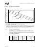

Intel® Xeon™ Processor with 800 MHz System Bus
22 Datasheet
At conditions exceeding absolute maximum and minimum ratings, neither functionality nor long-
term reliability can be expected. Moreover, if a device is subjected to these conditions for any
length of time then, when returned to conditions within the functional operating condition limits, it
will either not function, or its reliability will be severely degraded.
Although the processor contains protective circuitry to resist damage from static electric discharge,
precautions should always be taken to avoid high static voltages or electric fields.
NOTES:
1. For functional operation, all processor electrical, signal quality, mechanical and thermal specifications must
be satisfied.
2. Excessive overshoot or undershoot on any signal will likely result in permanent damage to the processor.
3. Storage temperature is applicable to storage conditions only. In this scenario, the processor must not receive
a clock, and no pins can be connected to a voltage bias. Storage within these limits will not affect the long-
term reliability of the device. For functional operation, please refer to the processor case temperature
specifications.
4. This rating applies to the processor and does not include any tray or packaging.
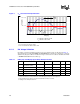
2.11 Processor DC Specifications
The processor DC specifications in this section are defined at the processor core (pads) unless
noted otherwise. See Section 5.1 for the Intel® Xeon™ processor with 800 MHz system bus pin
listings and Section 4.1 for signal definitions. Voltage and current specifications are detailed in
Table 9. For platform power delivery planning refer to Table 10, which provides V
CC
static and
transient tolerances. This same information is presented graphically in Figure 4.
BSEL[1:0] and VID[5:0] signals are specified in Table 12. The DC specifications for the AGTL+
signals are listed in Table 13. The DC specifications for the PWRGOOD input and TAP signal
group are listed in Table 14 and the Asynchronous GTL+ signal group is listed in Table 15.
Table 9 through Table 15 list the DC specifications for the processor and are valid only while
meeting specifications for case temperature (T
CASE
as specified in Section 6.0), clock frequency,
and input voltages. Care should be taken to read all notes associated with each parameter.
2.11.1 Flexible Motherboard Guidelines (FMB)
The Flexible Motherboard (FMB) guidelines are estimates of the maximum values the Intel®
Xeon™ processor with 800 MHz system bus will have over certain time periods. The values are
only estimates and actual specifications for future processors may differ. Processors may or may
not have specifications equal to the FMB value in the foreseeable future. System designers should
meet the FMB values to ensure their systems will be compatible with future Intel® Xeon™
processor with 800 MHz system bus.
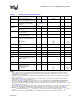
Table 8. Absolute Maximum and Minimum Ratings
Symbol Parameter Min Max Unit Notes
1,2
V
CC
Core voltage with respect to VSS -0.30 1.55 V
V
TT
System bus termination voltage with
respect to V
SS
-0.30 1.55 V
T
CASE
Processor case temperature See Section
6.0
See Section
6.0
°C
T
STORAGE
Storage temperature -40 85 °C 3, 4