
Datasheet


Intel® Xeon™ Processor with 800 MHz System Bus
74 Datasheet
3. Not 100% tested. Specified by design characterization.
4. The ideality factor, n, represents the deviation from ideal diode behavior as exemplified by the diode
equation: I
FW
= I
S
* (e
qVD/nkT
- 1)
Where I
S
= saturation current, q = electronic charge, VD = voltage across the diode, k = Boltzmann Constant,
and T = absolute temperature (Kelvin).
5. The series resistance, R
T
, is provided to allow for a more accurate measurement of the junction temperature.
R
T
, as defined, includes the pins of the processor but does not include any socket resistance or board trace
resistance between the socket and external remote diode thermal sensor. R
T
can be used by remote diode
thermal sensors with automatic series resistance cancellation to calibrate out this error term. Another
application that a temperature offset can be manually calculated and programmed into an offset register in
the remote diode thermal sensors as exemplified by the equation: T
error
= [R
T
* (N-1) * I
FW_min
] / [nk/q *ln N]
Where T
error
= sensor temperature error, N =sensor current ratio, k = Boltzmann Constant, q= electronic
charge.
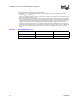
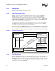
Table 27. Thermal Diode Interface
Pin Name Pin Number Pin Description
THERMDA Y27 diode anode
THERMDC Y28 diode cathode