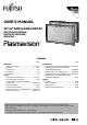
USER’S MANUAL 50”/61” WIDE PLASMA DISPLAY PDS5003W/PDS5004W/ PDS5003U/PDS5004U/ PDS6101W Contents Page Before Use • Safety Precautions ··································· E-2–E-3 • Features ····························································E-4 • Accessories ······················································ E-5 • Handy Tips ······················································· E-5 • Installation ······················································· E-6 Usage • Part Names and Functions ···
DECLARATION OF CONFORMITY according to EN45014 We Fujitsu General (U.K.) Co. Limited of Unit 150, Centennial Park, Centennial Avenue Elstree, Hertfordshire, WD6 3SG Manufacturer: Shinjyo Fujitsu General Limited 702-3 Kanazawa Shinjyo-shi Yamagata Japan declares under our sole responsibility that the product, Type: 50” PLASMA DISPLAY Model Name: PDS5003W to which this declaration relates are in conformity with the following standards; EMC: Safety: European Standards: a.
DECLARATION OF CONFORMITY according to EN45014 We Fujitsu General (U.K.) Co. Limited of Unit 150, Centennial Park, Centennial Avenue Elstree, Hertfordshire, WD6 3SG Manufacturer: Shinjyo Fujitsu General Limited 702-3 Kanazawa Shinjyo-shi Yamagata Japan declares under our sole responsibility that the product, Type: 50” PLASMA DISPLAY Model Name: PDS5004W to which this declaration relates are in conformity with the following standards; EMC: Safety: European Standards: a.
DECLARATION OF CONFORMITY according to EN45014 We Fujitsu General (U.K.) Co. Limited of Unit 150, Centennial Park, Centennial Avenue Elstree, Hertfordshire, WD6 3SG Manufacturer: Shinjyo Fujitsu General Limited 702-3 Kanazawa Shinjyo-shi Yamagata Japan declares under our sole responsibility that the product, Type: 61” PLASMA DISPLAY Model Name: PDS6101W to which this declaration relates are in conformity with the following standards; EMC: Safety: European Standards: a.
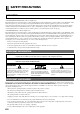
SAFETY PRECAUTIONS FCC NOTICE • PDS5003W/PDS5003U/PDS6101W: A Class A digital device This equipment has been tested and found to comply with the limits for a Class A digital device, pursuant to Part 15 of the FCC Rules. These limits are designed to provide reasonable protection against harmful interference when the equipment is operated in a commercial environment.
Do not place this product on an unstable cart, stand, or table. The product may fall, causing serious injury to a child or adult, and serious damage to the product. The product should be mounted according to the manufacturer’s instructions, and should use a mount recommended by the manufacturer.
FEATURES This display uses a plasma display panel and is only 9.8 cm (50”) /11.8 cm (61”) deep. With its high picture quality and performance, it is perfectly suited for multimedia applications. Variety of input signals • In addition to video, S-video, and RGB, signals, this display supports input of high-quality video signals such as DVD and HDTV.
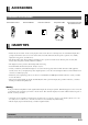
CHECKING ACCESSORIES One remote control Two AA batteries One user’s manual One power cable Two big ferrite cores and two small ferrite cores Manual (50”U,61”W Type) (50”W Type) HANDY TIPS • Pictures may become “burnt” into the screen phosphors if the screen is left on for extended periods. To ensure that the display has a prolonged service life, be sure to use a screen orbiter, white screen. This will ensure the same picture or pattern is not constantly displayed for long periods. (See P.E-38-39.
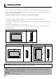
INSTALLATION To prevent the display’s internal components from overheating, make sure that the display is installed in a well-ventilated location. Be sure to use the optional desktop stand, ceiling-mounting unit, wall-mounting unit and other unit when installing this display. Also, be sure that your dealer performs the installation. See the appropriate instruction manual for more information on the installation hardware you select.
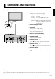
PART NAMES AND FUNCTIONS English Front (both 50" and 61") 1 Power indicator lamp This lamp shows the state of the power supply. Lit (red): Power OFF (stand-by) Lit (green): Power ON Lit (orange): Power saving (DPMS: Power saving function) mode ON Flashing (red): Malfunction (Flashes differently depending on the type of malfunction. See P. E-46 for more information.) 2 Remote control signal receiver Receives signals from the remote control. 3 Power button Turns the power ON or OFF (stand-by).
PART NAMES AND FUNCTIONS (Continued) Bottom (50”) Bottom (61”) 1 OFF/STD-BY switch OFF :The power indicator lamp goes off, and the power can’t be turned on by the power button. The power is partly supplied. STD-BY :The power indicator lamp lights red, and the power can be turned on or off by the power button. 2 RGB 2 input terminal (RGB 2 INPUT/mD-sub) Connect this terminal to the PC’s display (analog RGB) output terminal or decoder (digital broadcast tuner, etc.) output terminal.
Connect this terminal to the sound output terminal of your VCR, etc. (See P.E-37 for the selection of audio input for video input.) 0 RGB 3 synchronization switch (SYNC SW TTL/ANALOG (75 Ω)) This switch is used to terminate horizontal (H) terminal and vertical (V) terminal, out of RGB3 input terminals, with 75 Ω . TTL : Does not terminate. ANALOG (75 Ω): Terminates.
PART NAMES AND FUNCTIONS (Continued) Description of Input Terminals DVI-D terminal (RGB 1 INPUT/DVI-D) RGB2 input terminal (RGB2 INPUT/mD-sub) RS-232C terminal (RS-232C) E-10 Pin No. Input signal Pin No. 1 9 Red Input signal — 2 Green 10 Ground 3 Blue 11 — 4 — 12 — 5 Ground 13 Horizontal synchronization 6 Ground 14 Vertical synchronization 7 Ground 15 — 8 Ground Frame Ground Pin No.
1 Power ON button [POWER ON] ➝ (See P. E-16.) 1 2 2 Power OFF button [POWER OFF] ➝ (See P. E-16.) 3 5 4 3 RGB input mode selector button [RGB] ➝ (See P. E-17.) 4 Video input mode selector button [VIDEO] ➝ (See P. E-17.) 6 5 Wide screen selector button [WIDE] ➝ (See P. E-18–E-19.) 6 Menu button [MENU] ➝ (See P. E-20–E-41.) 7 8 9 Use this button to display a desired menu for adjusting the picture. ➝ (See P. E-16.) 7 Volume adjustment buttons [VOL +/-] Adjust the volume.
USING THE REMOTE CONTROL PRECAUTIONS To prevent malfunction, be sure not to apply any form of severe shock to the remote control. To prevent malfunction or deformation, be sure not to allow the remote control to become wet; also, keep it away from hot locations or heating equipment. Be sure not to clean the remote control using a cloth dampened in any volatile solvent, such as benzene or thinner.
Be sure to turn OFF the power to the display and external equipment before making any connections. No cables are supplied with the display for connection to external equipment. The type of cable to be used varies depending on the PC model. Contact your dealer for more information. RECEPTACLE Make sure that the power cable’s grounding wire is grounded. The display comes with a 3-prong power plug; one prong is connected to the grounding wire.
CONNECTING THE DISPLAY TO EXTERNAL EQUIPMENT(Continued) (50”) VIDEO INPUT S-VIDEO INPUT RS-232C RGB1 INPUT (DVI-D) RGB2 INPUT (mD-sub) To video To S-video To RS-232C To display To display output output output (digital RGB) (analog RGB) terminal terminal terminal output output terminal terminal E-14 COMPONENT VIDEO INPUT (color difference input) / RGB3 INPUT AUDIO1 INPUT AUDIO2 AUDIO3 INPUT INPUT To sound To sound To sound output output output terminal terminal terminal EXT SP POWER INPUT To To
English (61”) VIDEO INPUT POWER INPUT To receptacle COMPONENT VIDEO INPUT (color difference input) / RGB3 INPUT To color difference output terminal / To display (analog RGB) output terminal RGB2 INPUT (mD-sub) RGB1 INPUT (DVI-D) To display To display (analog RGB) (digital RGB) output output terminal terminal RS-232C S-VIDEO INPUT AUDIO1 AUDIO2 AUDIO3 INPUT INPUT INPUT To RS-232C To S-video To video To sound To sound To sound output output output output output output terminal terminal terminal te
BASIC OPERATIONS TURNING ON THE POWER 1 Select the OFF/STD-BY at the STD-BY switch of the display. When you do so, the power indicator lamp turns red. (This applies only to 50”display.) 2 Press control. on the remote When you do so, the power indicator lamp turns green. 3 Press or to select a desired input mode. * You can also use the switches on the display’s control panel to accomplish these steps. TURNING OFF THE POWER Press when the power is ON. The power indicator lamp turns red.
English SELECTING INPUT MODE VIDEO INPUT MODE 1 Press mode. to select a desired input Each time you press , a different input mode appears. The sequence is as follows: Video: S-video: Displays pictures from equipment connected to the Video terminal. S-video mode Displays pictures from equipment connected to the S-video terminal. Comp.video: Displays pictures from equipment connected to the component video input terminal. * When RGB-PC is selected in BNC Input mode, Comp.
WATCHING PICTURES ON THE WIDE SCREEN SWITCHING BETWEEN SCREEN SIZES 1 Press . The currently selected mode will appear. 2 Press to select a desired picture mode. Each time you press , a different picture mode appears. The sequences used are as follows: Normal mode When you are in a Video or S-video input mode When you are in a Comp.video input mode When you are in an RGB input mode Wide1 mode * You can also use the switches on the display’s control panel to accomplish these steps.
English SCREEN SIZE Normal Displays pictures of normal size (i.e., a 4:3 aspect ratio). Auto The screen size changes automatically in accordance with the contents of image software you use. Wide1 Displays natural-looking pictures of standard size on the wide screen.
HOW TO USE MENUS SELECTING OPTIONS IN A MENU Use the [MODE] button on the display or 1 Press and on the remote control to select a desired input mode. . The main menu screen will appear. 2 Press or Each time you press to switch between sub-menus. or Ex.: “PICTURE” selected in the main menu screen , one of the available menus appears. The corresponding menu screen will appear. 3 Press or to select an option for adjustment/setup.
Operation English Option Function (1) Contrast Adjusts picture contrast. : Higher contrast : Lower contrast -30 to +30 (2) Brightness Adjusts screen brightness. : Brighter screen : Darker screen -60 to +60 (3) Color Adjusts color darkness. : Darker colors : Lighter colors -60 to +60 (4) Tint Adjusts tint. : More greenish tint : More purplish tint Video, S-video: -30 to +30 Comp.video, RGB-Video, RGBPC, Decoder : -60 to +60 (5) Sharpness Adjusts picture sharpness.
HOW TO USE MENUS (Continued) USING THE AUDIO MENU When you finish selecting a desired option in the AUDIO menu screen, press . When you do so, the adjustment screen for that option appears. Press or to select option and press or to make adjustment. Press to store. (See P. E-30–E-31.) The adjustments you make will be stored for each audio input terminal. *Audio Input menu will not be displayed when "No Audio" is selected. (See P. E-37.
English On Screen Menu screen Others(1/2) Menu screen Input Terminal Menu screen Adjustment Menu (See P. E-32–E-33.) Option Function Operation Range/Setting (1) Dot Clock (for RGB2, RGB3) Adjusts the dot clock. Eliminates blur when the optimum value is selected with or . -60 to +60 (2) Clock Phase (for RGB2, RGB3) Adjusts clock phase. Eliminates blur when the optimum value is selected with or .
HOW TO USE MENUS (Continued) Input Terminal Menu(See P. E-32, E-35–E-36.) Option Function Operation Range/Setting (1) Video Input (for Video) Selects video mode. Use or for switching. Auto/NTSC/PAL/SECAM/ PAL60/N-PAL/M-PAL/ 4.43NTSC (2) S-video Input (for S-video) Selects video mode. Use or for switching. Auto/NTSC/PAL/SECAM/ PAL60/N-PAL/M-PAL/ 4.43NTSC (3) BNC Input Selects BNC Input signal. Display BNC Input screen and press or to select an option. Use or for switching. Select Comp.
Function Operation Range/Setting (4) Screen Orbiter (for RGB) Sets up screen orbiter. Display the “Screen Orbiter” adjustment screen and use or to select an option. Use or to switch between available choices for the selected option. Mode/Time Off (disabled) Time (every 1 hr) Mode (every time mode is switched) Moving area Min.(moves in small range) Std.(moves in moderate range) Max. (moves in wide range) (5) Input Priority Specifies input mode of highest priority. Use or for switching.
ADJUSTING PICTURES (PICTURE MENU) BASIC OPERATIONS [EX.: ADJUSTING TINT (Tint)] You can make changes to all picture adjustment options in the PICTURE Menu. The changes you make will be stored for a selected input mode. Therefore, you need to select a desired input mode before making any changes. 1 Press . The main menu screen will appear. 2 Press or to select “PICTURE”.
English • Adjusting Contrast (Contrast) Any value between -30 and +30 can be selected. : Higher contrast : Lower contrast Press to store. • Adjusting Screen Brightness (Brightness) Any value between -60 and +60 can be selected. : Brighter screen : Darker screen Press to store. • Adjusting Color Darkness (Color) Any value between -60 and +60 can be selected. : Darker colors : Lighter colors Press to store.
ADJUSTING SCREEN POSITION AND SIZE (POSITION/SIZE MENU) BASIC OPERATION [EX.: ADJUSTING HORIZONTAL DIRECTION OF SCREEN POSITION] You can make changes to all screen adjustment options in the POSITION/SIZE Menu. The changes you make will be stored for the selected input mode. Therefore, you need to select a desired input mode before making any changes. 1 Press . The main menu screen will appear. 2 Press or to select “POSITION/SIZE”.
English Adjusting Screen Position (Position) Horizontal position (Horizontal) : Moves screen to the right. : Moves screen to the left. → → “Position” adjustment screen Vertical position (Vertical) : Moves screen up. → : Moves screen down. → Press to store. Adjusting Screen Size (Size) Screen width (Width) → : Increases width. → : Reduces width. “Size” adjustment screen Screen height (Height) : Increases height. → : Reduces height. → Press to store.
ADJUSTING AUDIO (AUDIO MENU) BASIC OPERATION [EX.: ADJUSTING VOLUME BALANCE (Balance)] You can make changes to all sound adjustment options in the AUDIO Menu. The changes you make will be stored for the selected input mode. Therefore, you need to select a desired input mode before making any changes. 1 Press . The main menu screen will appear. 2 Press or to select “AUDIO”.
Each audio input English Adjusting Treble (Treble) Any value between -6 and +6 can be selected. : Stronger treble : Weaker treble Adjusting Bass (Bass) Each audio input Any value between -6 and +6 can be selected. “Treble” selected in the AUDIO Menu screen : Stronger bass : Weaker bass Adjusting Volume Balance (Balance) Each audio input Any value between -10 and +10 can be selected.
OTHER ADJUSTMENTS (FEATURES MENU) BASIC OPERATION [EX. : SELECTING LANGUAGE (Language)] You can make the following changes in the FEATURES Menu. 1 Press . The main menu screen will appear. 2 Press or to select “FEATURES”. Each time you press or , one of the available menus appears in the following sequence: PICTURE POSITION/SIZE AUDIO “FEATURES” selected in the main menu screen FEATURES FACTORY DEFAULT The FEATURES Menu screen will appear.
Adjustment : Can make a fine adjustment of pictures such as Dot Clock, Clamp Position. Function : Can make a function setting such as 24 Frame Mode, 3D Y/C. (See P. E-34.) English • FEATURES setup screen has the following 5 options. On Screen Menu : Can make a display setting such as OSD, Language. (See P. E-34.) Input Terminal : Can make an input terminal setting such as Video Input. (See P. E-35–E-36.) Others : Can make other settings. (See P. E-36–E-40.
OTHER ADJUSTMENTS (FEATURES MENU)(Continued) FUNCTION • Displaying the optimum movie pictures (24 Frame Mode) Can make the optimum display of 24 frames/second signals such as movie pictures. Each time you press or , one of the available choices appears in the following sequence: On Off On : Displays the optimum movie pictures. Off : Displays normal pictures. Press to store. *Some type of signal can not be selected.
English INPUT TERMINAL • Selecting Video Mode (Video Input) You can use this option to select the desired video mode of pictures it will receive to the Video Input terminal. or Each time you press , one of the available modes appears in the following sequence: Auto: Automatically selects NTSC, PAL and SECAM. Other than Auto: You need to select a system appropriate to the input signal. Press to store.
OTHER ADJUSTMENTS (FEATURES MENU)(Continued) INPUT TERMINAL • Selecting D-SUB Input (D-SUB Input) All modes You can use this option to select the signal system it will receive to D-SUB Input terminal. (1) Select D-SUB Input and press . D-SUB Input screen appears. (2) Select the signal system to receive.
All modes English • Selecting time before DPMS starts (DPMS) You can use this option to select the amount of time before the DPMS function starts. DPMS (which stands for “display power management signaling”) allows the display to maintain an automatic power saving function. This function causes on-screen information to disappear until the next input operation, if the power is ON and the display has not received any signals for the predetermined period of time.
OTHER ADJUSTMENTS (FEATURES MENU)(Continued) • Minimizing phosphor burn-in (Screen Orbiter) You can use this option to move the screen position to minimize phosphor-induced “burn-in”. Follow the steps below. (1) Select “Screen Orbiter” and press . The “Screen Orbiter” setting screen will appear. (2)Press or to select “Mode/Time”. (3)Select a desired pattern.
All modes English • Assigning Numbers to Displays (Monitor No.) When you use two or more displays, you can use a single remote control to control individual displays by assigning a unique number to each of the displays. Each time you press 0: or , one of the available numbers appears in the following sequence: You can normally control displays. You cannot control displays if you press any of [SHIFT 1] through [SHIFT 4].
OTHER ADJUSTMENTS (FEATURES MENU)(Continued) • Setting Exhibition Mode (Exhibition Mode) All modes You can use this option to display the enhanced contrast, which is most suitable for the use by unspecified persons. Each time you press On or , one of the available choices appears in the following sequence: Off On: Sets up Exhibition mode. Off: Sets up normal mode. Press to store. * In Exhibition mode, the display returns to the original setting in about 5 minutes even if the adjustment is changed.
INITIALIZATION OF USER ADJUSTMENT VALUE(FACTORY DEFAULT) 1 Press English You can restore the values of the adjustment/setting made in the MENU to factory settings. . The main menu screen will appear. 2 Press or DEFAULT”. to select “FACTORY “FACTORY DEFAULT” selected in the main menu screen Each time you press or , one of the available menus appears in the following sequence: PICTURE POSITION/SIZE AUDIO FEATURES FACTORY DEFAULT The FEATURES Menu screen will appear.
OPTIONS Wall-mounting unit Horizontal: 0° to 15° mounting angle (for horizontal) P-50WB01 (both 50" and 61") Hanging unit 0° to 15° mounting angle (variable) P-50CT01 (for horizontal) The pipe is not supplied with the ceiling-hanging unit, so consult your produce dealer.
This display can store the latest four types of signals for RGB adjustment value. The fifth input signal will replace the adjustment value of the first input signal. To do this, select a desired signal and follow the instructions in “Adjusting Screen Position and Size” on P. E-28–E-29 to adjust the parameters. When you finish, the settings will be automatically stored. Thus, when the display receives that signal, pictures will be displayed in accordance with the settings you most recently selected.
SPECIFICATION Model PDS5003W/PDS5003U/PDS5004W/PDS5004U PDS6101W Screen size 50" wide screen: 110.6 cm (W) x 62.2 cm (H) (126.9 cm diagonal) 43.5 inch (W) x 24.5 inch (H) (50.0 inch diagonal) 61" wide screen: 135.1 cm (W) x 76.0 cm (H) (155.0 cm diagonal) 53.2 inch (W) x 29.9 inch (H) (61.0 inch diagonal) Aspect ratio 16:9 (wide) 16:9 (wide) Weight 45.0 kg / 99.2 lbs 61.0 kg / 134.5 lbs Outer dimensions 121.2 (W) x 72.6 (H) x 9.8 (D) cm 47.7 (W) x 28.6 (H) x 3.9 (D) inch 145.2 (W) x 86.
English Regulation --- PDS5003W • EMC:FCC Part 15 Class A, ICES-003 Class A • CE Safety: EN60065 EMC: EN55022 1998, Class A EN61000-3-2 1995 EN61000-3-3 1995 EN55024 1998 EN61000-4-2 1995 EN61000-4-3 1996 EN61000-4-4 1995 EN61000-4-5 1995 EN61000-4-6 1996 EN61000-4-8 1993 EN61000-4-11 1994 • AS Safety: IEC60065 EMC: AS/NZS 3548 Regulation --- PDS5004W • EMC:FCC Part 15 Class B, ICES-003 Class B • CE Safety: EN60065 EMC: EN55022 1998, Class B EN61000-3-2 1995 EN61000-3-3 1995 EN55024 1998 EN61000-4-2 1995 E
CLEANING AND MAINTENANCE Precautions Cleaning the Cabinet and Remote Control Be sure to remove the power plug from the receptacle before cleaning the display. Be sure not to clean the display using a cloth dampened with volatile solvents, such as benzene or thinner. Such solvents can harm the display’s cabinet, the filter at the screen front, and the remote control. They can also cause paint to come off these sections. Use a soft cloth for cleaning.
1116, Suenaga, Takatsu-ku, Kawasaki 213-8502, Japan 8113153019 Printed in Japan