B7FY-1651-01 LAN ドータカード取扱説明書 1Gbit/s Ethernet I/O Module User’s Guide (PG-LND101) J E
はじめに このたびは、弊社の LAN ドータカード(以降、本製品)をお買い上げいただき、誠にあ りがとうございます。 本製品は、弊社のサーバブレードのドータカードスロットに搭載し、LAN(Local Area Network)システムの構築に使用できます。 本書は、LAN ドータカード、LAN ドライバ(Windows 用)について説明します。ご使用 になる前に、本書をよくお読みになり、正しい取り扱いをされますようお願いいたしま す。 LAN ドライバについては、サーバブレードに添付されたマニュアル、または富士通パソコ ン情報サイト FMWORLD.NET の PRIMERGY 向けホームページ(http://www.fmworld.
本書の表記 ■ 警告表示 本書ではいろいろな絵表示を使っています。これは装置を安全に正しくお使いいただ き、あなたや他の人々に加えられるおそれのある危害や損害を未然に防止するための 目印となるものです。その表示と意味は次のようになっています。内容をよくご理解 の上、お読みください。 警告 この表示を無視して、誤った取り扱いをすると、人が死亡する可能 性または重傷を負う可能性があることを示しています。 注意 この表示を無視して、誤った取り扱いをすると、人が損害を負う可 能性があること、および物的損害のみが発生する可能性があること を示しています。 また、危害や損害の内容がどのようなものかを示すために、上記の絵表示と同時に次 の記号を使用しています。 △で示した記号は、警告・注意を促す内容であることを告げるもの です。記号の中やその脇には、具体的な警告内容が示されています。 で示した記号は、してはいけない行為(禁止行為)であることを 告げるものです。記号の中やその脇には、具体的な禁止内容が示さ れています。 ●で示した記号は、必ず従っていただく内容であることを告げるも のです。記号の中やその脇には、具体
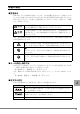
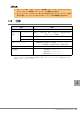
■ 製品の呼び方 本文中の製品名称を次のように略して表記します。 製品名称 本文中の表記 Microsoft® Windows Server™ 2003, Standard Edition Microsoft® Windows Server™ 2003, Enterprise Edition Microsoft® Windows Server™ 2003, Standard x64 Edition Microsoft® Windows Server™ 2003, Enterprise x64 Edition Microsoft® Windows® 2000 Server Microsoft® Windows® 2000 Advanced Server Windows Server 2003 x64 BX600 サーバブレード PRIMERGY BX660 サーバブレード BX660 サーバブレード PRIMERGY BX620 S2 サーバブレード BX620 S2 サーバ ブレード Red Hat® Enterprise Linux® AS (v.
安全上のご注意 本製品を安全にお使いいただくために、以降の記述内容を必ずお守りください。 警告 ・ 機器を勝手に改造しないでください。火災・感電の原因となります。 ・ 本体に水をかけたり、濡らしたりしないでください。火災・感電の原因となり ます。 ・ 近くで雷が発生した時は、本体の電源コードや本カードの外部接続コードを抜 いてください。そのまま使用すると、雷によっては機器を破壊し、火災の原因 となります。 注意 ・ カードは精密に作られていますので、高温・低温・多湿・直射日光など極端な 条件での使用・保管は避けてください。 またカードを曲げたり、傷つけたり、強いショックを与えないでください。 故障・火災の原因となることがあります。 ・ ご使用にならない場合は、 静電気防止のために付属のカード袋へ入れて保管し てください。 J 5
梱包物の確認 お使いになる前に、次のものが梱包されていることをお確かめください。 万一足りないものがございましたら、担当営業員または担当保守員にご連絡ください。 ・ LAN ドータカード ・ PRIMERGY BX600 サーバブレード アップデートキット ・ 保証書 ・ ユーザーズガイド(本書) Intel、および LANDesk は、米国インテル社の登録商標です。 Microsoft、Windows NT、Windows、Windows Server は、米国 Microsoft Corporation の米国およびそ の他の国における登録商標または商標です。 Linux は、Linus Torvalds 氏の米国およびその他の国における登録商標あるいは商標です。Red Hat およ び Red Hat をベースとしたすべての商標とロゴは、米国およびその他の国における Red Hat, Inc.
目次 1 LAN ドータカードについて . . . . . . . . . . . . . . . . . . . . . . . . . . . . 1.1 概要 . . . . . . . . . . . . . . . . . . . . . . . . . . . . . . . . . . . . . . . . . . . . . . . . . . . . 8 8 1.2 仕様 . . . . . . . . . . . . . . . . . . . . . . . . . . . . . . . . . . . . . . . . . . . . . . . . . . . . 9 2 LAN ドータカードの取り付け . . . . . . . . . . . . . . . . . . . . . . . . . . 10 2.1 BX600 / BX620 S2 サーバブレードへの搭載 . . . . . . . . . . . . . . . . . . 2.2 BX660 サーバブレードへの搭載 . . . . . . . . . . . . . . . . . . .
1 LAN ドータカードについて この章では、本製品の特長、仕様について説明します。 1.
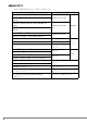
` ` 1.2 同一シャーシ内に、LAN ドータカードを搭載したサーバブレードとファイバーチャ ネルドータカードを搭載したサーバブレードの混載はできません。 ネットワークブレードスロット 3 または 4 (NET3 または 4)にスイッチブレードを搭 載する場合、ファイバーチャネルパススルーブレードの同時搭載はできません。 仕様 項目 型名 ホストバス 仕様 インタフェース PCI-X バス Rev.1.0a、PCI バス Rev. 2.
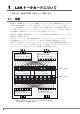
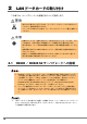
2 LAN ドータカードの取り付け この章では、サーバブレードへの搭載方法について説明します。 警告 ・ 取り付けや取り外しを行うときは、サーバブレードをシャーシから取り外して ください。感電の原因となります。 シャーシからの取り外し方法は、 『ハードウェアガイド シャーシ編』を参照して ください。 注意 ・ 内蔵オプションは、基板や半田づけした部分がむきだしになっています。これ らの部分は、人体に発生する静電気によって損傷を受ける場合があります。 取り扱う前に、サーバ本体の金属部分に触れて人体の静電気を放電してくださ い。 ・ 基板表面や半田づけの部分に触れないように、金具の部分や基板の縁を持つよ うにしてください。 ・ 拡張カードは静電気の影響を受けやすいので、伝導パッドなどの上に置くか、 取り扱う直前まで梱包袋に入れておいてください。 2.
2.1.1 LAN ドータカードの取り付け位置 BX600 / BX620 S2 サーバブレードのドータカードスロットに取り付けます。 ドータカードスロット BX600/BX620 S2サーバブレード 2.1.2 LAN ドータカードの取り付け手順 1 LAN ドータカードを取り付けるサーバブレードの電源を切ります。 → 『ハードウェアガイド シャーシ編 3.3 電源を切る』 2 シャーシの金属部分に触れて人体の静電気を放電します。 3 サーバブレードを、シャーシから取り外します。 → 『ハードウェアガイド シャーシ編 4.2 サーバブレードの取り付け/取り外し』 4 トップカバーを取り外します。 BX600 サーバブレードの場合 →『BX600 サーバブレード ユーザーズガイド 8.2 トップカバーの取り付け/取り外 し』 BX620 S2 サーバブレードの場合 →『BX620 S2 サーバブレード ユーザーズガイド 7.
5 LAN ドータカードを取り付けます。 LAN ドータカードが完全にスロットに差し込まれたことを確認してください。 LANドータカード ドータカードスロット 6 LAN ドータカードをネジで固定します。 LAN ドータカードを、カードに添付のネジ(3 本)で固定します。 ネジ 7 トップカバーを取り付けます。 BX600 サーバブレードの場合 →『BX600 サーバブレード ユーザーズガイド 8.2 トップカバーの取り付け/取り外 し』 BX620 S2 サーバブレードの場合 →『BX620 S2 サーバブレード ユーザーズガイド 7.2 トップカバーの取り付け/取 り外し』 8 サーバブレードをシャーシに取り付けます。 → 『ハードウェアガイド シャーシ編 4.
2.2 BX660 サーバブレードへの搭載 ` LAN ドータカードを外部 LAN(装置)に接続するには、シャーシのネットワークブレード スロット 3 または 4(NET3 または 4)にスイッチブレードまたは LAN パススルーブレー ドを搭載する必要があります。 2.2.1 LAN ドータカードの取り付け位置/搭載順について BX660 サーバブレードのドータカードスロットに取り付けます。 LAN ドータカードは、ドータカードスロット 1、2 の順に搭載してください。 䊄䊷䉺䉦䊷䊄䉴䊨䉾䊃㪈 䊄䊷䉺䉦䊷䊄䉴䊨䉾䊃㪉 2.2.2 LAN ドータカードの取り付け手順 ■ LAN ドータカードを 1 枚搭載する方法 1 LAN ドータカードを取り付けるサーバブレードの電源を切ります。 →『ハードウェアガイド シャーシ編 3.3 電源を切る』 2 シャーシの金属部分に触れて人体の静電気を放電します。 J 3 サーバブレードを、シャーシから取り外します。 →『ハードウェアガイド シャーシ編 4.
5 LAN ドータカードをドータカードスロット 1 に取り付けます。 LAN ドータカードが完全にスロットに差し込まれたことを確認してください。 㪣㪘㪥䊄䊷䉺䉦䊷䊄 䊄䊷䉺䉦䊷䊄䉴䊨䉾䊃㪈 ᒛ䊔䊷䉴䊗䊷䊄 6 LAN ドータカードをネジで固定します。 LAN ドータカードをカードに添付のネジ(3 本)で固定します。 7 トップカバーを取り付けます。 → 『BX660 サーバブレード ユーザーズガイド 7.2 トップカバーの取り付け/取り 外し』 8 サーバブレードをシャーシに取り付けます。 →『ハードウェアガイド シャーシ編 4.
■ LAN ドータカードを 2 枚搭載する方法 1 LAN ドータカードを取り付けるサーバブレードの電源を切ります。 →『ハードウェアガイド シャーシ編 3.3 電源を切る』 ` BX660 サーバブレードに、LAN ドータカードを 2 枚搭載している場合、サーバブ レードの電源を切っても、オンボード LAN 用の LAN リンク LED が点灯(緑) することがあります。サーバブレードが電源が切れた状態で、LAN リンク LED が点灯していても無視してください。 2 シャーシの金属部分に触れて人体の静電気を放電します。 3 サーバブレードを、シャーシから取り外します。 →『ハードウェアガイド シャーシ編 4.2 サーバブレードの取り付け/取り外し』 4 ハードディスクを取り外してから、トップカバーを取り外します。 →『BX660 サーバブレード ユーザーズガイド 7.2 トップカバーの取り付け/取り外 し』 5 拡張ベースボードを取り外します。 すでにスロット 1 に LAN ドータカードが搭載されている場合は、「■ LAN ドータ カードを 1 枚搭載する方法」(→ P.
6 ドータカードスロット 2 のドータカード固定用ネジとスペーサを取り外 します。 ` 各固定用ネジの下部にあるスペーサ(ワッシャー)は、ドータカードス ロット 2 にドータカードを取り付ける場合には不要です。なお、ドータ カードを取り外す場合には、同スペーサの再取り付けが必要になりますの で、大切に保管してください。 ࿕ቯ↪䊈䉳 䉴䊕䊷䉰 䋨䊪䉾䉲䊞䍎䋩 ࿕ቯ↪䊈䉳 7 LAN ドータカードをドータカードスロット 2 に取り付けます。 㪣㪘㪥䊄䊷䉺䉦䊷䊄 䊄䊷䉺䉦䊷䊄䉴䊨䉾䊃㪉 16
8 ドータカードスロット 2 に取り付けた LAN ドータカードを、手順 6 で取 り外したネジで固定します。 スペーサの再取り付けは、必要ありません。 9 手順 5 で取り外した拡張ベースボードを取り付けます。 10 LAN ドータカードをドータカードスロット 1 に取り付けます。 「■ LAN ドータカードを 1 枚搭載する方法」(→ P.13)の手順 5 ~ 6 を参照して取 り付けてください。 11 トップカバーを取り付けます。 →『BX660 サーバブレード ユーザーズガイド 7.2 トップカバーの取り付け/取り外 し』 12 サーバブレードを、シャーシに取り付けます。 →『ハードウェアガイド シャーシ編 4.
3 LAN ドライバのインストール この章では、LAN ドライバのインストール方法について説明します。 3.1 モジュールのバージョンレベル 本製品は、次の LAN ドライバで動作します。 OS の種類 LAN ドライバのバージョン Windows Server 2003 Windows 2000 Server 『PG-185x/186x/187x/188x/189x/PG-LND101 LAN ドライ バ V9.1』 Windows Server 2003 x64 『PG-185x/186x/187x/188x/189x/PG-LND101 LAN Driver & Intel(R) PROSet LAN ドライバ V9.2』以降 ` ` LAN ドライバは、次のいずれかから入手してインストールしてください。 ・サーバブレード添付の ServerStart CD-ROM 内の LAN ドライバ ・富士通パソコン情報サイト FMWORLD.NET の PRIMERGY 向けホームページ (http://www.fmworld.
3.1.1 バージョンレベルの確認方法 バージョンレベルの確認方法は次のとおりです。 OS の種類 確認方法 Windows Server 2003 ・ Intel® PROSet の「ネットワークドライバ」のドライバ情 報の e1000325.sys のバージョン ・「デバイスマネージャ」で表示される LAN アダプタの名 称を右クリック後、「プロパティ」→「ドライバ」→「ド ライバの詳細」で表示される e1000325.sys のバージョン Windows Server 2003 x64 ・ Intel® PROSet の「ネットワークドライバ」のドライバ情 報の e1G5132e.sys のバージョン ・「デバイスマネージャ」で表示される LAN アダプタの名 称を右クリック後、「プロパティ」→「ドライバ」→「ド ライバの詳細」で表示される e1G5132e.sys のバージョン Windows 2000 Server ・ Intel® PROSet の「ネットワークドライバ」のドライバ情 報の e1000nt5.
3 [デバイスマネージャ]をクリックします。 デバイスマネージャの一覧で、認識されているネットワークアダプタが存在するか を確認します。 ⼂䈘䉏䈩䈇䈭䈇 䊈䉾䊃䊪䊷䉪䉝䉻䊒䉺 ⼂䈘䉏䈩䈇䉎 䊈䉾䊃䊪䊷䉪䉝䉻䊒䉺 認識されているネットワークアダプタが存在する場合は、「ネットワークアダプタ」 が表示されます。 ・ 認識されているネットワークアダプタが存在する場合 最初に「ネットワークアダプタ」配下の LAN デバイス名に対して「3.2.2 LAN ド ライバの更新」(→ P.21)を行ったあと、「その他のデバイス」配下の「イーサ ネットコントローラ」に対して「3.2.3 LAN ドライバのインストール」(→ P.
ドライバのインストールが開始されたあと、次の画面が表示されます。 ` 3.2.2 [完了]をクリックすると、 「ヘルプとサポートセンター」の画面が表示されま すが、[×]を クリックして画面を閉じてください。インストール後、デバイ スマネージャの LAN デバイス名に「!」マークが表示されますが、すべての LAN ドライバインストール後、再起動すると正常に表示されます。 認識されているネットワークアダプタが存在しない場合 「その他のデバイス」配下の「イーサネットコントローラ」に対して、 「3.2.3 LAN ドライバのインストール」(→ P.
3 LAN デバイスのアイコンをダブルクリックします。 プロパティが表示されます。 4 [ドライバ]タブをクリックし、[ドライバの更新]をクリックします。 「ハードウェアの更新ウィザード」画面が表示されます。 5 「ソフトウェアを自動的にインストールする」を選択し、[次へ]をクリッ クします。 ドライバのインストールが開始されます。 6 [完了]をクリックします。 7 [閉じる]をクリックします。 ■ Windows Server 2003 x64 の場合 1 「ネットワークアダプタ」配下の LAN デバイス名をダブルクリックしま す。 ` LAN デバイス名は、次のように表示されます。 LAN カード PG-LND101 ` LAN デバイス名 Intel(R) PRO/1000 MB Dual Port Server Connection AFT などが作成済みの場合、次の仮想アダプタが存在しますが、選択しな いでください。 ・Intel(R) Advanced Network Service Virtual Adapter 2 LAN ドライバの CD またはフロッピーディスクをセッ
8 「製造元のファイルのコピー元」を LAN ドライバの格納されている場所 に指定し、[OK]をク リックします。 9 「Intel(R) PRO/1000 MB Dual Port Server Connection」が表示された ら、[次へ]をクリックします。 ドライバのインストールが開始されます。 10 [完了]をクリックします。 11 [閉じる]をクリックします。 ドライバの更新を行ったすべての LAN アダプタに対して正しく更新されていることを、 「3.1 モジュールのバージョンレベル」(→ P.18)を参照して、バージョンが正しいことを 確認してください。 ` 3.2.
■ Windows Server 2003 x64 の場合 1 LAN ドライバの CD またはフロッピーディスクをセットします。 ダウンロードした LAN ドライバの格納したフォルダを確認しておいてください。 2 「その他のデバイス」配下の「イーサネットコントローラ」をダブルク リックします。 「イーサネットコントローラのプロパティ」画面が表示されます。 3 [ドライバ]タブをクリックし、[ドライバの更新]をクリックします。 「ハードウェアの更新ウィザードの開始」画面が表示されます。 4 「一覧または特定の場所からインストールする」を選択し、[次へ]をク リックします。 5 「検索しないで、インストールするドライバを選択する」を選択し、[次 へ]をクリックします。 6 [ディスク使用]をクリックします。 7 「製造元のファイルのコピー元」を LAN ドライバの格納されている場所 に指定し、[OK]をク リックします。 8 「Intel(R) PRO/1000 MB Dual Port Server Connection」が表示された ら、[次へ]をクリックします。 ドライバのインストールが開始さ
4 [次へ]をクリックします。 5 「デバイスに最適なドライバをインストールする(推奨)」を選択し、[次 へ]をクリックします。 ドライバファイルの特定画面が表示されます。 6 検索場所のオプションに「CD-ROM ドライブ」または「フロッピーディ スクドライブ」などを選択し、[次へ]をクリックします。 検出されたドライバが表示されます。 7 [次へ]をクリックします。 ドライバのインストールが開始され、終了すると完了画面が表示されます。 8 [完了]をクリックします。 9 [閉じる]をクリックします。 10 LAN ドライバの CD またはフロッピーディスクを取り出し、サーバブ レードを再起動します。 ドライバのインストールを行ったすべての LAN アダプタに対して、正しく更新されてい ることを、「3.1 モジュールのバージョンレベル」(→ P.18)を参照して、バージョンが正 しいか確認して ください。 ` LAN デバイス名は、次のように表示されます。 LAN カード PG-LND101 ` 3.2.
4 「Intel(R) PRO Network Connections Drivers」を選択し、「変更と削 除」をクリックします。 5 画面の指示に従い、削除します。 6 システムを再起動します。 26
Intel® PROSet 4 この章では、Intel® PROSet について説明します。 ` ` 4.1 Intel® PROSet は、次のいずれかから入手してインストールしてください。 ・サーバブレード添付の ServerStart CD-ROM 内の Intel® PROSet ・富士通パソコン情報サイト FMWORLD.NET の PRIMERGY 向けホームページ (http://www.fmworld.net/biz/primergy/)に公開されている Intel® PROSet ・Windows Server 2003 / Windows 2000 Server の場合 PG-185x/186x/187x/188x/189x/PG-LND101 LAN ドライバ V9.1』の Intel® PROSet ・Windows Server 2003 x64 の場合 『PG-185x/186x/187x/188x/189x/PG-LND101 LAN Driver & Intel(R) PROSet LAN ドライバ V9.
4.2 Windows Server 2003 / Windows 2000 Server システムでの注意事項 ・ ServerStart を利用してドライバを自動インストールした場合は、Intel® PROSet も自動的 にインストールされます 。 ・ Intel® PROSet が「コントロールパネル」に表示されていれば、インストール済みです。 本製品は、次の Intel® PROSet でサポートされます。 - Windows Server 2003 / Windows 2000 Server の場合 「V9.1(V9.1.0.0)」の Intel® PROSet - Windows Server 2003 x64 の場合 「V9.
` チームおよび VLAN がある場合は、アンインストールする前に Intel® PROSet でチームおよび VLAN をすべて削除してください。 →「5.3 チームの削除」(P.34) →「6.3 VLAN の削除」 (P.39) 3 「プログラムの追加と削除」または「アプリケーションの追加と削除」 を クリックします。 4 「Intel(R) PROSet for wired Connections」を選択し、「削除」をク リックします。 5 画面の指示に従って、アンインストールします。 4.5 LAN ドータカードのテスト LAN ドータカードのテストは、次の手順で行います。 4.5.
5 チーム化(AFT/ALB/SFT) この章では、チーム化(AFT/ALB/SFT)について説明します。 ド ` 5.
・ SFT の構成例 PRIMERGY スイッチ1 LAN LAN Primary link Secondary link *)LAN カードとスイッチ間のリンク断と同様の異常しか検出できません。したがって、 スイッチが部分的に故障しただけで、カードが接続されているポートがリンクレベルで 正常な場合は、通常、経路の切り替えは発生しません。 ■ 注意事項 チーム化を使用する場合の注意事項を次に示します。 詳細については、Intel® PROSet の「Help」を参照してください。 ・ チーム化は、Windows(SP2 以降必須)でのみ使用できます。 ・ チームを構成すると、OS 上に仮想アダプタ(例:Intel(R) Advanced Network Services Virtual Adapter など)が作成されます。上位プロトコルは、チームを構成している個々 の物理アダプタではなく、この仮想アダプタにバインドされます。 ・ 高速チーム機能は使用しないでください。 ・ ALB 使用時は、Windows Load Balancing Service(WLBS)や NLB(Network Load B
■ LAN ドータカード使用時のチーミングについて 本製品でチーミングを行う場合、使用する OS によって、使用するソフトウェアとチーミ ング可能な組合せが異なります。次の表に従ってご使用ください。 ・ BX600 / BX660 サーバブレードの場合 動作 OS Windows Linux v.
5.
5.
5.
5.
6 VLAN この章では、VLAN について説明します。 6.1 VLAN について 仮想 LAN(VLAN)とは、LAN に接続される装置を、物理的な接続形態ではなく論理的に グループ化したものです。VLAN は、装置が使用できるネットワークセグメントを特定す ることができます。これにより、ネットワークの性能とセキュリィティの向上が図られま す。 また、VLAN は、複数のユーザや装置を論理的にグル-プ化する機能があるため、建物間 のネットワーク管理を容易にすることができます。 通常 VLAN とは、スイッチ側の設定によるもので、装置は、1 つの LAN カードごとに 1 つの VLAN にしか属することができません。しかし、本ドライバでは 1 つの LAN カード 上に複数の VLAN を構成することが可能です。また、本ドライバは、IEEE802.1Q で定義 された VLAN をサポートしています。 PRIMERGY スイッチ (IEEE802.
・ VLAN 上では IP 以外のプロトコルを使用しないでください。 富士通通信制御サービスで、LLC、LNDFC プロトコルをインストールすると、VLAN とこれらのプロトコルは、無条件にバインド(接続)されてしまいます。したがって、 IP 以外のプロトコルが、VLAN と同時にインストールされたシステムでは、VLAN とそ れらのプロトコルのバインドを解除してください。 ・ 1 つの LAN ポートに設定可能な VLAN の個数は最大 10 個です。 ・ Windows で NetBIOS over TCP/IP が有効な VLAN は、システム全体で最大 4 本にしてく ださい。 6.
6.
付録 A A.1 ローカルアドレスの設定 ローカルアドレスを設定する場合は、次の手順で行います。 1 管理者権限でログオンします。 2 「スタート」ボタン→「設定」→「コントロールパネル」→「有線用イン テル ® PROSet」の順にクリックし、Intel® PROSet を起動します。 3 設定する LAN アダプタを選択し、[詳細設定]タブをクリックします。 4 「ローカル管理されるアドレス」の値に設定するローカルアドレスを設定 します。 「02」で始まる 16 進数 12 桁を入力してください。 5 [OK]をクリックし、Intel® PROSet を終了します。 6 ` システムを再起動します。 グローバルアドレスに戻したい場合は、手順 4 で設定した値を削除してください。 A.
A.
Before Reading This Manual Thank you for purchasing the PRIMERGY 1Gbit/s Ethernet I/O Module (hereinafter referred to as this product or the card). The card can be installed in the daughter card slot of the Fujitsu server blade to configure the Local Area Network (LAN) system. This manual explains the 1Gbit/s Ethernet I/O Modules and the LAN driver (for Windows). Read this manual carefully to handle the product correctly.
Remarks Warning Descriptions Various symbols are used throughout this manual. These are provided to emphasize important points for your safety and that of others. The symbols and their meanings are as follows. Be sure to fully understand these before reading this manual. WARNING Ignoring this symbol could be potentially lethal. CAUTION Ignoring this symbol may lead to injury and/or damage the device or hardware options.
Abbreviations The following expressions and abbreviations are used throughout this manual. Product names Microsoft® Windows Server™ 2003, Standard Edition Microsoft® Windows Server™ 2003, Enterprise Edition Microsoft® Windows Server™ 2003, Standard x64 Edition Microsoft® Windows Server™ 2003, Enterprise x64 Edition Microsoft® Windows® 2000 Server Microsoft® Windows® 2000 Advanced Server Red Hat® Enterprise Linux® ES (v.3 for x86) Red Hat® Enterprise Linux® AS (v.3 for x86) Red Hat® Enterprise Linux® ES (v.
Safety For your safety and that of others, follow the guidelines provided on the following pages concerning the use of this product. WARNING • Do not tinker with the product. Doing so may cause fire or electric shock. • Keep the product away from water. Failure to do so may cause fire or electric shock. • When there is lightning nearby, unplug all power cords and external connecting cords from the product. Failure to do so may cause destruction of the devices and fire.
Contents 1 1Gbit/s Ethernet I/O Module . . . . . . . . . . . . . . . . . . . . . . . . . . 1.1 Overview . . . . . . . . . . . . . . . . . . . . . . . . . . . . . . . . . . . . . . . . . . . . . . 1.2 Specifications . . . . . . . . . . . . . . . . . . . . . . . . . . . . . . . . . . . . . . . . . . . 2 Installing a 1Gbit/s Ethernet I/O Module . . . . . . . . . . . . . . . . 2.1 Installing to BX620 S2 Server Blade . . . . . . . . . . . . . . . . . . . . . . . . . 3 Installing the LAN Driver . . . . . .
1 1Gbit/s Ethernet I/O Module This chapter explains the features and specifications of this product. 1.1 Overview This product is an expansion LAN card exclusive to BX620 S2 Server Blade. This product has a dual-port (2 ports) LAN controller, and provides LAN connection completely separate/ independent of the onboard LAN. The external access is performed via the Switch Blade installed to the network blade slot 3 or 4 (NET3 or NET4) on the chassis. One product can be added to one BX620 S2 Server Blade.
` ` 1.2 A server blade installed with a 1Gbit/s Ethernet I/O Module and a server blade installed with a 2Gbit/s FC I/O Module cannot be installed to the same chassis. When a Switch Blade or a GbE Pass-Thru Blade is installed to network blade slot 3 or 4 (NET3 or 4), a FC Pass-Thru Blade cannot be installed at the same time. Specifications Specifications PG-LND101 Interface PCI-X bus Rev.1.0a, PCI bus Rev.2.3 (Compatible with logical specifications) 64 bit/133MHz Data transfer rate Max. 1GB/sec.
2 Installing a 1Gbit/s Ethernet I/O Module This chapter explains how to install a 1Gbit/s Ethernet I/O Module to the server blade. WARNING • When installing or removing the 1Gbit/s Ethernet I/O Module, make sure to remove the server blade from the chassis. Failure to do so may cause electric shock. For details on how to remove the server blade from the chassis, refer to "Hardware Guide (Chassis)". CAUTION • The circuit boards and soldered parts of internal options are exposed.
2.1 Installing to BX620 S2 Server Blade ` To connect a 1Gbit/s Ethernet I/O Module to the external LAN (device), it is necessary to install a Switch Blade or GbE Pass-Thru Blade to network blade slot 3 or 4 (NET3 or 4) of the chassis. 2.1.1 Location of 1Gbit/s Ethernet I/O Module Installation Install the 1Gbit/s Ethernet I/O Module in the daughter card slot in the BX620 S2 Server Blade. Daughter card slot BX620 S2 Server Blade 2.1.
5 Install the 1Gbit/s Ethernet I/O Module. Check that the 1Gbit/s Ethernet I/O Module is securely inserted to the slot. 1Gbit/s Ethernet I/O Module Daughter card slot 6 Secure the 1Gbit/s Ethernet I/O Module with the screws. Fix the 1Gbit/s Ethernet I/O Module using the three screws supplied with the card. Screws 7 Attach the top cover. →"8.2 Removing and Attaching the Top Cover" in "BX620 S2 Server Blade User's Guide" 8 Install the server blade to the chassis. →"4.
3 Installing the LAN Driver This chapter explains how to install the LAN driver. 3.1 Module Version Level This product runs on the following LAN driver. OS type LAN driver version Windows Server 2003 Windows 2000 Server "PG-185x/186x/187x/188x/189x/PG-LND101 LAN driver V9.1" Windows Server 2003 x64 "PG-185x/186x/187x/188x/189x/PG-LND101 LAN Driver & Intel(R) PROSet LAN driver V9.
3.1.1 How to check version level How to confirm the version level is described below. OS types Windows Server 2003 Confirmation method • Intel(R) PROSet [Network Driver] driver information e1000325.sys version • Right-click the LAN adapter name displayed in [Device Manager], and [Properties] → [Driver] → [Driver Details] displays e1000325.sys version Windows Server 2003 x64 • Intel(R) PROSet [Network Driver] driver information e1G5132e.
3 Click [Device Manager]. On the Device Manager list, check if a recognized network adapter is present. Recognized network adapters Unrecognized network adapters When a recognized network adapter is present, [Network adapters] appears. • When a recognized network adapter is present Perform "3.2.2 Updating LAN Drivers" (Jpg.56) on the LAN device name under [Network adapters], then "3.2.3 Installing the LAN Driver" (Jpg.58) on [Ethernet controller] under [Other devices].
Perform "3.2.3 Installing the LAN Driver" (Jpg.58) on [Ethernet controller] under [Other devices]. 3.2.2 Updating LAN Drivers Perform the following procedures on all LAN device names under [Network adapters] in [Device Manager]. Windows Server 2003/Windows 2000 Server 1 Double-click a LAN device name under [Network adapters]. ` The LAN device names are displayed as follows.
` When AFT is already created, the virtual adapter below exists. Do not select it. • Intel(R) Advanced Network Service Virtual Adapter 2 Insert the LAN driver CD or floppy disk. Confirm the folder that contains the downloaded LAN driver in advance. 3 Double-click the LAN device icon. The properties are displayed. 4 Click the [Driver] tab and click [Update Driver]. The [Welcome to the Upgrade Device Driver Wizard] window appears. 5 Select [Install from a list or specific location] and click [Next].
3.2.3 Installing the LAN Driver According to the procedures below, install the LAN driver for all the Ethernet controllers listed under Other Devices of Device Manager. Windows Server 2003 1 Insert a CD or floppy disk of the LAN driver. Confirm the folder that contains the downloaded LAN driver in advance. 2 Double-click [Ethernet controller] under [Other devices]. The [Ethernet Controller Properties] window appears. 3 Click the [General] tab and click [Reinstall Driver].
8 When [Intel(R) PRO/1000MB Dual Port Server Connection] appears, click [Next]. The driver will be installed. 9 Click [Finish]. 10 Click [Close] to exit the properties window. Properties window closes. 11 Eject the ServerStart CD-ROM, and restart the server blade.
Windows 2000 Server 1 Insert a CD or floppy disk of the LAN driver. Confirm the folder that contains the downloaded LAN driver in advance. 2 Double-click [Ethernet controller] under [Other devices]. The [Ethernet Controller Properties] window appears. 3 Click the [General] tab and click [Reinstall Driver]. The [Device Driver Upgrade Wizard] window appears. 4 Click [Next]. 5 Select [Search for a suitable driver for my device (recommended)] and click [Next]. The [Identify Driver File] window appears.
3.2.4 Removing the Driver Perform the following procedures to remove the driver. 1 Log on with administrator privileges. 2 Remove Intel® PROSet. J"4.4 Uninstalling"(pg.64) 3 Click [Start] → [Settings] → [Control Panel] → [Add or Remove Applications] or [Add or Remove Programs]. 4 Select [Intel(R) PRO Network Connections Drivers] and click [Change/Remove]. 5 Follow the instruction on the window to remove the driver. 6 Restart the system.
Intel® PROSet 4 This chapter explains Intel® PROSet. ` ` 4.1 Obtain and install Intel® PROSet from and of the following: • Intel(R)PROSet in the ServerStart CD-ROM provided with the server blade • Intel(R)PROSet available on the Fujitsu PRIMERGY website (http:// primergy.fujitsu.com) • For Windows Server 2003/ Windows 2000 Server Intel(R)PROSet "PG-185x/186x/187x/188x/189x/PG-LND101 LAN driver V9.
4.2 Notes on Windows Server 2003/ Windows 2000 Server System • When a driver is automatically installed using ServerStart, Intel® PROSet is also installed automatically. • If Intel® PROSet is displayed in the [Control Panel], it is already installed. This product is supported in the following Intel® PROSet: - For Windows Server 2003/ Windows 2000 Server Intel® PROSet "V9.1 (V9.1.0.0)" - For Windows Server 2003 x64 Intel® PROSet "V9.
4.4 Uninstalling Perform the following procedures to uninstall Intel® PROSet. 1 Log on with the administrator privileges. 2 Click [Start] → [Settings] → [Control Panel]. ` If team and VLAN are included, remove both of them using Intel® PROSet before uninstallation. J"5.3 Removing a Team"(pg.69) J"6.3 Removing VLAN"(pg.74) 3 Click [Add or Remove Programs] or [Add/Remove Applications]. 4 Select [Intel(R) PROSet for wired Connections] and click [Remove].
5 Teaming(AFT/ALB/SFT) This chapter explains Teaming (AFT/ALB/SFT). ` 5.1 In a system configuration containing a Switch Blade in the BX600 Server Blade, the Adaptive Load Balancing (ALB) function is not available. Teaming(AFT/ALB/SFT) AFT/ALB Adapter Fault Tolerance (AFT) is a technology of redundant paths between the server and switch (hub) using multiple Ethernet controllers (LAN adapters).
SFT Switch Fault Tolerance (SFT) is a redundant function with a configuration in which each LAN card is connected to a different switch. Spanning tree function on the switch is enabled, so that the switch can be used in the redundant configuration. When an error occurs (*) between the LAN card and its connected switch, the path to use is switched. However, errors between switches (arrows in the following figure) cannot be detected.
Teaming 1Gbit/s Ethernet I/O Module during use When teaming this product, the possible software and teaming combinations will vary depending on the OS being used. Adhere to the table below. OS Windows Linux v.
5.2 Creating a Team Perform the following procedures to create a team. 1 Log on with the administrator privileges. 2 Click [Start] → [Settings] → [Control Panel] → [Intel®PROSet Wired], and start Intel® PROSet. 3 Select a LAN adapter to build in the team, and right click. 4 Click [Add to Team] → [Create New Team...]. The [Teaming wizard] window appears. 5 Select a Teaming type with which you want to create a Team.
5.3 Removing a Team Perform the following procedures to remove a team. 1 Log on with the administrator privileges. 2 Click [Start] → [Settings] → [Control Panel] → [Intel®PROSet Wired], and start Intel® PROSet. 3 Select the team to delete. 4 Click [Remove team]. A confirmation message appears. 5 Click [OK]. 6 Click [OK] and exit Intel® PROSet. 7 Restart the system.
5.4 Event Log When AFT, ALB, or SFT is used, the following event logs will be generated (source: i ANSMiniport). ID Type Message 6 Information Primary adapter is initialized: (adapter name) 7 Information Adapter is initialized: (adapter name) 8 Information (team name): Team is initialized.
5.5 Detecting an Error in 1Gbit/s Ethernet I/O Modules Composing a Team and Replacing a Defective Card Follow the steps below to replace a 1Gbit/s Ethernet I/O Module composing a team. 1 Replace a 1Gbit/s Ethernet I/O Module in the server blade. 2 Start the server blade. 3 Log on with administrator privileges. 4 Exit all running applications. 5 Click [Start] → [Settings] → [Control Panel] → [Intel®PROSet Wired], and start Intel® PROSet. 6 Select the newly installed LAN adapter, and right click.
6 VLAN This chapter explains VLAN. 6.1 VLAN Virtual LAN (VLAN) is not a physical connection but a logical group of LAN-connected devices. VLAN can specify network segments that the device can use. This enhances network performance and security. VLAN also has a function to logically group multiple users and devices, enabling network management among buildings easily. Normally, VLAN is set on the switch so that a device can only belong to a single VLAN per Ethernet controller.
6.2 Creating VLAN Perform the following procedures to create a VLAN. 1 Log on with administrator privileges. 2 Set the port of the switch connected to the Ethernet controller to enable send/receive of VLAN tag frames. 3 Click [Start] → [Settings] → [Control Panel] → [Intel®PROSet Wired], and start Intel® PROSet. 4 Select LAN adapter to set VLAN, and right click. A VLAN cannot be set to an adapter composing a team. 5 Click [Add VLAN]. 6 Set [ID] and [Name], then click [OK].
6.3 Removing VLAN Follow the steps below to delete a VLAN. 1 Log on with administrator privileges. 2 Click [Start] → [Settings] → [Control Panel] → [Intel®PROSet Wired], and start Intel® PROSet. 3 Select the VLAN to delete and click it. 4 Click [Remove VLAN]. A confirmation message appears. 5 Click [OK]. When an attempt is made to delete the last VLAN, the message will be displayed. Click [OK]. 6 Click [OK] and exit Intel® PROSet. 7 Restart the system.
Appendix A A.1 Setting Local Address Perform the following procedures to set a local address. 1 Log on with administrator privileges. 2 Click [Start] → [Settings] → [Control Panel] → [Intel®PROSet Wired], and start Intel® PROSet. 3 Select a LAN adapter to set the local address and click the [Advanced] tab. 4 Specify a local address to set the value in [Locally Administered Address]. Enter hexadecimal 12-digit number starting with "02". 5 Click [OK] and exit Intel® PROSet. 6 ` Restart the system.
A.3 Other Notes • The PXE boot (network boot) function is not supported for the LAN port of the 1Gbit/s Ethernet I/ O Module. Execute PXE boot to the onboard LAN controller. • WakeOnLAN function of the 1Gbit/s Ethernet I/O Module is not supported. • The MAC and IP addresses of the 1Gbit/s Ethernet I/O Module cannot be confirmed in the management blade. Confirm this information in Intel(R) PROSet or the hardware management program on the OS.
Appendix B Contact Information • Australia: Fujitsu Australia Limited Tel: +61-2-9776-4555 Fax: +61-2-9776-4556 Address: 2 Julius Avenue (Cnr Delhi Road) North Ryde, Australia N.S.W. 2113 • China: Fujitsu (China) Holdings Co., Ltd. Tel: +86-21-5292-9889 Fax: +86-21-5292-9566 Address: 18F, Citic Square, 1168 West Nanjing Road Shanghai, China 200041 • Hong Kong: Fujitsu Hong Kong Limited Tel: +852-2827-5780 Fax: +852-2827-4724 Address: 10/F.
• Singapore: Fujitsu Asia Pte. Ltd. Tel: +65-6777-6577 Fax: +65-6771-5502 Address: 20, Science Park Road, #03-01 TeleTech Park, Singapore Science Park II, Singapore 117674 • Taiwan: Fujitsu Taiwan Limited Tel: +886-2-2311-2255 Fax: +886-2-2311-2277 Address: 19F, No.39, Section 1, Chung hwa Road Taipei, Taiwan • Thailand: Fujitsu Systems Business (Thailand) Ltd.
PRIMERGY LAN ドータカード(PG-LND101) 取扱説明書 1Gbit/s Ethernet I/O Module(PG-LND101) User’s Guide B7FY-1651-01-00 発行日 発行責任 2005 年 11 月 富士通株式会社 Issued on Issued by November, 2005 FUJITSU LIMITED Printed in Japan ● 本書の内容は、改善のため事前連絡なしに変更することがあります。 ● 本書に記載されたデータの使用に起因する、第三者の特許権およびその他の 権利の侵害については、当社はその責を負いません。 ● 無断転載を禁じます。 ● 落丁、乱丁本は、お取り替えいたします。 • The contents of this manual may be revised without prior notice.
こ のマ ニ ュ アルは リ サイ ク ルに配慮 し て製本 さ れています。 不要にな っ た際は、 回収 ・ リ サイ ク ルに出 し て く だ さ い。