C122-H004-07EN PRIMEQUEST 1000 Series Hardware Installation Manual FUJITSU LIMITED
PRIMEQUEST 1000 Series Hardware Installation Manual Preface Preface This manual describes the specifications and installation location requirements of PRIMEQUEST 1000 series installation. The manual is intended for system administrators. For details on the regulatory compliance statements and safety precautions, see the PRIMEQUEST 1000 Series Safety and Regulatory Information (C122-E115XA).
PRIMEQUEST 1000 Series Hardware Installation Manual Preface - Trademarks Organization of this manual This manual is organized as follows. CHAPTER 1 Installation Information Chapter 1 provides various useful information on PRIMEQUEST 1000 series installation. The information includes device configuration details, device outline drawings, installation specifications, and various layout diagrams.
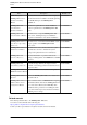
PRIMEQUEST 1000 Series Hardware Installation Manual Preface Title Description Manual code SPARC Enterprise/ PRIMEQUEST Common Installation Planning Manual Provides the necessary information and concepts you C120-H007EN should understand for installation and facility planning for SPARC Enterprise and PRIMEQUEST installations. PRIMEQUEST 1000 Series Hardware Installation Manual Includes the specifications of and the installation location requirements for the PRIMEQUEST 1000 series.
PRIMEQUEST 1000 Series Hardware Installation Manual Preface Title Description Manual code ServerView Suite Describes how to install and start ServerView None ServerView Operations Operations Manager in a Windows environment. Manager Quick Installation (Windows) ServerView Suite Describes how to install and start ServerView ServerView Operations Operations Manager in a Linux environment.
PRIMEQUEST 1000 Series Hardware Installation Manual Preface Title Description Manual code The Fujitsu Technology Solutions manuals server http://manuals.ts.fujitsu.com/index.php?id=0 MegaRAID SAS Device Driver Installation Provides technical information on using array None controllers. Refer to the manual from the SVS-DVD2 supplied with the product or from the following URL: The Fujitsu Technology Solutions manuals server http://manuals.ts.fujitsu.com/index.
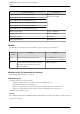
PRIMEQUEST 1000 Series Hardware Installation Manual Preface Formal product name Abbreviation Microsoft® Windows Server® 2008 Standard Windows Windows Server 2008 Microsoft® Windows Server® 2008 Enterprise Microsoft® Windows Server® 2008 Datacenter Microsoft® Windows Server® 2008 R2 Standard Microsoft® Windows Server® 2008 R2 Enterprise Microsoft® Windows Server® 2008 R2 Datacenter VMware vSphere(R) 4 vSphere 4, VMware 4 VMware vSphere(R) 5 vSphere 5, VMware 5 VMware(R) ESX(R) 4 ESX, ESX 4.
PRIMEQUEST 1000 Series Hardware Installation Manual Preface Notes on notations - In this manual, the Management Board and MMB firmware are abbreviated as "MMB." - In this manual, IOBs and GSPBs (LIOBs and LGSPBs within partitions) are collectively referred to as IO Units. - Screenshots contained in this manual may differ from the actual product screen displays.
PRIMEQUEST 1000 Series Hardware Installation Manual Preface - The PDF file of this manual is intended for display using Adobe® Reader® in single page viewing mode at 100% zoom. - The PRIMEQUEST 1800E2/1800E model supports only 200 V power supply. Trademarks - Microsoft, Windows, and Windows Server are trademarks or registered trademarks of Microsoft Corporation in the United States and/or other countries.
PRIMEQUEST 1000 Series Hardware Installation Manual Preface * The label is affixed at either location.
PRIMEQUEST 1000 Series Hardware Installation Manual Preface Warning label location (PCI_Box) Notes on Handling the Product Adding optional products For stable operation of the PRIMEQUEST 1000 series server, use only a Fujitsu certified optional product as an added option. Note that the PRIMEQUEST 1000 series server is not guaranteed to operate with any optional product not certified by Fujitsu.
PRIMEQUEST 1000 Series Hardware Installation Manual Preface - Unpacking an optional Fujitsu product, such as an optional adapter, delivered to the customer Modifying or recycling the product Modifying this product or recycling a secondhand product by overhauling it without prior approval may result in personal injury to users and/or bystanders or damage to the product and/or other property.
PRIMEQUEST 1000 Series Hardware Installation Manual Preface https://www-s.fujitsu.com/global/contact/computing/PRMQST_feedback.html Warranty If a component failure occurs during the warranty period, we will repair it free of charge in accordance with the terms of the warranty agreement. For details, see the warranty. Before requesting a repair If a problem occurs with the product, confirm the problem by referring to 11.2 Troubleshooting in the PRIMEQUEST 1000 Series Administration Manual (C122-E108EN).
PRIMEQUEST 1000 Series Hardware Installation Manual Contents Contents CHAPTER 1 Installation Information .................................................................................................................. 1 1.1 Device Configuration Details .................................................................................................................... 2 1.2 Outline Drawings of the Devices .....................................................................................................
PRIMEQUEST 1000 Series Hardware Installation Manual Contents B.4 Cable Connector .................................................................................................................................... 86 Index .................................................................................................................................................................
PRIMEQUEST 1000 Series Hardware Installation Manual Figures Figures Warning label location (PRIMEQUEST 1800E2/1800E rear) ............................................................................. ix Warning label location (PRIMEQUEST 1800E2/1800E rear) (IOBs removed) .................................................. ix Warning label location (PCI_Box) ....................................................................................................................... x FIGURE 1.
PRIMEQUEST 1000 Series Hardware Installation Manual Figures FIGURE A.17 Outline drawing of the 19-inch rack Model 1624 (base/without stabilizer) ................................ 73 FIGURE A.18 Outline drawing of the 19-inch rack Model 1624 (expansion/with stabilizer) ............................ 74 FIGURE A.19 Outline drawing of the 19-inch rack Model 1624 (expansion/without stabilizer) ....................... 75 FIGURE A.20 Bottom view drawing of the (standard) 19-inch rack ...............................
PRIMEQUEST 1000 Series Hardware Installation Manual Tables Tables TABLE 1.1 Device names and configuration details .......................................................................................... 2 TABLE 1.2 PRIMEQUEST 1800E2 installation specifications ........................................................................... 6 TABLE 1.3 PRIMEQUEST 1800E installation specifications ............................................................................. 7 TABLE 1.
PRIMEQUEST 1000 Series Hardware Installation Manual Tables xviii C122-H004-07EN
CHAPTER 1 Installation Information This chapter provides various useful information on PRIMEQUEST 1000 series installation. The information includes device configuration details, device outline drawings, installation specifications, and various layout diagrams. 1.1 Device Configuration Details ........................................ 2 1.2 Outline Drawings of the Devices .................................. 3 1.3 Installation Specifications ............................................. 6 1.
PRIMEQUEST 1000 Series Hardware Installation Manual CHAPTER 1 Installation Information 1.1 Device Configuration Details TABLE 1.1 Device names and configuration details lists device names and configuration details. TABLE 1.1 Device names and configuration details Device name Description of configuration Size (height) PRIMEQUEST 1800E2/1800E Can accommodate up to 4 system boards (up to 8 CPUs) and up to 2 IO boards. 12U PCI_Box Expands the number of PCI Express slots.
PRIMEQUEST 1000 Series Hardware Installation Manual CHAPTER 1 Installation Information 1.2 Outline Drawings of the Devices This section provides outline drawings of each device. - 1.2.1 PRIMEQUEST 1800E2/1800E outline drawings - 1.2.2 PCI_Box outline drawings 1.2.1 PRIMEQUEST 1800E2/1800E outline drawings This section includes outline drawings of the PRIMEQUEST 1800E2/1800E (front, rear, top, and right side views). PRIMEQUEST 1800E2/1800E (front view) FIGURE 1.
PRIMEQUEST 1000 Series Hardware Installation Manual CHAPTER 1 Installation Information PRIMEQUEST 1800E2/1800E (top view) FIGURE 1.3 PRIMEQUEST 1800E2/1800E (top view) PRIMEQUEST 1800E2/1800E (right side view) FIGURE 1.4 PRIMEQUEST 1800E2/1800E (right side view) 1.2.2 PCI_Box outline drawings This section includes outline drawings of the PCI_Box (front, rear, top, and right side views).
PRIMEQUEST 1000 Series Hardware Installation Manual CHAPTER 1 Installation Information FIGURE 1.5 PCI_Box front view PCI_Box rear view FIGURE 1.6 PCI_Box rear view PCI_Box top view FIGURE 1.7 PCI_Box top view PCI_Box right side view FIGURE 1.
PRIMEQUEST 1000 Series Hardware Installation Manual CHAPTER 1 Installation Information 1.3 Installation Specifications This section lists the installation specifications of each device. - 1.3.1 PRIMEQUEST 1800E2 installation specifications - 1.3.2 PRIMEQUEST 1800E installation specifications - 1.3.3 PCI_Box installation specifications 1.3.1 PRIMEQUEST 1800E2 installation specifications TABLE 1.2 PRIMEQUEST 1800E2 installation specifications Item External dimensions [mm (in.
PRIMEQUEST 1000 Series Hardware Installation Manual CHAPTER 1 Installation Information Item Description Maximum Operating power Standby consumption/ apparent power Input voltage: 200 V 4.00 kW / 4.21 kVA Input voltage: 200 V 95 W / 126 VA Power factor (*10) 0.95 or more Rush current [A] (Inrush time) (*11) 20 or less Leakage current [mA] (*12) 3.5 or less *1 The dimensions do not include protrusions. *2 The values are for the device with all options installed.
PRIMEQUEST 1000 Series Hardware Installation Manual CHAPTER 1 Installation Information Item Description Weight [kg (lb)] (*2) 150 (330) Air conditioning requirements Maximum heat output [kJ/h (BTU/h)] 14,400 (13,649) Exhaust air FAN at low speed (Low) 3 flow [m /min FAN at normal speed (Normal) (ft3/min)] (*3) FAN at high speed (High) 14 (494) Temperature and humidity requirements (*4) Temperature [°C (°F)] (*5) Humidity [%RH] 20 to 80 Maximum wet-bulb temperature [°C (°F)] 29 (84.
PRIMEQUEST 1000 Series Hardware Installation Manual CHAPTER 1 Installation Information - A = Number of mounted SBs (1 to 4) - B = Number of mounted IO Units (1 or 2) - C = Number of mounted expansion power supply units (0 to 2) *3 If the intake air temperature is high (but within the normal temperature range), the fan enters high-speed mode even when operation is normal. *4 Condensation is not permitted. *5 The temperature requirements depend on the altitude at the installation site.
PRIMEQUEST 1000 Series Hardware Installation Manual CHAPTER 1 Installation Information Item Description Noise [dB] (Included in main unit specifications) Acoustic power level [B] (Included in main unit specifications) Allowable vibration Operating (including standby state) [m/s2 (gal)] 4.0 (400) (synthetic seismic waves) Non-operating (*6) Power requirements 10.0 (1000) (synthetic seismic waves) Allowable dust concentration [mg/m3] 0.
PRIMEQUEST 1000 Series Hardware Installation Manual CHAPTER 1 Installation Information 1.4 Installation Area This section shows the installation area and service areas of the PRIMEQUEST 1000 series and PCI_Box. The diagrams assume that the devices are mounted in Fujitsu 19-inch racks. The actual installation and service areas may vary depending on the 19-inch rack with the mounted device.
PRIMEQUEST 1000 Series Hardware Installation Manual CHAPTER 1 Installation Information No. Description (1) Service area (2) Front of the device FIGURE 1.
PRIMEQUEST 1000 Series Hardware Installation Manual CHAPTER 1 Installation Information No. Description (1) Service area (2) Front of the device FIGURE 1.
PRIMEQUEST 1000 Series Hardware Installation Manual CHAPTER 1 Installation Information 1.5 Cooling and Exhaust Air Flows in the Devices This section shows the cooling and exhaust air flows in each device. - 1.5.1 Cooling and exhaust air flows in the PRIMEQUEST 1800E2/1800E - 1.5.2 Cooling and exhaust air flows in the PCI_Box Note An important consideration in the planning for installation of the device is the cooling and exhaust air flows.
PRIMEQUEST 1000 Series Hardware Installation Manual CHAPTER 1 Installation Information 1.5.2 Cooling and exhaust air flows in the PCI_Box No. Description (1) Air intake (2) Exhaust air (3) Exhaust vent FIGURE 1.
PRIMEQUEST 1000 Series Hardware Installation Manual CHAPTER 1 Installation Information 1.6 Installation Environment This section describes matters regarding the installation environment of equipment. - 1.6.1 Dust - 1.6.2 Corrosive gases - 1.6.3 Seawater (salt damage) 1.6.1 Dust Airborne dust Ensure that airborne dust does not exceed 0.15 mg/m3 in computer rooms. Most computers are designed to withstand this level of airborne dust.
PRIMEQUEST 1000 Series Hardware Installation Manual CHAPTER 1 Installation Information 1.6.3 Seawater (salt damage) The air in the vicinity of coastal areas contains large amounts of airborne sea salt particles. If these particles remain inside computers, substances are formed by a condensation reaction of chemicals. These substances and the humidity lead to insulation failure and the corrosion and deterioration of components and materials.
PRIMEQUEST 1000 Series Hardware Installation Manual CHAPTER 1 Installation Information 1.7 Security Actions For details on security actions, see "CHAPTER 8 Security Actions" in the SPARC Enterprise/PRIMEQUEST Common Installation Planning Manual (C120-H007EN).
CHAPTER 2 Connection Information This chapter describes the cables used with the PRIMEQUEST 1000 series and provides an overview of cable connections. 2.1 Overview of Connections ........................................... 20 2.2 Signal Cable Connections .......................................... 23 2.3 Power Cable Connections .......................................... 32 2.4 Input Power Connection Specifications ...................... 38 2.
PRIMEQUEST 1000 Series Hardware Installation Manual CHAPTER 2 Connection Information 2.1 Overview of Connections This section describes an overview of connections for the PRIMEQUEST 1000 series. 2.1.1 Overview of Connections (PRIMEQUEST 1800E2) FIGURE 2.1 Overview of device connections (PRIMEQUEST 1800E2) shows an overview of device connections for the PRIMEQUEST 1800E2. FIGURE 2.1 Overview of device connections (PRIMEQUEST 1800E2) TABLE 2.
PRIMEQUEST 1000 Series Hardware Installation Manual CHAPTER 2 Connection Information Number in Figure 2.1 Component *3 GSPB Description PRIMEQUEST 1800E2 Up to 2 units can be mounted. *4 MMB PRIMEQUEST 1800E2 Up to 2 units can be mounted. *5 PCI_Box PRIMEQUEST 1800E2 Up to 2 units can be connected. 2.1.2 Overview of Connections (PRIMEQUEST 1800E) FIGURE 2.2 Overview of device connections (PRIMEQUEST 1800E) shows an overview of device connections for the PRIMEQUEST 1800E. FIGURE 2.
PRIMEQUEST 1000 Series Hardware Installation Manual CHAPTER 2 Connection Information TABLE 2.2 Notes on device connections (PRIMEQUEST 1800E) Number in Figure 2.2 *1 Component System board *2 Description PRIMEQUEST 1800E Up to 4 units can be mounted. IO board PRIMEQUEST 1800E Up to 2 units can be mounted. GSPB PRIMEQUEST 1800E Up to 2 units can be mounted. PRIMEQUEST 1800E Up to 2 units can be IO unit *3 *4 MMB mounted. *5 PCI_Box PRIMEQUEST 1800E Up to 2 units can be connected.
PRIMEQUEST 1000 Series Hardware Installation Manual CHAPTER 2 Connection Information 2.2 Signal Cable Connections This section provides a cable connection diagram and a list of signal cables. The section also describes dos and don'ts on cable preparation. - 2.2.1 Basic interfaces and peripheral devices (PRIMEQUEST 1800E2) - 2.2.2 Basic interfaces and peripheral devices (PRIMEQUEST 1800E) - 2.2.3 External interface connectors in detail 2.2.
PRIMEQUEST 1000 Series Hardware Installation Manual CHAPTER 2 Connection Information - The numbers in parentheses ( ) correspond to the cable numbers in TABLE 2.3 Cables (for the basic interfaces and peripheral devices) (PRIMEQUEST 1800E2) . - For a 10GBase-CR cable, use the 10GBase-CR (TWINAX) cable specified for the connected switch product. List of cables Determine the length of an external interface cable by considering the extra length required for laying the cable inside the cabinet. TABLE 2.
PRIMEQUEST 1000 Series Hardware Installation Manual CHAPTER 2 Connection Information No. (7) Name Multimode Fibre Channel cable Model name Commercially available types Length CBL-MLLC40 40 m CBL-MLLC50 50 m CBL-MLLD1A Sold separately: 100 m (with cable insulation) Dual LC connector - Dual LC connector CBL-MLSB02 CBL-MLSB15 Sold separately: Select from lengths of 2, 5, 2 m and 15 m.
PRIMEQUEST 1000 Series Hardware Installation Manual CHAPTER 2 Connection Information FIGURE 2.4 Interface cable connections (for the basic interfaces and peripheral devices) (PRIMEQUEST 1800E) Remarks The numbers in parentheses ( ) correspond to the cable numbers in TABLE 2.4 Cables (for the basic interfaces and peripheral devices) (PRIMEQUEST 1800E). List of cables Determine the length of an external interface cable by considering the extra length required for laying the cable inside the cabinet.
PRIMEQUEST 1000 Series Hardware Installation Manual CHAPTER 2 Connection Information No. Name Model name Commercially available types TPCBL-B100 (2) Enhanced Category 5 TPCBL-C005 UTP cable TPCBL-C010 TPCBL-C015 TPCBL-C030 (3) SAS cable Length 100 m Sold separately: Select from lengths of 5, 10, 15, 30, 50, and 100 m. 1000Base-T, 100Base-TX, and 10Base-T connections use this cable (Category 5e).
PRIMEQUEST 1000 Series Hardware Installation Manual CHAPTER 2 Connection Information No. (8) 2.2.3 Name SAS cable Model name Commercially available types Length CBL-MLSC40 40 m CBL-MLSC50 50 m CBL-MLSA1A Sold separately: 100 m (with cable insulation) Dual LC connector - Dual SC connector 100 m PG-CBLA014/ PG-CBLA015/ PG-CBLA016 Sold separately: Select from lengths of 2, 4, 2 m and 6 m.
PRIMEQUEST 1000 Series Hardware Installation Manual CHAPTER 2 Connection Information FIGURE 2.6 External interface connectors in the PRIMEQUEST 1800E2/1800E main unit (rear view) MMB external interfaces in detail FIGURE 2.
PRIMEQUEST 1000 Series Hardware Installation Manual CHAPTER 2 Connection Information FIGURE 2.8 IOB external interfaces in detail GSPB external interfaces in detail FIGURE 2.
PRIMEQUEST 1000 Series Hardware Installation Manual CHAPTER 2 Connection Information No. Description (1) PCI Express interface #1 (2) PCI Express interface #0 FIGURE 2.
PRIMEQUEST 1000 Series Hardware Installation Manual CHAPTER 2 Connection Information 2.3 Power Cable Connections This section shows diagrams of the input power distribution for the PRIMEQUEST 1000 series main unit and the PCI_Box. - 2.3.1 Power cable connections of the PRIMEQUEST 1800E2/1800E - 2.3.2 Power cable connections of the PCI_Box 2.3.1 Power cable connections of the PRIMEQUEST 1800E2/1800E This section shows diagrams of the input power distribution for the PRIMEQUEST 1800E2/1800E.
PRIMEQUEST 1000 Series Hardware Installation Manual CHAPTER 2 Connection Information FIGURE 2.12 Redundant power supply configuration (primary power feed, redundant power supply) *1 Power cables (AC#0 to AC#2) are connected to PSUs (PSU#0 to PSU#2) on a one-to-one basis. *2 This change to the power supply configuration requires a redundant power supply (200 V), which must be prepared separately. *3 The power distribution box must be prepared separately.
PRIMEQUEST 1000 Series Hardware Installation Manual CHAPTER 2 Connection Information 2.3.2 Power cable connections of the PCI_Box This section shows diagrams of the input power distribution for the PCI_Box. Remarks Use the same power configuration for the PCI_Box as that for the main unit, which is either a redundant configuration or dual power feed configuration.
PRIMEQUEST 1000 Series Hardware Installation Manual CHAPTER 2 Connection Information FIGURE 2.15 200 to 240 V redundant power supply configuration (primary power feed, redundant power supply) *1 Power cables (AC#0 to AC#1) are connected to PSUs (PSU#0 to PSU#1) on a one-to-one basis. *2 This change to the power supply configuration requires a redundant power supply (200 V) for the PCI_Box, and the power supply must be prepared separately. *3 The power distribution box must be prepared separately.
PRIMEQUEST 1000 Series Hardware Installation Manual CHAPTER 2 Connection Information FIGURE 2.16 200 to 240 V dual power feed configuration *1 Power cables (AC#0 to AC#1) are connected to PSUs (PSU#0 to PSU#1) on a one-to-one basis. *2 This change to the power supply configuration requires a redundant power supply (200 V) for the PCI_Box, and the power supply must be prepared separately. *3 The power distribution box must be prepared separately.
PRIMEQUEST 1000 Series Hardware Installation Manual CHAPTER 2 Connection Information FIGURE 2.17 100 to 120 V configuration (primary power feed, no redundant power supply) *1 The power cable (AC#0) is connected to the PSU (PSU#0) on a one-to-one basis. *2 This change to the power supply configuration requires a 100 V power supply for the PCI_Box, and the power supply must be prepared separately.
PRIMEQUEST 1000 Series Hardware Installation Manual CHAPTER 2 Connection Information 2.4 Input Power Connection Specifications This section lists the specifications of input power connections. - 2.4.1 PRIMEQUEST 1000 series main unit - 2.4.2 PCI_Box - 2.4.3 Connections between the power distribution box and distribution panel 2.4.1 PRIMEQUEST 1000 series main unit TABLE 2.
PRIMEQUEST 1000 Series Hardware Installation Manual CHAPTER 2 Connection Information 2.4.3 Connections between the power distribution box and distribution panel TABLE 2.7 Specifications of the power cable between the power distribution box and distribution panel lists the specifications of power cables between the power distribution box and distribution panel. TABLE 2.
PRIMEQUEST 1000 Series Hardware Installation Manual CHAPTER 2 Connection Information 2.5 Power Cable Connections under a Raised Floor (Except in Europe) For a power distribution box (or the main unit or the PCI_Box) whose power cable is connected under a raised floor, the recommended underfloor height is at least 300 mm (11.8 in.), depending on the connector shape and the radius of the cable loop. (See (1) in FIGURE 2.19 Power cable connections under a raised floor (except in Europe).
PRIMEQUEST 1000 Series Hardware Installation Manual CHAPTER 2 Connection Information 2.6 Shutoff Characteristic of the Customer's Distribution Panel (Only When Connected to the Power Distribution Box) To protect the device when it is connected to the customer's distribution panel through a power distribution box, the breaker of the device (or the power distribution box) must trip before the corresponding breaker in the customer's distribution panel.
PRIMEQUEST 1000 Series Hardware Installation Manual CHAPTER 2 Connection Information FIGURE 2.
CHAPTER 3 Notes on Carrying In and Installing the Product This chapter provides notes on carrying in and installing the PRIMEQUEST 1000 series server. 3.1 Elevator Load Conditions ........................................... 44 3.2 Earthquake Preparedness Measures .........................
PRIMEQUEST 1000 Series Hardware Installation Manual CHAPTER 3 Notes on Carrying In and Installing the Product 3.1 Elevator Load Conditions The rack with the device mounted is wider than the average computer. Therefore, to use an elevator to carry in the rack, the rack may need the side boards or doors removed before loading on the elevator. When using an elevator to carry in the rack, see the elevator load conditions in TABLE 3.
PRIMEQUEST 1000 Series Hardware Installation Manual CHAPTER 3 Notes on Carrying In and Installing the Product 3.2 Earthquake Preparedness Measures The purpose of the earthquake preparedness measures is to prevent the computer from falling and breaking, and to ensure operator safety as well as quick system recovery. To prevent damage to the computer system from an earthquake, Fujitsu provides an earthquake countermeasure called "fixed construction.
PRIMEQUEST 1000 Series Hardware Installation Manual CHAPTER 3 Notes on Carrying In and Installing the Product 46 C122-H004-07EN
APPENDIX A Racks This appendix provides various information on the mounting racks for the PRIMEQUEST 1000 series and PCI_Box. A.1 Rack Mounting ........................................................... 48 A.2 Rack Mounting Requirements ................................... 51 A.3 Fujitsu 19-inch Racks ................................................
PRIMEQUEST 1000 Series Hardware Installation Manual APPENDIX A Racks A.1 Rack Mounting The PRIMEQUEST 1000 series (including peripheral devices) has been developed and its operation guaranteed with the basic assumption that it is mounted in a Fujitsu 19-inch rack. The requirements in A.1.1 Arrangements for installation work must be satisfied for safe use of a unit mounted in a Fujitsu 19-inch rack.
PRIMEQUEST 1000 Series Hardware Installation Manual APPENDIX A Racks (1) Consider earthquakeresistant anchoring for rack installation. (2) Select a rack. (3) Select a fixed construction. (4) Arrange for an optional earthquakeresistance kit. Remarks to be attached to the sides of the rack. If an earthquake-resistance kit for an expansion rack is used for a base rack, there will not be enough parts. These are the parts to be attached to the sides of the rack.
PRIMEQUEST 1000 Series Hardware Installation Manual APPENDIX A Racks (2) Select a rack. For a rack to be fixed in place, select one that comes without a stabilizer. See "(3) Select a fixed construction" below. For a rack not to be fixed in place, be sure to select one that comes with a stabilizer. See TABLE A.1 Arrangements for installation work.
PRIMEQUEST 1000 Series Hardware Installation Manual APPENDIX A Racks A.2 Rack Mounting Requirements This section describes rack mounting requirements. - A.2.1 Requirements for mounting in a Fujitsu 19-inch rack - A.2.2 Requirements for mounting in a rack manufactured by another company Note When mounting in the rack, do not hold the cabinet by the handle of a fan. No. (1) Description Handle of a fan FIGURE A.1 Caution on rack mounting A.2.
PRIMEQUEST 1000 Series Hardware Installation Manual APPENDIX A Racks TABLE A.2 Recommended racks for mounting Fujitsu 19-inch rack Depth (mm) Open area ratio Model 2742 1050 80% Model 2737 1050 80% Model 2724 1050 80% Model 2642 1050 80% Model 2624 1050 80% Model 2616 1050 75% Model 1740 1050 80% Model 1640 1050 80% Model 1624 1050 80% TABLE A.
PRIMEQUEST 1000 Series Hardware Installation Manual APPENDIX A Racks *: For the models 2742/2737/2724/2642/2624/2616, the bottom of the mounted device must not be below 2U. It is not mountable at 1U of the lowest rack. For details, contact the distributor where you purchased your product, or your sales representative. No.
PRIMEQUEST 1000 Series Hardware Installation Manual APPENDIX A Racks No. Description (3) PRIMEQUEST 1800E2/1800E cabinet (12U) (4) PRIMEQUEST 1800E2/1800E lower limit position (1U) FIGURE A.
PRIMEQUEST 1000 Series Hardware Installation Manual APPENDIX A Racks No. (1) Description PRIMEQUEST 1800E2/1800E Locations of the cable holders to be removed (Both sides of the (upper) front cover) FIGURE A.
PRIMEQUEST 1000 Series Hardware Installation Manual APPENDIX A Racks Procedure for removing cable holders (Model 1740) Remove the cable holders by using a Phillips screwdriver. No. Description (1) M5 screw (2) Cable holder (3) Phillips screwdriver FIGURE A.4 Removing a cable holder (Model 1740) Procedure for removing cable holders (Model 1640/Model 1624) Remove the cable holders by using a Phillips screwdriver.
PRIMEQUEST 1000 Series Hardware Installation Manual APPENDIX A Racks No. Description (1) Cable holder (2) Machine screw (SEMS w/washer screw M5 x 12) FIGURE A.5 Removing a cable holder (Model 1640/Model 1624) A.2.2 Requirements for mounting in a rack manufactured by another company When mounting the PRIMEQUEST products in a rack manufactured by another company, customers need to confirm on their own responsibility that the rack meets the PRIMEQUEST product specifications and requirements.
PRIMEQUEST 1000 Series Hardware Installation Manual APPENDIX A Racks The device is mounted in a rack using a rack mounting kit (supplied with the PRIMEQUEST 1000 series server). Therefore, the following conditions regarding distance must be satisfied. One condition is the allowable spacing between posts. The second condition is the length from the inside of the front cover to the front surface of the front rack posts.
PRIMEQUEST 1000 Series Hardware Installation Manual APPENDIX A Racks FIGURE A.7 Conditions regarding rack posts A: Space for attaching the device front panel: 483 mm (19.0 in.) or more B: Distance between holes on the left and right device mounting posts (common to the front and rear posts): 465 mm (18.3 in.) C: Distance between the left and right posts (common to the front and rear posts): 450 mm (17.7 in.) or more D: EIA standard, universal pitch E: Length of each side of a square hole: 9 to 9.5 mm (0.
PRIMEQUEST 1000 Series Hardware Installation Manual APPENDIX A Racks A.3 Fujitsu 19-inch Racks This section shows the types, outline drawings, and bottom view drawings of Fujitsu 19-inch racks. - A.3.1 Types of 19-inch rack - A.3.2 Outline drawings of 19-inch racks - A.3.3 Bottom view drawings of 19-inch racks Remarks For the outline drawings and dimensions of the models 2742/2737/2724/2642/2624/2616, contact the distributor where you purchased your product, or your sales representative. A.3.
PRIMEQUEST 1000 Series Hardware Installation Manual APPENDIX A Racks Item No. Model name Product name Width (*1) Depth (*1) Height (*1) Total weight capacity (*2)(*3) Rack weight (*2) Total rack weight (*2) (expansion/ without stabilizer) (standard) (*5) Remarks without side boards 5 19R-164A1 19-inch rack Model 1640 (base/with stabilizer) (slim) 600 (23.6) 1050 (41.3) 2000 (78.8) 800 (1760) 126 (277) (*4) 926 (2037) 40U with side boards 6 19R-164A2 19-inch rack 600 Model 1640 (23.
PRIMEQUEST 1000 Series Hardware Installation Manual APPENDIX A Racks Item No. Model name Product name Width (*1) Depth (*1) Height (*1) Total weight capacity (*2)(*3) Rack weight (*2) Total rack weight (*2) Remarks (expansion/ with stabilizer) (slim) 12 19R-162B2 19-inch rack Model 1624 (expansion/ without stabilizer) (slim) 600 (23.6) 1050 (41.3) 1264 (49.7) 480 (1056) 67 (147) 547 (1203) 24U without side boards *1 Rack size [mm (in.)] *2 Weight [kg (lb.
PRIMEQUEST 1000 Series Hardware Installation Manual APPENDIX A Racks No. Description (1) Top view (2) Rear view (3) Right side view (4) Front view (5) Stabilizer (6) Top cover FIGURE A.
PRIMEQUEST 1000 Series Hardware Installation Manual APPENDIX A Racks 19-inch rack Model 1740 (base/without stabilizer) No. Description (1) Top view (2) Rear view (3) Right side view (4) Front view FIGURE A.
PRIMEQUEST 1000 Series Hardware Installation Manual APPENDIX A Racks 65 C122-H004-07EN
PRIMEQUEST 1000 Series Hardware Installation Manual APPENDIX A Racks No. Description (1) Top view (2) Rear view (3) Right side view (4) Front view (5) Bottom view (6) Leveling foot (7) Caster FIGURE A.
PRIMEQUEST 1000 Series Hardware Installation Manual APPENDIX A Racks No. Description (1) Top view (2) Rear view (3) Right side view (4) Front view FIGURE A.
PRIMEQUEST 1000 Series Hardware Installation Manual APPENDIX A Racks No. Description (1) Top view (2) Rear view (3) Right side view (4) Front view (5) Stabilizer (6) Top cover FIGURE A.
PRIMEQUEST 1000 Series Hardware Installation Manual APPENDIX A Racks No. Description (1) Top view (2) Rear view (3) Right side view (4) Front view FIGURE A.
PRIMEQUEST 1000 Series Hardware Installation Manual APPENDIX A Racks No.
PRIMEQUEST 1000 Series Hardware Installation Manual APPENDIX A Racks No. Description (4) Front view (5) Bottom view (6) Leveling foot (7) Caster FIGURE A.14 Outline drawing of the 19-inch rack Model 1640 (expansion/with stabilizer) 19-inch rack Model 1640 (expansion/without stabilizer) No.
PRIMEQUEST 1000 Series Hardware Installation Manual APPENDIX A Racks No. Description (2) Rear view (3) Right side view (4) Front view FIGURE A.15 Outline drawing of the 19-inch rack Model 1640 (expansion/without stabilizer) 19-inch rack Model 1624 (base/with stabilizer) No.
PRIMEQUEST 1000 Series Hardware Installation Manual APPENDIX A Racks No. (6) Description Top cover FIGURE A.16 Outline drawing of the 19-inch rack Model 1624 (base/with stabilizer) 19-inch rack Model 1624 (base/without stabilizer) No. Description (1) Top view (2) Rear view (3) Right side view (4) Front view FIGURE A.
PRIMEQUEST 1000 Series Hardware Installation Manual APPENDIX A Racks No. Description (1) Top view (2) Rear view (3) Right side view (4) Front view (5) Bottom view (6) Leveling foot (7) Caster FIGURE A.
PRIMEQUEST 1000 Series Hardware Installation Manual APPENDIX A Racks 19-inch rack Model 1624 (expansion/without stabilizer) No. Description (1) Top view (2) Rear view (3) Right side view (4) Front view FIGURE A.19 Outline drawing of the 19-inch rack Model 1624 (expansion/without stabilizer) A.3.3 Bottom view drawings of 19-inch racks This section provides bottom view drawings of 19-inch racks.
PRIMEQUEST 1000 Series Hardware Installation Manual APPENDIX A Racks Bottom view drawing of the rack equipped with the pullout stabilizer (standard type only) Bottom view drawing of connected 19-inch racks (standard) Bottom view drawing of connected 19-inch racks (slim) Bottom view drawing of the (standard) 19-inch rack FIGURE A.
PRIMEQUEST 1000 Series Hardware Installation Manual APPENDIX A Racks FIGURE A.
PRIMEQUEST 1000 Series Hardware Installation Manual APPENDIX A Racks FIGURE A.
PRIMEQUEST 1000 Series Hardware Installation Manual APPENDIX A Racks FIGURE A.23 Bottom view drawing of connected 19-inch racks (standard) Bottom view drawing of connected 19-inch racks (slim) FIGURE A.
PRIMEQUEST 1000 Series Hardware Installation Manual APPENDIX A Racks 80 C122-H004-07EN
APPENDIX B UPC Interface This appendix describes the UPC interface that can be used with the PRIMEQUEST 1000 series. B.1 Overview .................................................................... 82 B.2 Signal Cable .............................................................. 83 B.3 Connection of Main Unit and CVCF and Signal Line Definitions .............................................................. 84 B.4 Cable Connector ........................................................
PRIMEQUEST 1000 Series Hardware Installation Manual APPENDIX B UPC Interface B.1 Overview The CVCF provides a stable power supply to the system even in the event of a power abnormality or major power outage. Through a connection between the CVCF and a UPC port on the main unit with a signal cable, the CVCF can notify the main unit of abnormal power conditions when it detects them. On receiving such notification, the main unit performs emergency shutdown processing, and thus can safely stop operation.
PRIMEQUEST 1000 Series Hardware Installation Manual APPENDIX B UPC Interface B.2 Signal Cable For the signal cable, use a shielded-pair cable that satisfies the following specifications. - Direct current resistance (round trip/one pair): 400 W/km or lower - Cable length: up to 10 m (33 ft.
PRIMEQUEST 1000 Series Hardware Installation Manual APPENDIX B UPC Interface B.3 Connection of Main Unit and CVCF and Signal Line Definitions This section shows the connection of the main unit and CVCF. This section also provides definitions of the signal lines. The figure below is a connection diagram of the main unit and CVCF. FIGURE B.2 Connection of the main unit and CVCF TABLE B.
PRIMEQUEST 1000 Series Hardware Installation Manual APPENDIX B UPC Interface Signal name Pin Function The length of the time from when the *ACOFF signal goes ON to when shutdown processing actually starts can be specified from the MMB according to the operation. (*1) The signal becomes valid when this line and GND (pin 5) are short-circuited.
PRIMEQUEST 1000 Series Hardware Installation Manual APPENDIX B UPC Interface B.4 Cable Connector This section describes the connector type and the correspondence between the UPC interface and the signal cable pins. Connector type D-SUB9 male connector (receptacle: female) Pin assignment The figure below shows the UPC interface and pin assignment of the signal cable. Unused pins (pins 1, 2, 3, 4, and 8 in the FIGURE B.2 Connection of the main unit and CVCF) must not be used.
PRIMEQUEST 1000 Series Hardware Installation Manual Index Index External interface connectors in the PRIMEQUEST 1800E2/1800E main unit (front view)............................. 28 External interface connectors in the PRIMEQUEST 1800E2/1800E main unit (rear view)............................... 29 [Numbers] 100 to 120 V configuration (primary power feed, no redundant power supply)..................................................
PRIMEQUEST 1000 Series Hardware Installation Manual Index Outline Drawings of the Devices....................................... 3 Overview.......................................................................... 82 Overview of Connections................................................. 20 Overview of device connections (PRIMEQUEST 1800E).... 21 Overview of device connections (PRIMEQUEST 1800E2)... 20 Specifications of the power cable between the power distribution box and distribution panel............